HAL Id: hal-03164394
https://hal.archives-ouvertes.fr/hal-03164394
Submitted on 9 Mar 2021
HAL is a multi-disciplinary open access
archive for the deposit and dissemination of
sci-entific research documents, whether they are
pub-lished or not. The documents may come from
teaching and research institutions in France or
abroad, or from public or private research centers.
L’archive ouverte pluridisciplinaire HAL, est
destinée au dépôt et à la diffusion de documents
scientifiques de niveau recherche, publiés ou non,
émanant des établissements d’enseignement et de
recherche français ou étrangers, des laboratoires
publics ou privés.
High-Permittivity Dielectric Probes for MRM at UHF:
Theoretical Model and Experimental Validation
Marine A.C. Moussu, Luisa Ciobanu, Elodie Georget, Julia Krug, Stanislav
Glybovski, Stefan Enoch, Redha Abdeddaim, Andrew Webb
To cite this version:
Marine A.C. Moussu, Luisa Ciobanu, Elodie Georget, Julia Krug, Stanislav Glybovski, et al..
High-Permittivity Dielectric Probes for MRM at UHF: Theoretical Model and Experimental Validation.
Minnesota Workshop on High and Ultra-high Field Imaging and training courses, Nov 2019,
Min-neapolis, United States. �hal-03164394�
High-Permittivity Dielectric Probes for MRM at UHF: Theoretical Model and Experimental Validation
M. A.C. Moussu
1,2, L. Ciobanu
3, E. Georget
1, J. Krug
4, S. Glybovsky
5, S. Enoch
2, R. Abdeddaim
2, A. G. Webb
6 1Multiwave Innovation, 2Aix-Marseille Univ., CNRS, Centrale Marseille, Institut Fresnel, 3DRF/I2BM/Neurospin/UNIRS, 4WageningenUniv., 5ITMO Univ., 6Leiden Univ. Medical Center
Purpose - In Magnetic Resonance Microscopy (MRM), the principle of Magnetic Resonance Imaging (MRI) is used to make images of tiny samples, with a resolution at least as good as 100 microns [1]. The reference volume probe at ultra-high field is the solenoid coil. Its achievable Signal-to-Noise Ratio (SNR) is limited by the conservative electric field induced in the biological sample that is conductive [2]. An alternative type of probes, exploiting the behavior of high permittivity dielectric resonators [3], has been proposed to overcome this limitation. The first transverse electric (TE) mode of such cylindrical structure develops a maximum of magnetic field together with a minimum of electric field near the symmetry axis [4]. The concept has first been experimentally tested and validated in MRM with prototypes built in ceramic materials [5,6]. More recently, we developed a theoretical model for MRM dielectric probes at 17 T (Larmor frequency 730 MHz), using the TE mode properties [7], in order to quantify the achievable SNR enhancement compared to the optimal solenoid coil. This model was used to predict the SNR enhancement of a prototype built with high-permittivity and low-losses ferroelectric material [8]. The ceramic electromagnetic properties were carefully chosen according to the guidelines provided by the model [9]. Our goal is to provide an easily implementable semi-analytical method to extract these properties for any B0 field strength and any sample.
Methods - SNR estimation: The SNR is estimated by an intermediary quantity named SNR factor, equal to the ratio of the magnetic field induced in the sample (in the centre, at position “0”) divided by the square root of dielectric power losses (Eq. 1).
(Eq. 1) 𝑢𝑆𝑁𝑅= 𝐻𝑠𝑎𝑚𝑝(0) √𝑃⁄ 𝑙𝑜𝑠𝑠
Semi-analytical method (SAM): The dielectric probe is modelled by a ring, described by its inner radius rh, outer radius rd, height L, relative
permittivity r and loss tangent tan δ, and a sample, of same height, outer radius rh, relative permittivity r,samp and electrical conductivity σsamp,
both surrounded by air. The electromagnetic (EM) field distribution of the first TE mode, that has no angular variation, is derived from Maxwell’s equations in cylindrical coordinates (ρ,θ,y) and using the method of Borgnis’ potentials [10]. It is expressed with Bessel or Hankel functions for the radial variations, and by sinusoidal or hyperbolic sinusoidal functions for the axial variations, depending on the considered region of space, as described in [11]. Eqs. 2 and 3 express the axial H-field component within the sample and the dielectric ring, respectively. The continuity of the tangential fields at the boundaries between the regions and the separation equations of the wavenumbers (𝑘𝑖2= 𝛼𝑖2+ 𝛽𝑖2
in region i) give a system of equations that is numerically solved.
(Eq. 2) 𝐻𝑠𝑎𝑚𝑝(𝜌, 𝑦) ∝ 𝐽0(𝛼𝑠𝑎𝑚𝑝𝜌) cos(𝛽𝑠𝑎𝑚𝑝𝑦) (Eq. 3) 𝐻𝑟𝑖𝑛𝑔(𝜌, 𝑦) ∝ [𝐻0 (1)
(𝛼𝑟𝑖𝑛𝑔𝜌) + 𝜉𝐻0 (2)
(𝛼𝑟𝑖𝑛𝑔𝜌) ] cos(𝛽𝑟𝑖𝑛𝑔𝑦)
For the SNR factor computation, the EM-field is supposed to be that of the corresponding disk resonator (as if the sample was made of the ring material). A penalty factor τ is applied to the field magnitude in the sample to account for the field decrease due to permittivity contrast between the sample and the ceramic: 𝐻𝑠𝑎𝑚𝑝(0) = 𝜏𝐻𝑑𝑖𝑠𝑘(0). This hypothesis allows to derive an analytical expression for the dielectric losses, with the
E-field described by a single Bessel function (Eq. 4). The SNR factor of a dielectric resonator (DR) is finally expressed by Eq. 5 where 𝑃𝑙𝑜𝑠𝑠,𝑛𝑜𝑟𝑚𝑖 = 𝑃𝑙𝑜𝑠𝑠𝑖 /𝐻𝑑𝑖𝑠𝑘2 (0). (Eq. 4) 𝑃𝑙𝑜𝑠𝑠= 1 2∫ 𝜎(𝑟⃗)|𝑬⃗⃗⃗(𝑟⃗)| 2 𝑑𝑣 𝑉𝑟𝑖𝑛𝑔∪𝑉𝑠𝑎𝑚𝑝𝑙𝑒 with 𝑬⃗⃗⃗(𝑟⃗)|𝑟𝑖𝑛𝑔= 𝑬⃗⃗⃗(𝑟⃗)|𝑑𝑖𝑠𝑘, 𝑬⃗⃗⃗(𝑟⃗)|𝑠𝑎𝑚𝑝𝑙𝑒= 𝜏𝑬⃗⃗⃗(𝑟⃗)|𝑑𝑖𝑠𝑘 and 𝑬⃗⃗⃗(𝑟⃗)|𝑑𝑖𝑠𝑘∝ 𝐽1(𝛼𝑑𝑖𝑠𝑘𝜌)𝒆⃗⃗𝜽. (Eq. 5) 𝑢𝑆𝑁𝑅𝐷𝑅 = 𝜏 √𝑃𝑙𝑜𝑠𝑠,𝑛𝑜𝑟𝑚 𝑟𝑖𝑛𝑔 + 𝜏2𝑃 𝑙𝑜𝑠𝑠,𝑛𝑜𝑟𝑚 𝑠𝑎𝑚𝑝𝑙𝑒 ⁄
Reference probe: At 17 T, for a sample of diameter 4.5 mm and length 12 mm, the optimal solenoid
has 4 turns, 7 mm diameter, 12 mm length and it is made with copper wire of diameter 1.5 mm [12]. The expression of the SNR factor 𝑢𝑆𝑁𝑅𝑠𝑜𝑙 is found in [12].
Numerical simulations were performed with CST Microwave Studio, using the Frequency Domain
Solver. The dielectric resonator was excited by a non-resonant loop of diameter 1 cm.
MRI experiments: MRI data were acquired on a preclinical device at 17.2 T (Bruker BioSpin,
Ettlingen, Germany) with a triaxial gradient system of maximum strength 1 T/m. The sequence parameters are given in [9]. The test sample was a commercial solution with 𝜖𝑟,𝑡𝑒𝑠𝑡=
50 and 𝜎𝑡𝑒𝑠𝑡= 1𝑆/𝑚. The biological sample was a chemically fixed rat spinal cord.
Results - The resonator SNR factor computed using the semi-analytical method was compared with numerical simulations (see ref.[9]) for sample permittivities varying from 50 to 80 and conductivity from 0 to 2.5 S/m. For these conditions the relative error never exceeded 8%. Fig. 1
represents the SNR gain 𝑢𝑆𝑁𝑅𝐷𝑅 /𝑢𝑆𝑁𝑅𝑠𝑜𝑙 as a function of the ceramic properties for sample properties as those used for the MRI experiments. The
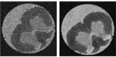
theoretical value of the SNR gain for the considered prototype is 2.5. In experiments performed on the test solution, the SNR gain is 2.2 as obtained with numerical simulations. Fig. 2 demonstrates that the ceramic probe performs better than the optimal solenoid when imaging the biological sample.
Discussion - The SAM estimation of the SNR factor was validated with an error inferior to 8%. The SNR gain estimation, that considers the inaccuracy of both models for the DR and the solenoid, was validated in one case. The SAM gives
a correct but overestimated value of the real SNR gain.
Conclusion - In this work we addressed the possibility to model and predict the performance of a dielectric probe for MRM based on the resonator first TE mode. The developed model has been confronted to numerical simulations and experiments and validated. Future works include the extension of this model to clinical dimensions and frequencies, and the development of a similar model for the first HEM mode (higher resonant mode) of the same type of resonator, with potential for clinical imaging [13]. In this context, preliminary experiments have been performed at 22.3 T (950 MHz NMR spectrometer Bruker Avance III HD). Early results show similar sensitivities of the HEM mode of the ceramic probe and the reference birdcage coil.
References [1] Ciobanu, Luisa. Pan Stanford, 2017.
[2] Park et al. Journal of Magnetic Resonance, 2009. [3] Webb, Concepts in magnetic resonance part A, 2011. [4] Kajfez, Guillon. Noble Publishing, Atlanta, GA 1998. [5] Neuberger et al. Concepts in Magnetic Resonance Part B, 2008.
[6] Haines et al. Journal of Magnetic Resonance, 2009. [7] Moussu et al., to be submitted.
[8] Nenasheva et al. Journal of European Ceramics Society, 2014. [9] Moussu, Ciobanu, et al., Advanced Materials, 2019. [10] Zhang et al. Electromagnetic theory for microwaves and optoelectronics. Springer, 2008.
[11] Sheen, Measurement Science and Technology, 2008. [12] Minard et al. Concepts in Magnetic Resonance, 2001. [13] Aussenhofer, Webb. Magnetic Resonance in Medicine, 2012.
Fig. 1 SNR gain for the test sample as a function of the ceramic permittivity and for several loss tangent values.
Fig. 2 – Ex vivo rat spinal cord image. Resolution: (25m)3. Left: solenoid.