Active Helicopter Rotor Control Using
Blade-Mounted Actuators
by
James Christopher Garcia
B.S.M.E. Virginia Polytechnic Institute and State University (1991) Submitted to the Department of Mechanical Engineering
in partial fulfillment of the requirements for the degree of
Master of Science
at the
Massachusetts Institute of Technology
February 1994
©
Massachusetts Institute of Technology 1994. All rights reserved.Author
Yepartment of Meianical Engineering December 8, 1993
Certified by
Professor Steven R. Hall Department of Aeronautics and Astronautics
Thesis Supervisor
Accepted by
r . ...
i
Professor Ain A. Sonin " ASSACHL[IU INSTIT6gai rman, Departmental Graduate CommitteeActive Helicopter Rotor Control
Using Blade-Mounted Actuators
by
James Christopher Garcia
Submitted to the Department of Mechanical Engineering on December 8, 1993, in partial fulfillment of the
requirements for the degree of Master of Science
Abstract
An aeroelastic model of a smart rotor system (which incorporates blade-mounted trailing-edge flap actuators and conventional root pitch actuation) is presented in linear time invariant state space form. The servo-flap deflections are modeled as producing incremental lift and moment variations, so that any linear aerodynamic actuator can be evaluated. This smart rotor model is used to conduct parametric studies involving rotor blade torsional stiffness, center-of-gravity offset, additional actuator mass, and actuator placement. Results on the effects of collective root pitch and servo-flap actuation on rotor thrust response are presented. Active rotor vibration reduction is demonstrated by applying higher harmonic control algorithms to the state space rotor model. Using reasonable servo-flap deflections, a rotor equipped with trailing-edge flaps can provide enough authority to cancel higher harmonic vibration.
Thesis Supervisor: Steven R. Hall, Sc.D.
Acknowledgements
I would like to thank my advisor, Professor Steven Hall, for his guidance and sup-port. I also wish to thank Mr. Frank Tarzanin and Ms. Joyce Peranteau of Boeing Helicopters for supporting the C60 rotor analysis program used in this research. In addition, I want to thank my office mates, Matthew Fox, Paul van Deventer, Eric Prechtl, and Kyle Yang for their friendship, advice, and endless coffee breaks. Lastly, I'd like to thank my parents for their love and support.
This material is based on work supported by a National Science Foundation Graduate Research Fellowship. Additional financial support was provided by Boeing Helicopters under Contract Nos. ABQ024, ACP853, and ADM651.
Contents
1 Introduction
1.1 Conventional Helicopter Rotor Control 1.2 Alternative Rotor Control Methods . .
1.2.1 Circulation Control ... 1.2.2 Mechanical Servo-Flaps . 1.2.3 Piezoelectric Actuation ... 1.3 Thesis Objective and Overview ....
2 State Space Rotor Model
2.1 Rotor Coordinates ... 2.2 Multi-Blade Coordinates ... 2.3 In Vacuo Blade Dynamics ...
2.3.1 Torsional Modal Analysis . . 2.3.2 In Vacuo Equations of Motion 2.4 Aerodynamic Model ...
2.5 Inflow Dynamics. 2.6 Hub Reactions ... 2.7 State Space Model ...
3 State Space Model Results
3.1 Model validation using C60 . . 3.2 Parametric Studies ...
3.2.1 Torsional Stiffness Study
19 19 23 23 25 27 30 33 . . . .33 . . . .35 . . . .. . . . .. .. . . . . .41 . . . .41 ... . .. 44
... ..49
. . . .55 ... . .. 56 . . . 59 65 67 70 71...
...
...
...
...
...
...
...
3.2.2 C.G. Offset and Additional Mass Study ... 74
3.2.3 Actuator Placement Study ... . 79
3.2.4 Aileron Reversal Study ... 81
4 Servo-Flap Actuation for Higher Harmonic Control 89 4.1 Higher Harmonic Control Loads ... .. 90
4.2 HHC Algorithms ... 92
4.3 Implementing HHC . . . ... 94
4.4 Multivariable HHC ... 100
5 Conclusions 107 5.1 Summary of Parametric Studies ... .. 107
5.2 Feasibility of Servo-flap Actuation for HHC ... 108
5.3 Further Research ... 109
A Rotor Blade Integrals 111 A.1 Aerodynamic Integrals . . . ... 111
A.2 Structural Integrals ... 112
B Matrices for Rotor Dynamics 113 B.1 Structural Dynamics, A and Matrices ... 113
B.2 Aerodynamics, A Matrices ... . 115
B.3 Hub Reactions, r and · Matrices ... . 116
B.4 Coupled Dynamics Matrices ... 118
C Inflow Dynamics 119
D Listing of Matlab Code 123
List of Figures
2-1 Block diagram of coupled rotor and inflow dynamics. Adapted from
Pitt and Peters [35]. ... 34
2-2 Helicopter rotor coordinates ... 35 2-3 Sectional rotor blade coordinates ... 36 2-4 MBC transformation from rigid flapping angle to rotor disk modes. . 38 2-5 Lumped torsional approximation of rotor blade. ... 43 2-6 Velocity components of differential chordwise element of mass: (a)
sectional view and (b) top view ... 46 2-7 Non-dimensional velocity components: (a) sectional view, (b) top view. 51
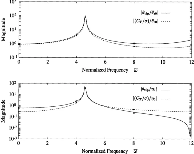
3-1 Continuous frequency response from state space model and C60 vali-dation points at U = 0, 4, and 8. Rigid flapping only case. ... 67 3-2 Continuous frequency response from state space model and C60
vali-dation points at Zi = 0, 4, and 8. Elastic torsion only case ... 68 3-3 Continuous frequency response from state space model and C60
vali-dation points at 0 = 0, 4, and 8. Rigid flapping and elastic torsion coupled by c.g. offset ... 69 3-4 The effect of blade torsional stiffness on Ge,o (jWU) for H-34 rotor in hover. 72 3-5 The effect of blade torsional stiffness on Go0(jU) for H-34 rotor in hover. 73 3-6 The effect of blade torsional stiffness on thrust Ge,,(ju) for H-34 rotor
in edgewise flight ( = .25) ... 74 3-7 The effect of blade torsional stiffness on Go(jz) for H-34 rotor in
3-8 The effect of c.g. offset on Ge,0(ju) for H-34 rotor in hover. Note that cg = 0.2 case is unstable. ... 76 3-9 The effect of c.g. offset on G,0(ju) for H-34 rotor in hover. Note that
xcg = 0.2 case is unstable. ... 77 3-10 The effect of c.g. offset on G,(j) of H-34 rotor in edgewise flight
(A = 0.25). Note that ,cg = 0.2 case is unstable ... 78 3-11 The effect of c.g. offset G,,o(j) for H-34 rotor in edgewise flight ( =
0.25). Note that xcg = 0.2 case is unstable ... 79 3-12 The effect of additional actuator mass on G,0(jU) for H-34 rotor. . . 80 3-13 The effect of additional actuator mass on G,7o(jw) for H-34 rotor in
hover ... 81 3-14 The effect of actuator placement on G,7o(jU) for H-34 rotor in hover.. 82 3-15 The effect of actuator placement on G,0(jw) for H-34 rotor in edgewise
flight ( = 0.25). ... 83 3-16 Aileron reversal study for the H-34 rotor in hover. Based on state space
model analysis. ... 84 3-17 Aileron reversal curves for typical rotor parameters and the H-34 rotor
in hover. Based on simplified analysis. ... 87
4-1 HHC loop and sensitivity transfer functions: root pitch actuation. .. 96 4-2 HHC loop and sensitivity transfer functions: servo-flap actuation. . 97 4-3 Nichols plot of HHC loop transfer function: root pitch actuation.... 98 4-4 Nichols plot of HHC loop transfer function: servo-flap actuation.... 99 4-5 Open- and closed-loop poles for various Go (s) HHC systems: o =
open-loop pole, * = closed-open-loop pole ... 100 4-6 Open- and closed-loop poles for various G0o (l) HHC systems: o =
open-loop pole, * = closed-open-loop pole. ... .. 101 4-7 Block diagram of LQR/FSCF closed loop system . ... 104 4-8 Singular value plot of sensitivity transfer function matrix. LQR/FSCF
List of Tables
2.1 State space equation for rotor system dynamics ... 62
2.2 State space equation for the hub loads. ... 63
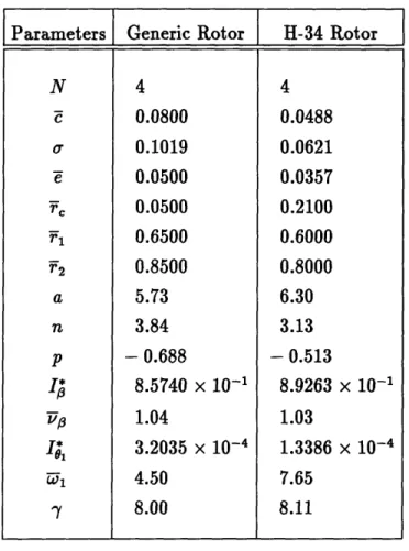
3.1 Baseline parameters of generic and H-34 rotors. ... 66
3.2 Typical rotor parameters. ... 86
4.1 Thrust response data for H-34 rotor at 4. ... 91
Notation
An attempt was made to use notation as consistent as possible with that of Johnson [19] and of Fox [12]. Dimensionless quantities are normalized by the rotor radius R, the rotation rate 1, and/or the air density p, where possible.
a blade section lift-curve slope cla A rotor area, rR2
A state matrix
A" rotor integral, see Appendix A
B state control matrix
B" rotor integral, see Appendix A c blade chord
c normalized blade chord, c/R
C output matrix
CL roll moment coefficient, M,/pAR(OR) 2 CM pitch moment coefficient, MY/pAR(fIR) 2
CT thrust coefficient, T/pA(AR) 2 CT/a blade loading
C" rotor integral, see Appendix A
D output control matrix
D" rotor integral, see Appendix A e flap hinge offset
E" rotor integral, see Appendix A
F optimal feedback gain matrix F, section radial aerodynamic force
F, section aerodynamic force parallel to disk plane FZ section aerodynamic force normal to disk plane F" rotor integral, see Appendix A
G(s) plant transfer function GJ torsional stiffness
G rotor integral, see Appendix A
H(s) compensator transfer function
Hk rotor integral, see Appendix A
I identity matrix
I3 blade moment of inertia about the flapping hinge, JfR m2(r)dr
I,3 normalized flapping inertia, I/Ib 1s sectional pitch inertia of blade Is, pitch inertia of k th torsion mode
I*, normalized pitch inertia of k th torsion mode, I,/Ib J* optimal cost
J" rotor integral, see Appendix A K,3 flapping hinge spring constant
Kek generalized stiffness of k th torsion mode K" rotor integral, see Appendix A
K stiffness matrix for lumped torsional system L Lagrangian
L" rotor integral, see Appendix A m blade sectional mass
MF flapping moment of blade, positive upward
MF
normalized
flapping moment,
MF/IbQf2MZ rotor hub roll moment, positive toward retreating blade My rotor hub pitch moment, positive rearward
Mhn rotor integral, see Appendix A
M mass matrix for lumped torsional system n lift coefficient of servoflap cl,
W normalized lift coefficient of servoflap, cl,,/a N number of blades
N blade torsion
N normalized blade torsion N/IbQ2
Naero blade torsion due to aerodynamics
Nk blade torsion of the k th mode p moment coefficient of servoflap, c,,
p- normalized moment coefficient of servoflap, cm,,/a
q blade index
Q state weighting matrix r rotor disk radial coordinate
rF normalized radial coordinate, r/R rl inboard servoflap location
r2 outboard servoflap location
r, root cutout
R rotor radius
R control weighting matrix s Laplace variable
s normalized Laplace variable, i/n
S(s) sensitivity transfer function
t time
t nondimensional time, = Qt
T rotor thrust, positive upward T* kinetic coenergy of the rotor blade
u control input vector
zup velocity ratio of blade section, normal to disk plane UR velocity ratio of blade section, in radial direction
UT velocity ratio of blade section, parallel to disk plane
U section resultant velocity ratio, U/UT + u
V potential energy of the rotor blade x rotating blade chordwise coordinate x non-rotating coordinate positive aft
x normalized chordwise coordinate, x/c
Xcg center of gravity offset, positive aft of quarter chord
z state vector
non-rotating coordinate positive to the right y output vector
z blade coordinate, positive upward i rotor coordinate, positive upward a blade section angle of attack
°ad rotor disk angle with respect to helicopter velocity ,f flapping angle, positive upward
-y Lock number, pacR4/Ib
r aerodynamic hub reaction matrices, see Appendix B
A dynamic matrices, see Appendix B 7 servoflap angle
Or blade root pitch angle
Ok modal coordinate for the k th torsion mode A rotor inflow ratio, Af + Ai
Ac vertical climb inflow ratio
Af free stream inflow ratio, (V sin ad + v)/flR Ai induced inflow ratio, v/fR
A aerodynamic matrices, see Appendix B A rotor advance ratio, V cos ad/IIR
yV blade flapping frequency
v-1 normalized blade flapping frequency, vO/l
~p(r) blade flapping fundamental mode shape, ( - e)
~0k (r) k th torsional mode shape
(,6^ k k th torsional mode shape vector p air density
Cf rotor solidity Nc/7rR
~b
section
inflow
angle, tan-'(up/uT)
I inertial hub reaction matrices, see Appendix B
0p
azimuth angle of rotor blade 9bq azimuth angle of q th rotor blade'I' root pitch actuation matrices, see Appendix B wp free-flapping frequency, KO/i 3
0w- normalized free-flapping frequency, wl3/ w frequency [rad/s]
ZZT nondimensional frequency w/1I
Wk natural frequency of k th torsion mode
-k normalized natural frequency of k th torsion mode, wk/02 Qn rotor speed [rad/s]
Subscripts
0 collective
c longitudinal cyclic
f free stream
i induced flow
blade root lateral cyclic
Superscripts
* nT
normalized by Ibderivative with respect to r exponent on r, see Appendix A transpose
r
Chapter 1
Introduction
Conventional helicopter rotors are controlled through a swashplate, a mechanism which transmits commands from the fixed frame to blade root pitch angles in the rotating frame. An alternative method to helicopter rotor control involves the use of blade-mounted trailing edge flaps to twist the rotor blades. One possible method to actuate trailing edge flaps is the use of piezoelectric materials [43].
Before proceeding with full-scale testing, an analytical tool to evaluate servo-flap performance for various rotor control applications would be useful. This thesis
will present the refinement of a helicopter rotor model equipped with blade-mounted aerodynamic actuators, as well as conventional root pitch actuation. Specifically, a linear time invariant (LTI) state space model is developed, which allows the servo-flap rotor system to be evaluated using classical and multivariable control techniques.
Using the state space model, parametric studies are performed and control techniques for vibration suppression are investigated.
1.1 Conventional Helicopter Rotor Control
In a conventional helicopter, rotor control is achieved through full-blade feathering. Various root pitch actuators which operate in the rotating or fixed frame have been developed. Traditionally, full-blade feathering is accomplished with a swashplate
con-the vertical movement of con-the swashplate. Collective swashplate commands simulta-neously increases the pitch of all the blades to provide thrust control. Tilting the swashplate generates cyclic commands which vary the blade pitch angle sinusoidally with a period of one rotor revolution. This effectively tilts the rotor disk in the de-sired direction, providing maneuvering control. To a lesser extent, electro-hydraulic actuators in the rotating frame have been used to provide root pitch control. The development of such an actuator is described in Reference 21.
Much research effort has been directed at the use of swashplate actuation for higher harmonic control (HHC), in which most of the control effort is centered at the NQ frequency, where N is the number of blades and S is the angular velocity of the rotor. A survey by Hooper of wind tunnel and flight test data concluded that blade-vortex interaction (BVI) is the primary source of NQ rotor vibration [18]. Work on HHC conducted by Boeing, Hughes, Sikorsky, NASA, and many other organizations has led to successful wind tunnel and full scale flight testing [49], [30], [39], [40]. In general, electrohydraulic actuators drive the swashplate at NSQ on top of the standard collective and cyclic controls commanded by the pilot. The NSf swashplate commands in the fixed frame are modulated to (N - 1),Q, Ni, and (N + 1)SQ pitch variations in the rotating frame. There are a number HHC algorithms used to provide closed loop vibration control. Some of these techniques will be discussed further in Chapter 4. For now, a brief overview of HHC research based on root pitch actuation is presented.
Reference 49 describes the development of an HHC system for a 4-bladed OH-6A helicopter and subsequent flight testing. This work was conducted by Hughes under contract with NASA and the U.S. Army. Flight tests were conducted with open- and closed-loop HHC at speeds up to 100 knots. Three hydraulic actuators provide 4SQ swashplate commands on top of the standard collective and cyclic commands. These devices were capable of producing harmonic root pitch amplitudes of 1 deg at up to 90 Hz. All three actuators could provide 2 deg of collective authority. Accelerometers mounted beneath the pilot seat measured vertical, lateral, and longitudinal forces. Open-loop or manual testing involved varying the phasing of the 4S) commands to reduce RMS levels of vibration. An adaptive controller based on a Kalman filtering
scheme to estimate plant parameters was used to close the loop. Both open- and closed-loop testing demonstrated significant reduction in vibration levels, with the open-loop testing showing better overall reduction. Vibration attenuation varied with forward speed. In all flight cases, increases in blade bending and pitch link loads were
noted.
Sikorsksy implemented HHC on a 4-bladed S-76 helicopter to determine the extent of open-loop vibration reduction [30]. Flight tests at speeds up to 150 knots were conducted including climb/descent and turn maneuvers. Electro-hydraulic driver actuators were placed at the input sides of the main rotor swashplate servos. These actuators provided 41 deg pitch amplitudes at up to 20 Hz. Flight tests showed good vibration reduction which was nearly constant with airspeed. A theoretical analysis predicted an optimum pitch amplitude of 2 deg for vibration reduction at 150 knots, but the available actuators were limited by the hydraulic fluid flow capacity. These tests also noted a load increase on the pitch links used for main rotor control.
An extensive program of HHC analysis, design, and testing was conducted by Boeing Helicopters over several years. Reference 39 traces the development of a 4-bladed HHC model rotor from analytical study to wind tunnel testing in the late
70's. 90% suppression of 42f vertical force, pitching moment, and rolling moment was demonstrated on a scaled, 4-bladed, 3.05 m diameter hingeless rotor. The swashplate was controlled by extremely accurate electro-hydraulic servos that could provide 1.5
deg pitch commands at 90 Hz. This HHC system also incurred an increase in control loads, blade fatigue loads, and required power. Specifically, a maximum 65% increase in pitch link loads was noted at an advance ratio of 0.3, and overall power requirements increased 1.7%.
Wind tunnel HHC testing of a dynamically scaled 3-bladed CH-47D Chinook ro-tor was conducted by Boeing Helicopters in 1985 [40]. This roro-tor was flown through
a wide test envelope at speeds up to 188 knots. Specially designed hydraulic actua-tors featuring long seal life could provide 3 deg of pitch variations at 69 Hz, which
to the swashplate as opposed to the typical three actuator configuration. Using a strain gage balance to measure rotating hub loads, various HHC control laws were evaluated. These included adaptive, scheduled gain, and fixed gain algorithms with the fixed gain controller providing the best vibration reduction. A control loop re-sponse bandwidth of 1 Hz was deemed sufficient for maintaining HHC performance during maneuvers and gusts. The resulting HHC system was able to continuously and simultaneously suppress three vibratory components over a wide range of changing operating conditions. The fixed gain system provided a 90% reduction in 32 vertical force and 2 and 4Q inplane shears throughout the test envelope.
Individual blade control (IBC) is a concept in which blade-mounted actuators and sensors provide appropriate control in the rotating frame. The application of IBC towards gust alleviation, attitude stabilization, vibration reduction, lag damping augmentation, and stall flutter suppression is described by Ham [17]. An effective IBC system is defined by several subsystems, each of which controls a specific blade mode, i.e., first flapwise bending, first torsional, etc. Most IBC work to date utilizes root pitch as the control input. Wind tunnel tests incorporated electrohydraulic servos in the rotating frame and blade mounted accelerometers as sensors. For a 3-bladed rotor, IBC can be accomplished using swashplate actuation, since the swashplate has three degrees of freedom (collective, lateral tilt, and longitudinal tilt).
Using the root pitch actuation, significant progress has been made in helicopter rotor control, particularly in the area of vibration alleviation. However, the swash-plate mechanism is limited by its three degrees of freedom and by increased control loads and blade stresses associated with feathering the entire rotor blade. Placing root pitch actuators in the rotating frame provides more degrees of freedom, but increases the complexity of the rotor hub design. The additional electrohydraulic equipment increases the operating cost of the aircraft and imposes a weight penalty. A more elegant method of rotor control which uses a minimum of control effort is desired.
1.2 Alternative Rotor Control Methods
In addition to the swashplate, blade-mounted methods which provide aeroelastic actu-ation in the rotating frame have been developed. Motivactu-ation for these blade-mounted alternatives include performance enhancement [16], improved vibration control [27], and individual blade control (IBC) [17]. Blade-mounted actuation methods include circulation control [28], [20], and mechanical servo-flaps [7],[23]. More recently, piezo-electric materials have been used for aeroelastic control [22], [4], [43]. In addition, passive blade-mounted devices which include tuned flaps and free tips have also been investigated [5], [45].
1.2.1 Circulation Control
Circulation or jet flap control of airfoils is based on the Coanda effect, in which tangential air flow along a rounded airfoil delays boundary layer separation, providing a relatively high sectional lift. Jet flap rotors utilize fairly conventional airfoil shapes with trailing edge slots for air flow, which are sometimes used for propulsion. In general, circulation control rotors (CCR's) utilize elliptical airfoil blades equipped
with blowing slots on the trailing and/or leading edges. Air flow is supplied in the hub fixed frame and conducted to the rotating blades through some type of duct system. Research effort has been directed at using this actuation method for trim and vibration control of rotor systems for the past two decades.
The Giravions Dorand Jet-flap rotor was tested in the NASA-Ames 40x80 wind tunnel in the early 70's [28]. This 12 m diameter, two-bladed teetering rotor was equipped with jet flaps which provided rotor propulsion, as well as higher harmonic control. A conventional swashplate provided collective and monocyclic root pitch commands. HHC jet flap control at 2, 31, and 4 was controlled by a cam mounted in the fixed hub frame. This rotor demonstrated a simultaneous 50% reduction in blade bending and vertical hub loads for advance ratios in the range t = 0.4-0.6.
of this study was to eliminate root shear forces while monitoring blade bending loads and power. Conventional root pitch was used for trim control with the jet flaps providing 2-11l control. It was found that the elimination of root shear loads was
due to the elastic twisting caused by the jet-flaps.
A notable CCR project which led to actual flight testing is the XH-2 flight demon-strator program. Reference 20 traces the development and evolution of this CCR pro-gram. Initial analytical work predicted substantial vibration reduction using higher harmonic inputs. The XH-2/CCR was first tested on the whirl stand and in the wind tunnel. Airflow to the rotating blades was regulated using a flex ring valve (FRV) system. Inlets to the blades pointed downward facing a flexible swashplate-like ring. By pushing this ring up against the inlets, airflow is restricted. Collective control is achieved by moving the ring vertically, cyclic control by tilting the ring, and higher harmonic control by warping the ring. Collective control was augmented by a con-ventional swashplate. Flight testing of the XH-2 indicated the heavy lift capability of CCR's. Defined benefits included a reduction of profile drag due to boundary layer control, a corresponding 20-25% reduction in required rotor torque, higher efficiency at higher blade loadings compared to conventional rotors, and a pneumatic control system with smaller control loads.
The X-wing is a V/STOL concept in which the aircraft operates as a conventional rotor at hover and low flight speeds and converts to a fixed wing craft at higher speeds. Four X-wing programs were conducted at the David Taylor Naval Ship Research and Development Center (DTNSRDC) [1], the Lockheed California Company (LCC) [2], Boeing Vertol [37], and Sikorsky [47]. All of these rotors incorporated an elliptical airfoil shape with chord thickness tapered toward the tip. Air flow was provided to the blades by an azimuthally spaced valve system at the hub. The DTNSRDC X-wing project was dubbed the RBCCR (Reverse BloX-wing Circulation Control Rotor). The RBCCR was a 6.7 ft diameter rotor with very rigid blades and a valve-type control system consisting of eight azimuthally spaced valves. A number of wind tunnel test were conducted from 1975 to 1979 to prove the aerodynamic feasibility of the circulation control concept. A 25 ft diameter X-wing was developed by Lockheed as a
demonstrator model and was tested in the NASA-Ames 40x80 ft wind tunnel and the LCC whirl tower. This model demonstrated conversion from rotating to fixed wing flight at flight speeds up to 180 knots. The Boeing 10 ft. X-wing model incorporated 16 trailing edge valves and 9 leading edge valves to maintain lift on the retreating side of the rotor. Circulation control could be provided from the first through fifth harmonics. In addition, the Boeing X-wing featured mechanical collective pitch control from 8 to -12 deg. The Boeing CCR also demonstrated HHC control techniques to reduce flapwise bending loads. The X-wing model tested at the Sikorsky/United Technologies Research Center was a 1/6 scale, 10 ft diameter 4-bladed rotor which was equipped with two rings of 24 azimuthally spaced valves. The upper ring supplied trailing edge blowing while the lower one fed leading edge slots. Using man-in-the-loop HHC, 70-95% vibration reductions were achieved.
1.2.2
Mechanical Servo-Flaps
The use of blade-mounted servo-flaps for rotor control was demonstrated as early as 1950 [7]. This "aerodynamic servo-controlled helicopter rotor system" featured an outboard flap mounted on a spar at the 75% radial station. The flap was essentially an external airfoil whose lift, acting at moment arm about the pitch axis, provided a torsional moment to twist the rotor blade. The servo-flap was actuated through a mechanical linkage system of bell cranks and push-pull rods and could be deflected up to 15 deg. Using only flap actuation, the rotor system could produce up to 1500 lbs of thrust and ±7 deg of rotor tilt, more than sufficient for trim and maneuvering control. One drawback to the system was a 6.5% increase in required power attributed to profile drag of the flap servomechanism. An analytical model of this rotor system was presented by Payne in 1959 [33].
While not strictly a servo-flap system, a rotor system with an independently mov-able inboard blade panel was presented in Reference 11. The motivation for this system was to improve propulsive capability at higher advance ratios which was ac-complished by prescribing a non-harmonic pitch schedule for the inboard panel. This
and maintain an advance ratio as high as 0.60. A recommendation for further work on this system included the use of a large chord trailing edge flap to obtain similar results.
The use of blade-mounted trailing edge servo-flaps has been continuously devel-oped by Kaman Corporation, and has been implemented in current helicopters, in-cluding the SH-2 Seasprite and the K-1200 Synchropter. The Seasprite utilizes tor-sionally rigid blades with soft torsional springs at the root so that the entire blade "follows" the servo-flap command. The K-1200 has dual two-blade intermeshing ro-tors with a teetering root configuration. The K-1200 servo-flaps utilize elastic blade twist for rotor control. In these designs, servo-flap deflections are commanded by a swashplate. Both of these rotors exhibit significantly lower control loads compared to conventional root pitch actuation.
As with the system presented in Reference 7, the Kaman CTR (Controllable Twist Rotor) actuates the rotor by providing an aerodynamic moment to twist the blade producing a favorable spanwise pitch angle distribution. References 3 and 48 discuss the importance of blade pitch angle distribution to rotor operation. It was concluded in Reference 48 that a high negative twist provides lower power requirements at low flight speeds while a lower negative twist can minimize vibratory loads at higher
speeds. Reference 3 concluded that a "torsionally flexible blade with dual control inputs at the blade root and blade tip can provide significant improvements over existing rotor systems." This work and others provided motivation for the CTR.
A number of reports document the development of the Kaman CTR from analysis to experimental wind tunnel testing [23], [24], [26], [29]. The baseline CTR was based on the 4-bladed H-34 rotor system. The flaps were actuated through a system of rods and cranks controlled by a secondary swashplate. This swashplate was in addition to the primary one for root pitch control. Reference 38 outlines the development of the CTR from preliminary analytical work to pre-wind tunnel testing design work and provides a thorough description of the CTR hardware design and rotor parameters.
Reference 24 presents a broad parametric evaluation of the CTR system to find an optimum configuration. The variable parameters were built-in twist, torsional
stiff-ness, faired vs. external flap, flap size, and flap placement. These design parameters were chosen to minimize rotor power, blade bending loads, and maximum local angle of attack. Based on this analytical work, the benefits of the CTR included a 30% decrease in rotor solidity compared to a conventional rotor producing 1 g of thrust, a 15% reduction in required power, and a 30% decrease in blade bending loads.
In addition, the use of higher harmonic or multi-cyclic control on the CTR led to development of the multi-cyclic controllable twist rotor (MCTR). The analysis pre-sented in [26] predicted the virtual elimination of vibratory loads, as well as a 50% reduction in blade bending moments using a combination of 1 through 4 control inputs. Reference 46 outlines the development of a feedback control system for the MCTR. Results from MCTR testing in the 40x80 ft NASA-Ames wind tunnel are presented in [29]. A significant reduction in blade bending moments and blade-root
actuator control loads was achieved. For the MCTR, special electro-hydraulic actua-tors were placed in the rotating frame to provide higher harmonic servo-flap control. These actuators could provide flap deflections of up to 6 deg at 2, 3, and 4.
An additional feature of the CTR system was automatic blade tracking. This was accomplished with small electric motors in the rotating frame which would provide the appropriate offset to the individual servo-flap control rods.
1.2.3 Piezoelectric Actuation
Recently, the use of so called smart materials for aeroelastic control has been the focus of research. Feasibility studies for smart material actuation have been presented in a number of previous works [32], [44], [41]. Specifically, the use of piezoceramic materials has received much attention, due their high strain and high bandwidth capabilities. Direct structural control using piezoelectric materials has been proposed by Lazarus and Crawley [8], [22], Barrett [4], and Nitzsche [31]. Research done by Spangler and Hall [43] investigated piezoelectric actuation of trailing edge servo-flaps. Lazarus and Crawley demonstrated the use of piezoceramic material to induce strain in isotropic and anisotropic plates [8]. Using composite plates with
bend-trol of a plate-like lifting surface in the wind tunnel [22]. While applicable to smaller lifting surfaces such as missile fins, this type of actuation scheme may not have enough authority for rotor blade control. A drawback is the structural bending and twist cou-pling that is required. This may not be feasible for a typical rotor blade which has a high aspect ratio compared to fixed wings.
In the area of helicopter rotor control, Barrett developed the concept of direc-tionally attached piezos (DAP's) in an attempt to uncouple torsional and bending actuation [4]. Using partial attachment and shear lag effects, a piezoelectric actu-ator with essentially isotropic properties could be incorporated into the rotor blade structure. Barrett applied DAP's to a 1/8 scale rotor model from the ITR program and managed to produce ±2 deg of pitch deflection at resonance. At DC, the pitch response was only ±0.1 deg. Using the DAP system, active flapping vibration control using tip accelerometer feedback provided a 96% reduction in tip deflection ampli-tudes.
One proposed method of rotor blade structural control utilizes embedded piezo-electric polymer film sensors and piezoceramic actuators [31]. These devices would be specially shaped to sense and actuate specific blade modes. A perfectly collocated sensing/actuation scheme is highly desirable from a control systems standpoint. Part of the motivation for this concept is the development of a simple IBC modal con-trol system as described by Ham [17]. A drawback to this approach, as is the case with many smart material methods, is the limitation of available material properties. Most materials cannot produce enough strain or have limited bandwidth to implement certain smart structure concepts. Shape memory alloys have high force capability, but have very low bandwidth, making them useful for only quasi-static applications. Piezoceramics are high bandwidth actuators, but cannot exert enough strain for high authority structural control of specific blade modes.
A novel approach to incorporate these smart materials into rotor control is the use of piezoceramic actuators to drive an aerodynamic surface, i.e., a trailing edge flap. Instead of high authority control of the rotor blade structure, these piezo servo-flaps would redirect aerodynamic energy to twist the rotor. One approach is a piezo-bender
configuration developed by Spangler and Hall [41], [42], which is also the subject of ongoing research at MIT. Piezoceramics are essentially large force, small displacement actuators. The trick is to amplify the small displacements to relatively larger ones needed for servo-flap deflection.
Spangler and Hall [43] used a cantilever bender element which translates the ben-der's tip deflection to servo-flap deflection through a hinge mechanism. This device utilized impedance matching arguments to define an optimal flap hinge geometry. This optimal geometry insures that the strain energy created by the piezoceramic ben-der is efficiently transmitted to flap hinge moment. In the wind tunnel, peak-to-peak flap amplitudes of 14.5 deg at 4 Hz and an air speed of 11.2 m/s were demonstrated [41]. Extrapolating to full scale, a peak-to-peak amplitude of 10.4 deg at 11.25 Hz and an air speed of 148 m/s is achievable. This corresponds to a servo-flap at the 70% span of a Boeing Chinook rotor in hover, providing 31 actuation. This actua-tion method has been proven in typical secactua-tion testing and is currently being refined. By using a flexure assembly instead of mechanical hinges and constructing a more efficient piezoelectric bender element, performance improvements over the original design are anticipated. Benefits of piezoelectric servo-flap include high bandwidth capability and a relatively simple design. Instead of a mechanical linkage system from the fixed to rotating frame, these solid state devices can be controlled by simple electrical sliprings. Their modular design also allows for a spanwise segmented flap configuration.
Servo-flap actuation is chosen as the focus of this thesis because of its extensive de-velopment and implementation in current helicopter designs. Before proceeding with rotating frame testing, an analytical tool to evaluate the performance of a servo-flap rotor system is desirable. A fundamental issue is the amount of servo-flap deflec-tion and associated control loads required for various rotor applicadeflec-tions. Servo-flap actuator dynamics are neglected so that any actuation method, not specifically piezo-electric, can be evaluated separately.
1.3 Thesis Objective and Overview
Due to the complexity of the helicopter rotor's operating environment, even in ideal conditions, a comprehensive aeroelastic computer simulation is required to predict the rotor's behavior with some degree of accuracy. In general, rotor analysis routines are based on a time marching, iterative solution technique, and incorporate, to some degree, non-linear aerodynamic and structural effects. These tools are an important developmental step before proceeding with actual hardware construction but are ill-suited for certain tasks. A simpler and faster analysis would be useful for parametric studies and as a preliminary design tool. The objective of this thesis is to present a refined state space model of a helicopter rotor which incorporates blade-mounted flaps and root pitch control. This model will be used to demonstrate the effectiveness of these two actuation methods for various smart rotor applications.
Chapter 2 outlines the derivation of the LTI state space rotor model. Important simplifying assumptions include time invariant dynamics and linear aerodynamics. The LTI approximation is accomplished by using multi-blade coordinates (MBC) to transform dynamics from the rotating to the fixed frame. This work is an extension of initial research done at M.I.T. by Fox [12]. Portions of the model derivation chapter are taken from [12, Chapter 4]. New additions to this rotor model include span-varying rotor blade parameters, a chordwise center-of-gravity offset which couples rigid flapping and elastic pitch, a 83 hinge which couples rigid flapping and rigid pitch, an arbitrary number of torsional modes, and separate aerodynamic and structural rotor integrals.
Chapter 3 presents validation results and a number of parametric studies using the state space rotor model. The aeroelastic rotor program C60 developed by Boeing Helicopters is used to validate the state space model at discrete frequency points, Oi, NI, and 2Ni. Using continuous frequency responses, the effect of parameter variations on the open loop helicopter rotor plant is investigated. Of primary interest is the thrust response due to collective root pitch and servo-flap control inputs. Im-portant parameters are the rotor blade's torsional stiffness and servo-flap placement.
In addition, the effect of center-of-gravity offset from the pitch axis and additional mass due to the actuator is investigated.
In Chapter 4, higher harmonic control (HHC) techniques are applied to the open loop helicopter plant derived in Chapter 2. Based on previous work on HHC al-gorithms [15], a continuous time compensator will be applied to individual transfer functions to compare the closed loop performance of root pitch and servo-flap ac-tuation. A frequency weighted linear quadratic regulator (LQR) approach will be applied to the state space rotor model to demonstrate multivariable vibration reduc-tion. In addition, the required control effort of root pitch and servo-flap actuators for HHC will be compared. Finally, a summary of the important conclusions and some suggestions for further development of the state space rotor model will be presented in Chapter 5.
Chapter 2
State Space Rotor Model
In this chapter, a state space model of an actively controlled helicopter rotor is de-rived. A semi-articulated rotor model with rigid blade flapping and elastic torsion is assumed. The inputs to this system are root pitch angle and servo-flap deflection. The outputs of interest are the hub loads: vertical force, pitching moment, and rolling moment. The model is derived by first finding the equations of motion governing the structural blade dynamics in vacuo or in the absence of aerodynamic effects. The aerodynamic loads which force the system are then derived. The dynamics and forc-ing terms will be derived in the rotatforc-ing frame and then transformed to the fixed frame using multi-blade coordinates. In addition, a dynamic inflow model developed by Pitt and Peters [35] will be presented. Finally, the three major elements of the model (structural dynamics, aerodynamic loads, and dynamic inflow) are coupled to-gether as shown in Figure 2-1. Before proceeding with the derivation, the notation and coordinates used in describing the helicopter rotor system will be explained.
2.1 Rotor Coordinates
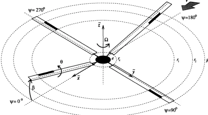
The coordinates of the rotor disk may be described by the polar coordinates r, the radial position, and i/, the azimuthal angle. In general, American helicopter rotors
Blade Motions
Controls 3
Inflow
Loads
Figure 2-1: Block diagram of coupled rotor and inflow dynamics. Adapted
from Pitt and Peters [35].
Figure 2-2. Often, the right and left halves of the rotor disk are referred to as the advancing and retreating sides, respectively. The servo-flap spans the rotor blades from rl to r2 and deflects an angle 77 defined positive downward. For this model,
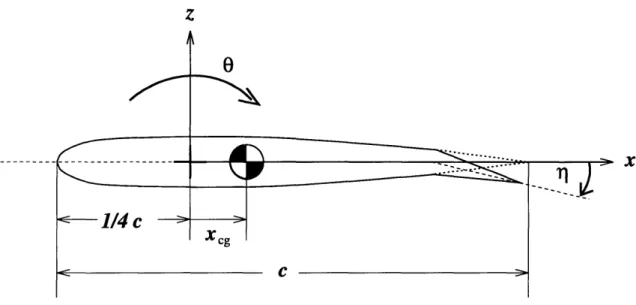
each rotor blade is allowed to pitch rigidly and elastically with an angle 6, defined positive nose up, and rotate rigidly about a flapping hinge at r = e with an angle P, defined positive up. The rotor blade airfoil spans from r = r to R. The sectional coordinate frame of the rotating blade is illustrated in Figure 2-3. For this model, the pitch axis coincides with the elastic axis and aerodynamic center at the quarter
chord. The center-of-gravity or c.g. offset is denoted by xz,, defined positive aft of the quarter chord. A nonrotating cartesian coordinate frame is attached at the hub
center with pointing aft ( = 0 deg), y to the right ( = 90 deg), and i pointing upward. The rotor hub loads are evaluated relative to this nonrotating frame. In addition, a coordinate frame rotates with the rotor blade with the x axis pointing toward the trailing edge, the r axis pointing toward the tip along the quarter chord,
BLADE DYNAMICS AERODYNAMIC MODEL INFLOW DYNAMICS c I
1
7
V ---- -- - - ---_~~~~ < , I ^: =180°v i~~~~~~~~~~~ I l Xr r dr I ~ ~ ~~~~~~~~~, , I~~~~~~~~~~ , I I . ."""/J ///It , /
,~J ,,
--- -...-.-... - - - -- _- - -- =90Figure 2-2: Helicopter rotor coordinates.
and the z axis pointing upward. The rotor blade's dynamics and sectional properties are evaluated using this rotating coordinate frame. For convenience, the normalized radial position is r = r/R, and the normalized chordwise position is z = x/c.
2.2 Multi-Blade Coordinates
In general, the dynamics of a rotor system are periodic, but the evaluation of contin-uous frequency response functions requires a linear time-invariant (LTI) assumption. Using multi-blade coordinates (MBC), an LTI approximation of the rotor dynamics will be derived. The mathematics involved in transforming the blade's degrees of freedom in the rotating frame to the rotor disk modes in the non-rotating frame are presented in this section. A more formal treatment of multi-blade coordinates is given in Johnson [19, Chapter 8].
Using the discrete Fourier series, one can fit a periodic function at several discrete
I I I I I I I I I I I I I I I I I IBI ~ J B _~~ _ ~ ~ -- /--.IV --- - - -- - - - -- -__ , T .... _ -- ___J Ir_ > A -1 -. l I I I
z
'
1/4 c
c
0 X.-'-6 C.< C 3-C - .. I
Figure 2-3: Sectional rotor blade coordinates.
Multi-blade coordinates use the N lowest Fourier coefficients to transform from rotor blade degrees of freedom in the rotating frame to rotor disk modes in the fixed frame. The total number of degrees of freedom are maintained, because there is a degree of freedom for each of the N blades. For example, the flap angles of the rotor blades
are i, /32, . .. fN. The blade angles are transformed by the discrete Fourier series to
the fixed frame coefficients o, fcls, s ... d, which represent flapping modes of the rotor disk. The fixed frame coefficients are
f
=
NS/(i/,q),
(2.1)
2 N
q=1
2 N
fins =
-
EfI(lq) sin(nq), (n
<N/2)
(2.3)
q=l1 N
ad = -(?kq)(-1) q X, (N even)
.
(2.4)q=1
The coefficients f, ,, n., and
fid
are the multi-blade coordinates, and q is the azimuthal position of the qth blade (1 < q < N). The differential term /d exists only when there are an even number of blades. For the purpose of this research, we willi
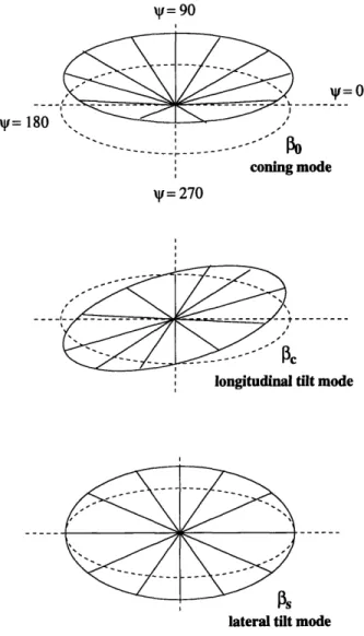
retain only the first three multiblade coordinates. The remaining differential terms represent reactionless modes which cause no net hub force or moment. Therefore, the MBC expansion of the flapping angle will be given by
P(2) = Po + c cos + sin . (2.5) It is also assumed that all of the rotor blades behave identically. Figure 2-4 illustrates the transformation from the rotating frame flapping angle, 3, to the rotor disk modes, fo,
flc,
and U.. The coning mode is represented by the collective coordinate fi0. The longitudinal and lateral tilt modes are represented by the cyclic coordinates /ic andP,,
respectively. Two methods for performing the MBC transformation include the substitution method and the summation operator method, which are discussed below. The substitution method will be used to transform differential equations in the rotating frame to MBC. In this work, the governing equations of motion in the rotating frame will have constant coefficients. The MBC expansion for the degree of freedom is substituted into the rotating frame equation. As an example, an equation of the formmi +
kx
= f (2.6)will represent the dynamics of x in the rotating frame. Taking derivatives with respect to non-dimensional time (,b = aft), the degree of freedom x is expanded as
x = X0 + xC cos ? + x sin , (2.7)
i = io + i,
cos
'
+ i. Sin -
sin ? + x, cos ,
,
(2.8)
i = o + XC cos ? + i, sin ik - 2i sin O + 2 cos - xC cos b - x sin . (2.9) Inserting these into Equation (2.6) and collecting coefficients of similar terms, the
V= 90
XV=O
'=1
coning mode
it = 270
longitudinal tilt mode
!
lateral tilt mode
resulting equations of motion in MBC matrix form are 0 m ' + 0 2m 2ci + 0 0 t
-2m
0 ', ,J
[k 0 0 x f [k-r
. = (2.10) O Ok-m
XfIn addition to the substitution method, summation operators will be used to transform generalized forces on the blades to forces on the rotor disk modes. The operators are N ()o = N '(') (2.11) q=1 2 N
() =
Z
(.) cos(bq),
(2.12)
q=1 q=lIn general, the rotating frame forces on the blades are periodic aerodynamic loads due to the azimuthally varying velocity field. As an example, the summation operators will be applied to a forcing term of the form
f = (1 + sin b)2x . (2.14)
Using trigonometric identities and inserting the MBC expansion for x, Equation (2.14) is rewritten as
f
= (+212 + 2 sin 1b
-1p2 cosl
2?) o +
((1 + 2) COs + sin 2 - A CS 3) x +
Assuming a three-bladed rotor (N = 3), the summation operators yield
fo = (1+ l2)x - ( l2 cos
3,b)x
+ (- -l2sin 3,)x,
(2.16)
2X1 2
C = (-jlcos 3)xo+(1 + 1 2)XC-(l C Os 3,b)x X (2.17) f, = (2". - _j2 sin 3,)xo - ( cos 3)c + (1 + -2 - Si sin 3) . (2.18)
2 4
Neglecting the periodic coefficients, the MBC forcing vector is
(1 + / °2
fC 2 4
0 {X (2.19)
f. 2j 0 (1 + 2) X.)
For an N-bladed rotor, only N/rev harmonic coefficients will appear in the forc-ing terms when the summation operators are applied. As N increases, the periodic coefficients are swept upward in frequency and become smaller in magnitude, leaving the first collective and cyclic components to dominate the response. In general, these N/rev periodic coefficients are on the order of 1z2 and may be neglected yielding a linear time invariant approximation for the rotor dynamics. This constant coefficient approximation improves with decreasing advance ratio, #, and increasing number of blades. For the limiting cases of a rotor in hover or a rotor with an infinite number of blades, this constant coefficient model is exact.
Using the three degree of freedom MBC expansion of Equation (2.7), all inputs, outputs, and state variables will contain terms with factors 1, coso , and sin
4b.
The rotor controls will be expressed in terms of collective and cyclic inputs. The hub load outputs will be the thrust, pitching moment, and rolling moment. Furthermore, any internal state variables will have collective and cyclic components. Unless otherwise noted, vector notation will be used to represent the MBC expansion. For example, the MBC vector for the flapping angle isA/c = fi. (2.20)
In the following sections, the techniques developed in this section will be used to obtain an LTI state space model of the rotor system.
2.3 In Vacuo Blade Dynamics
The in vacuo blade dynamics include only inertial and elastic effects, and will be derived in this section using Lagrange's method. Specifically, the equations for rigid flapping motion and elastic torsion will be evaluated. The elastic pitch angle of the blade will be represented by the summation of a few spanwise shape functions, ~sk (r), and corresponding coordinates, k. The defined degrees of freedom are P for the rigid flapping angle and the generalized coordinates Ok (k = 1, 2, ... ) for the elastic pitch angle. Although an arbitrary number of torsional modes may be included in the model, rigid blade flapping without blade bending was assumed. Flapwise bending can be included in the model, but the effects are expected to be minor for an articulated rotor. Once the blade equations of motion are derived, they will be transformed into multiblade coordinates, so that they represent the dynamics of several rotor disk modes.
2.3.1
Torsional Modal Analysis
The sectional pitch angle of the blade is represented by a superposition of rigid pitch,
6r,, and elastic pitch, e, so that
O(r)
= Or + e(r) , (2.21)=
r +
E
(r)k
,
(2.22)
k
where do, (r) are spanwise shape functions and Ok are the generalized twist coordinates which will be normalized by the tip pitch angle. An arbitrary number of shapes functions can be used. The functions k (r) can be assumed mode shapes or can be evaluated using continuous or lumped models.
of natural orthogonal modes with ,, (r) as a continuous function of radial position. Solving the modal equation
- wkI()
-(
i=
0
(2.23)
subject to the boundary conditions
klr= = 0 (2.24)
and
GJ =r
0
(2.25)Or ,=R
yields the mode shape and natural frequency for the kth mode,
(e(r)
=
sin
(R
) (r -
e))
,(2.26)
7r(k - ) o~J
~Wok=
(-
)
GJ
(2.27)
(R - e) 1o
The kth modal stiffness and inertia are therefore
Ke,, = le (r) GJ (2r ) dr (2.28) Or2
Io
=
ajIe(r)dr.
(2.29)
For orthogonal mode shapes, the dynamics of k (k = 1, 2,...) will be uncoupled.
For arbitrary shapes ,,(r) and &0j(r), the torsional modes may not be orthogonal which will introduce cross-coupling. The expressions
Ko,
j =
(r)G
dr
,
(2.30)
Ir.j
=
j
b(r)Ieej,(r)dr .
(2.31)
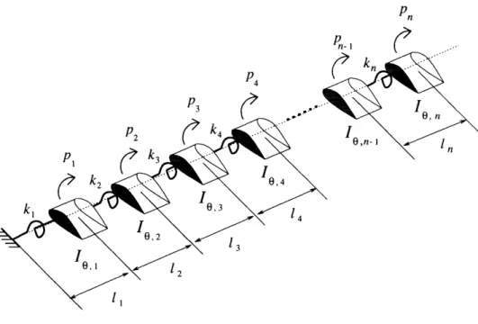
represent the stiffness and inertia coupling terms between arbitrary modes k and j. For a blade with spanwise-varying properties, a lumped parameter model may be
Pn P-In I P4 P3 P2 In PI 14 13 12 1l
Figure 2-5: Lumped torsional approximation of rotor blade.
employed. The rotor blade is approximated by a string of lumped inertias joined in series by torsional springs as shown in Figure 2-5. The mode shapes and natural frequencies are obtained by solving the following generalized eigenvalue problem
KCtO = W2M9ek (2.32)
where KC is the stiffness matrix and M i system. Defining the vector A,,
ak =
is the mass matrix of the lumped torsional
pl
P2
Pn k
(2.33)
problem for a lumped torsional system is explicitly presented as kl -k 2 -k 2 k + k2 - k3 -k 3
-.
kn + k_ -kn
-kn kn Pi P2 Pn kwhere Ie,i are the lumped pitch inertias and ki are them, defined as
GJ
ki= 1ii1 It,1 Pi 2 p WkIn. Pn
Jk
(2.34) the lumped torsional springs joining(2.35)
where Ii is the distance between adjacent lumped inertias. The eigenvectors 6,, and corresponding eigenvalues cw are the mode shapes and squared natural frequencies of this lumped parameter model. The kth modal stiffness and inertia for this lumped
system are
Kek
= GV46e
,
19k = 4T Mto .
(2.36) (2.37)
2.3.2 In Vacuo Equations of Motion
The equations of motion for pitch and flap motion are derived using Lagrange's method. The first step in the derivation is to define the components of the Lagrangian
L = T*-V,
(2.38)where T* and V are the kinetic and potential energies of the system.
Looking at a sectional slice of the rotor blade and assuming a chordwise mass distribution m., the sectional properties are
I =
f_
mx
2dx,
(2.40)
3
Xcg = mX nzdx. (2.41)
A thin airfoil is assumed so that property variations through the thickness are ne-glected.
The kinetic energy T* of the entire rotor blade is defined as
T*
= m,(V 2 + V22) d dr.
(2.42)
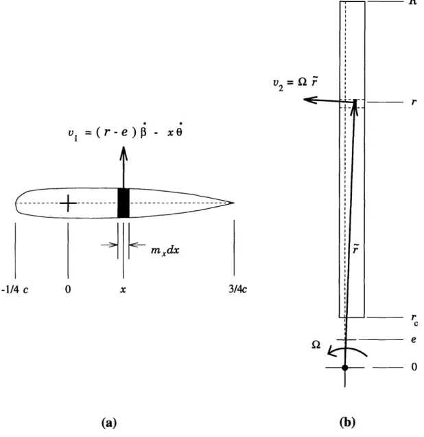
Only two velocity components of a differential chordwise element of mass, mmdx, will be considered. A component normal to the disk plane, vl, is due to the sectional pitch and flapping velocities. A radially tangential component, v2, parallel to the disk plane is the product of the angular velocity of the rotor, Q, and the radial position of the mass element, , dependent on the pitch and flapping coordinates. The velocity components are illustrated in Figure 2-6, and are given by
vl = (r - e) - = ,
(2.43)
V2 = Of, (2.44)
= ([e + (r- e) cos, + x sin sin ]2 + [X cos 0]2) . (2.45)
To simplify notation, the subscript k will imply a summation. Inserting the expres-sions for the velocity components (Equations (2.43) and (2.45)), and the pitch angle (Equation (2.22)) into Equation (2.42), and evaluating the chordwise integrals, the
v
1
=(r -
xOf -.E mxdx
x
Figure 2-6: Velocity components of differential chordwise element of mass:
(a) sectional view and (b) top view. V2= 2
f
Dr
r
C e 0 -1/4 c 0 3/4c (a) (b) ILkinetic energy is rewritten as
TV=
[m(r
-
e)2Mg2
-
-
e)r,
-
mxg(r
-
e)e
(r)ikf
+ -Ie6~ + I9to&(r)6kO
7 + -I9.Oe(r)6kI dr
2 r 2 '
+ R [me2
+
me(r -e)cos + mxcgsin(O,
+ oe,(r)Ok)sinB
1 1
+
m
-
e)
2os
2+
mxg(r -
e) sin
(,
+
ov
(r)6k)
sin 23
2 2
1 1 1
+ -Iosin2 (, +
o,(r)Ok)sin
23
-Iocos2(, +,(r)Ok)]Q
2dr (2.46)2 2
The potential energy of the rotor blade, which has contributions from the strain energy due to elastic twist and a flapping hinge spring, is given by
1 +lK
V = -Ko^k - K3,2, (2.47)
where K,3 is simply the hinge spring stiffness.
The equations of motion can now be derived for the kth torsional mode and rigid flapping dynamics using Lagrange's method. For convenience, the mode shape
6(r) = (r - e) will be used to represent the rigid flapping mode. Higher order terms will be neglected and small angle approximations will be used. Lagrange's equation for the elastic twist coordinate Ok is
dt --- = Nk. (2.48)
Assuming the modes shapes are orthogonal, the equation of motion for the kth tor-sional mode is
[
I
2o
dr k
+ dr m(jRIot9 W2+ Kak)
Ok]
+
[J.
Iele,, dr +
+R
dr'
Q29r]
Lagrange's equation for the rigid flapping coordinate is
dtq
(as)-~a,="
MF (2.50) and the equation of motion for rigid flapping is[j
m dr
3
+
(J
mrp dr
2
+ K)
P]
-[/
mxcgo dr Or
+
mxcgrdr
Q2r]
- [JR mxcgpge, dr k + mxcgr.e,(r) dr Sk] =
J
F
dr (2.51)The elastic twist and flap dynamics are structurally coupled by the center of gravity offset Xcg.
For convenience, the coupled dynamics may be non-dimensionalized and rewritten in matrix form. The resulting equations of motion are
E
1de-IokiX
1k
+
[Ie(
k
+1)
-Ila1f|k'l
L-Is /3 Ig3 2 L -Io + 1) IZj-2
It
e(
}
r + k+"}Or
+ ((2.52)
The nondimensional torsional frequency of the kth mode is defined as
Wk = K. (2.53)
Note that wk is the non-rotating natural frequency. The propeller moment, a centrifu-gal effect, stiffens the blade torsionally; hence the term (k + 1). The nondimensional flapping frequency is defined as
K
+
f
me(r - e)dr
(2.54)
frequency 0 when there is no flapping spring, K, or hinge offset, e. The non-dimensional mass and inertial integrals are defined in Appendix A.
Further pitch/flap coupling is introduced when the blade root configuration in-cludes a 83 hinge. The effect of the 63 hinge is a reduction in the apparent pitch angle
relative to the disk plane when the blade flaps up. This can be incorporated into the model by defining a coupling coefficient Kp = tan 63, so that
Oact = - KpPf. (2.55)
To implement this coupling effect, Equation (2.55) is simply substituted wherever 0r appears in the dynamics.
Transforming the matrix Equation (2.52) to MBC, the coupled equations of motion are
e
^
i°
(
| |+ [
hodei
|
0
'
+
[
|
Lp
APek
p
/3J
[
L
*k1 A,t p
J L
A
9,p
3 Ap
1 J113J[eips.
{r}
+
[
{
+
{
(2.56)
The various A matrices are defined in Appendix B, and are similar in form to the matrices derived in the MBC example. To complete the derivation, the aerodynamic forcing terms Nk and MF need to be evaluated. The aerodynamic forcing will introduce additional coupling between the rigid flapping and elastic pitch dynamics.
2.4
Aerodynamic Model
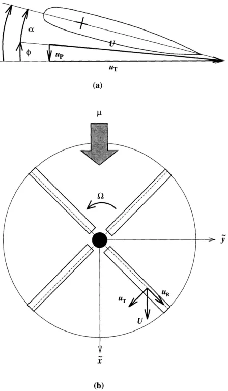
Several simplifying assumptions about non-linear effects and the unsteady aerody-namics have been made to produce a LTI rotor model. These assumptions will be discussed and the aerodynamic forcing terms will be derived and presented in the MBC frame. Before proceeding with the aerodynamic derivation, the nondimensional fixed and rotating frame velocity components will be defined.
![Figure 2-1: Block diagram of coupled rotor and inflow dynamics. Adapted from Pitt and Peters [35].](https://thumb-eu.123doks.com/thumbv2/123doknet/13844664.444279/34.918.201.765.117.541/figure-block-diagram-coupled-inflow-dynamics-adapted-peters.webp)