Design of a Robust PSS Using an Indirect Adaptive
Type-2 Fuzzy Sliding Mode for a Multi-Machine
Power System
K.Saoudi
Department of electrical engineering University of Bouira Bouira, Algeria Saoudi_k@yahoo.frZ. Bouchama
Department of sciences and technology University of Bordj Bou
Arreridj B. B. Arreridj, Algeria
M. Ayad, M. Benziane
Department of electrical engineering University of Bouira Bouira, AlgeriaM. N. Harmas
Department of electrical engineering University of Setif 1 Setif, AlgeriaAbstract—A new indirect adaptive type-2 fuzzy sliding mode controller as a power system stabilizer (PSS) is proposed for damping low frequency power oscillation of interconnected power system and capable of performing well for a wide range of variations in system parameters and/or operating conditions. The proposed controller design is based on the integration of sliding mode control (SMC) and Adaptive type-2 fuzzy control. The type-2 fuzzy logic system is used to approximate the unknown system function and PI control term is used to eliminate chattering action in the design of sliding mode control. Using Lyapunov stability theory, the adaptation laws are developed to make the controller adaptive to take care of the changes due to the different operating conditions occurring in the power system and guarantees stability converge. The robustness of the proposed stabilizer has been tested on a two-area four machine power system. Nonlinear simulation studies show the best performance of the proposed stabilizer and confirm its superiority over adaptive type-2 fuzzy synergetic (AFSPSS), adaptive type-2 fuzzy (AFPSS) and the conventional (CPSS) stabilizers.
Keywords— sliding mode control; PI control; type -2 fuzzy system; adaptive control; power system stabilizer
I. INTRODUCTION
Power systems are complex and highly nonlinear. The change in operating conditions will result in low frequency oscillations that may persist for long periods of time. In some cases, the oscillations will limit the power transfer capability. Power system oscillations are damped by the introduction of a supplementary signal to the excitation system called power system stabilizer (PSS). Early researches deal with lead-lag compensation as a conventional type [1, 2] which are tuned using a linear model of fixed power system in the specific operating point. However, the system dynamic response may regress when the operating point changes to some extent. In addition the power systems are highly nonlinear and the operating conditions could change over a wide range as a result of load changes, line switching and unforeseeable major disturbances such as three phase faults, adaptive controller designs based on nonlinear models are more promising. The basic idea behind adaptive techniques is to estimate the
uncertainties in the plant on-line based on measured signals [3,4]. However, adaptive PSSs can only deal with systems of known structure.
This problem is overcome by using artificial intelligence (fuzzy logic, neural networks) based techniques for the design of PSSs [5-8]. Fuzzy logic provides a tool for using human expert knowledge in additional to mathematical knowledge. It is a model-free approach, which is generally considered suitable for controlling imprecisely defined systems. The parameters of the fuzzy power system stabilizer are kept fixed after the design is completed. The performance of the fuzzy PSS depends on the operating conditions of the power system.
In the last decades, the merits of adaptive control and intelligent techniques such as fuzzy logic have been applied to the designs of adaptive stabilizing controllers [9-13]. Recently, in an effort to improve the robustness of the adaptive fuzzy power system stabilizer a research effort has been engaged in the design of adaptive fuzzy sliding mode controllers [14-16], which integrates the sliding mode controller design technique into the adaptive fuzzy controller design.
In this paper, an indirect adaptive type-2 fuzzy sliding mode power system stabilizer is designed to damp out the low frequency oscillations in power systems. It extends our work reported in [17]. The proposed stabilizer is initialized using the type-2 fuzzy logic system to approximate the unknown nonlinear functions of the power system model PI control term is used to eliminate chattering action in the design of sliding mode control. By the Lyapunov synthesis approach, adaptation laws are developed to make the fuzzy logic systems adaptive to change in the different operating conditions occurring in the power system. The simulation of the proposed stabilizers concept for a two-area four machine power system has shown that the performance of the adaptive type-2 fuzzy sliding mode power system stabilizer (AFSMPSS) is better than that of adaptive type-2 fuzzy synergetic (AFSPSS), adaptive type-2 fuzzy (AFPSS) and the conventional (CPSS) stabilizers.
II. POWER SYSTEM MODEL
expressed with a two-axis model [18] as in (1-5). 2 s d dt δ ω ω = − (1) 2 2 m e s H d P P dt ω ω = − (2) 1 ( ( ) ) d d q q q qo dE E x x I dt T ′ ′ ′ = − − − ′ (3) 1 ( ( ) ) q q d d d fd do dE E x x I E dt T ′ ′ ′ = − − − + ′ (4)
(
)
1 ( ) fd A ref t s fd A dE K V V U E dt =T − + − (5)In the design of the power system controller proposed in this paper, the dynamics model of generator can be expressed in the following nonlinear state-space equations:
1 2 2 1 2 1 2 1 ( , ) ( , ) x ax ax f x x g x x u y x = = + = ɺ ɺ (6) Where a= −1/ 2H , x1= ∆ = −ω ω ωs and 2 m e
x = ∆ =P P −P , H is the per unit machine inertia
constant,
ω
is the rotor speed andω
s is the synchronous speed are in per unit, Pm is the mechanical input power treated as a constant in the excitation controller design, i.e., it is assumed that the governor action is slow enough not to have any significant impact on the machine dynamics andP
e is the delivered electrical power. x =[
x x1, 2]
T ∈R2 is a measurable state vector. The PSS output u represents the controlling supplementary signal to be designed and y = ∆ω
is the output state while f and g are nonlinear functions which are assumed to be unknown. (Eq.6) represents the machine during a transient period after a major disturbance has occurred in the system.
III. SLIDING MODE CONTROL DESIGN
The control objective is to force y in the system (6) to track a given desired trajectory y . Then the control objective d
is determine a feedback control u u x= ( ) for the state y in the system (6) to track a given desired trajectory yd,
The elaboration of an indirect adaptive fuzzy sliding mode controller is presented in the rest of this section [14-16], to achieve the above control objectives is discussed.
Let the tracking error be defined as:
[ ]
, T de = −y y = e eɺ (7)
and a sliding surface defined as:
1
( ) T
s e =k e e+ =ɺ
k
e (8)Where
k
=[ ]
k1,1T are the coefficients of the Hurwitzian polynomial h( )λ = +λ k1. If the initial error vector e(0) 0= , then the tracking problem can be considered as the state error vector e remaining on the sliding surface s e( ) 0= for all0
t > . A sufficient condition to achieve this behavior is to select the control strategy such that:
2 1 ( ( )) 2 d S e s dt ≤ −η η >0 (9)
From (8) and (9), we have
1 ( ) ( ) d
.
s k e f xɺ= ɺ+ +g x u y−ɺɺ (10)
If f and g are known, we can easily construct the sliding mode control u* =ueq −usw :
[
]
* 1 1 ( ) ( ) sgn( ) d u = g− x −k e f x− −η s +y ɺ ɺɺ (11)[
]
1 1 ( ) ( ) eq d u =g− x −k e f xɺ− +yɺɺ (12)[
]
1( ) sgn( ) sw u =g− x η s (13)However, power system parameters for nonlinear functions are not well known and imprecise; therefore it is difficult to implement the control law (11) for unknown nonlinear system model. Not only f and g are unknown but the switching-type control term will cause chattering. An adaptive type-2 fuzzy sliding mode controller using type-2 fuzzy logic system and PI control term is proposed to solve these problems.
IV. INDIRECT ADAPTIVE IT2FUZZY SLIDING MODE
CONTROL DESIGN
If f and g were known, we could easily construct the
sliding mode control
u
*introduced in the previous section, however, f and g are not known, we thus replacef x t and ( , )( , )
g x t by the interval type-2 fuzzy logic system ˆf x( |θf ), ˆ ( | g)
g x θ which are in the form of (14-15) [19, 20].
(
)
ˆ ˆ 1 2 2 ˆ( | )= ( ) ( ) ( ) T T l r f fl l fr r T f f f f f x x x x θ θ ξ θ ξ θ ξ + = + = (14)(
)
ˆ ˆ 1 ˆ ( | )= 2 =2 ( ) ( ) = ( ) T T l r g gl l gr r T g g g g g x x x x θ θ ξ θ ξ θ ξ + + (15) to which we append a proportional integral PI control term to suppress the chattering action. The inputs and output of the latter are defined as1 2
p p i
u =k h +k h (16)
Where h1 =s, h2 =∫sdt, k and p ki are are PI control gains. (16) can be rewritten as
ˆ ( | p) Tp ( )
p h θ =θ ψ h (17)
2 , T
p k kp i R
θ =
∈ is an adjustable parameter vector, and ψT( )h =[
h h1, 2]
∈R2 is a regressive vector. We use interval type-2 fuzzy logic systems to approximate the unknown functions f x( ), g x( ) and design an adaptive PI control term eliminate chattering due to sliding mode control. Hence, the control law becomes:1 1 ˆ ˆ ( | ) ( | ) ˆ ( | g) f p d u k e f x p h y g x θ θ θ =
− ɺ− − + ɺɺ
(18)There for around the sliding surface, control law is introduced as. ( ) | | ˆ sgn( ) | | T p P h if s u s if s θ ψ ϕ η ϕ < = ≥ (19)
where is ϕ the thickness of the boundary layer. Using the control law in (18), then (10) becomes:
ˆ ˆ ˆ
( , ) ( | f ) ( ( , ) ( | g)) ( | p)
s f x tɺ= −f x θ + g x t −g x θ u p h− θ (20)
The next task, is to replace ˆf and ˆg by type-2 fuzzy logic systems represented in (14-15), ˆp is given by (17) and to develop adequate adaptation laws for adjusting the parameters vector θf ,θg and θpwhile seeking a zero tracking error. Using the procedure suggested in [28, 29], the parameter vectors of f xˆ( | )θf and ˆ( |g x θg)will be adapted according to the following rules.
Theorem 1. Consider the control problem of the nonlinear system (6). If the control (18) is used, if the interval type-2 fuzzy and PI are adjusted by the adaptive control law (21-25), the closed-loop system signals will be bounded and the tracking error will converge to zero asymptotically.
1 ( ) fl s fl x θɺ =γ ξ (21) 2 ( ) fr s fr x θɺ =γ ξ (22) 3 ( ) gl s gl x u θɺ =γ ξ (23) 4 ( ) gr s gr x u θɺ =γ ξ (24) 5 ( ) p s h θɺ =γ ψ (25)
Proof. Define the optimal parameters vector
* ˆ
arg min sup ( | ) ( , )
n f f f f x R f x f x t θ θ θ ∈Ω ∈ =
−
(26) * ˆarg min sup ( | ) ( , )
n g g g g x R g x g x t θ θ θ ∈Ω ∈ =
−
(27) * ˆarg min sup ( | )
n p p p p sw h R p h u θ θ θ ∈Ω ∈ =
−
(28)Where Ωf , Ωg and Ωpare constraint sets for θf ,θg
and θp, respectively. Define the minimum approximation error: * * ˆ ˆ ( , ) ( | f ) ( ( , ) ( | g)) f x t f x g x t g x u ε = − θ + − θ (29)
Assumption 1 The parameters θf ,θg and θpbelong to the constraint sets Ωf , Ωg and Ωp respectively, which are defined as
{
f n: f}
f θ R θ Mf Ω = ∈ ≤ (30){
g n: 0 g}
g θ R ζ θ Mg Ω = ∈ < ≤ ≤ (31){
p n : p}
p θ R θ Mp Ω = ∈ ≤ (32) fM ,
ζ
, Mgand Mp are positive constants designer specified for estimated parameters’ bounds. Assuming that fuzzy θf ,θgand PI control parameter θpdo not reach the boundaries.So, (20) can be written as
(
)
(
)
* 1 2 1 ( ) ( ) 2 ( ) ( ) ˆ ( ) ( | ) T T T T fl l fr r gl l gr r T p p u x x x x h p hs
θ ξ θ ξ θ ξ θ ξ φ ψ θ ε = + + + + − +ɺ
(33) Where φf =θ*f −θf , φg =θ*g −θg , φp =θ*p −θp. Now let us consider the Lyapunov function candidate2 1 2 3 4 5 1 1 1 1 2 4 4 4 1 1 4 2 T T T fl fl fr fr gl gl T T gr gr p p V s φ φ φ φ φ φ γ γ γ φ φ φ φ γ γ = + + + + + (34)
The time derivative of V along the error trajectory is:
1 2 1 2 3 4 3 4 5 1 1 ( ( ) ) ( ( ) ) 2 2 1 1 ( ( ) ) ( ( ) ) 2 2 1 ( ( ) ) sgn( ) T T fl fl fl fr fr fr T T gl gl gl gr gr gr T p p V s x s x s x u s x u s h s s s φ γ ξ φ φ γ ξ φ γ γ φ γ ξ φ φ γ ξ φ γ γ φ ψ φ η ε γ ≤ + + + + + + + + + − + ɺ ɺ ɺ ɺ ɺ ɺ (35) Where φɺfr = −θɺfr , φɺfl = −θɺfl , φɺgr = −θɺgr , gl gl φɺ = −θɺ and p p φɺ = −θɺ .
Substitute (21-25) into (35), then we have
0
Vɺ ≤sε−sη≤ (36)
Since
ε
is being the minimum approximation error, (36) is the best we can obtain. Therefore all signals in the system are bounded. Obviously, e t( ) will be bounded if e(0) is bounded for all t. Since if the reference signal y is bounded, then dsystem states x will be bounded. We need proving that
0
s → as t → ∞. Assuming that s ≤
η
s then (36) can be further simplified tos
Vɺ ≤ s ε −sη η ε≤ − sη (37)
Integrating both sides of (37), we have
0 0 1 ( (0) ( ) ) t t s s dτ V V t η ε τd η η ≤ + + ∫ ∫ (38)
then we have s L∈ 1. From (36), we know that s is bounded and every term in (33) is bounded. Hence, s s L, ɺ∈ ∞, use of
Barbalat’s lemma [21]. We have s →0 as t → ∞, the system is stable and the error will asymptotically converge to zero.
V. CASE STUDY AND SIMULATION RESULTS
For the study in this paper, the two-area four-machine test power system model [22] shown in Fig. 1 is selected for testing the performance of the designed PSSs using the proposed approach. This model consists of two fully symmetrical areas linked together by two transmission line of 220 km length. Each area contains two identical synchronous generators rated 20 kV/900 MVA. All generators are connected through transformers to the 230 kV transmission line and equipped with identical speed governors and turbines, exciters and AVRs, and PSSs. Under normal condition, the Area 1 transmits 400MW
active power to the Area 2. This power system typically is used to study the low frequency electromechanical oscillations of a large interconnected system.
Figure 1. Two area four machine test power system.
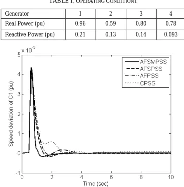
The performance of the proposed controller is evaluated by applying a large disturbance caused by a three-phase fault short circuit at the middle of one of the transmission lines between bus-7 and bus-8 at time t = 0.5 s. and cleared after t = 0.133 s. The fault is cleared without line tripping and the original system is restored upon the clearance of the fault. The system should be capable of appropriate performance on various operating conditions and can cause necessary attenuation during disturbances. In order to evaluate the performance of the proposed indirect adaptive type-2 fuzzy sliding mode power system stabilizer (AFSMPSS), the system response for two operation conditions is compared with is to those obtained using adaptive type-2 fuzzy synergetic (AFSPSS), adaptive type-2 fuzzy (AFPSS) and conventional (CPSS).To further assess robustness of the proposed PSS, performance index (
(
JP =∑t
∆ω)
|) is used to compare between the different PSSs considered.1) Operating condition 1
TABLE1.OPERATING CONDITION1
Generator 1 2 3 4
Real Power (pu) 0.96 0.59 0.80 0.78 Reactive Power (pu) 0.21 0.13 0.14 0.093
Figure 3. Response Gen2 for operating condition 1 .
Figure 4. Response Gen3 for operating condition 1 .
Figure 5. Response Gen4 for operating condition 1.
TABLE 2. COMPARING THE PERFORMANCE INDEX OPERATING
CONDITION 1 Operating
condition CPSS AFPSS Jp AFSPSS ASMPSS
Gen 1 195 77 72 43
Gen 2 195 84 62 36
Gen 3 204 92 76 32
Gen 4 201 88 74 32
2) Operating condition 2
TABLE3.OPERATING CONDITION 2
Generator 1 2 3 4
Real Power (pu) 0.56 0.92 0.56 0.61 Reactive Power (pu) 0.059 0.021 -0.018 -0.20
Figure 6. Response Gen1 for operating condition 2.
Figure 7. Response Gen2 for operating condition 2.
TABLE 4. COMPARING THE PERFORMANCE INDEX OPERATING
CONDITION 2 Operating
condition CPSS AFPSS Jp AFSPSS ASMPSS
Gen 1 223 145 104 47
Gen 2 214 150 123 58
Gen 3 234 166 128 44
Figure 8. Response Gen3 for operating condition 2.
Figure 9. Response Gen4 for operating condition 2.
As shown in the all figures for two operating conditions the one noted that, the damping stability is greatly improvement and steady state error when used AFSMPSS than used ASPSS, AFPSS and CPSS. The proposed stabilizer provides very good performance to change in operating conditions in terms of overshooting and settling time compared to the other PSSs.
VI. CONCLUSION
In this paper, a new an indirect adaptive type-2 fuzzy sliding mode power system stabilizer based for design on the approximation of unknown nonlinear function of synchronous machine using the type-2 fuzzy logic system and enhanced by a PI term controller that eliminates chattering in the sliding mode control signal. Adaptation laws are developed based on the Lyapunov synthesis approach.
It’s evident from nonlinear simulation studies that an adaptive type-2 fuzzy sliding mode power system stabilizer shows better performance in a wide range of operating conditions and system parameter variations, compared to adaptive type-2 fuzzy, adaptive type-2 fuzzy synergetic and conventional power system stabilizers counterpart by adding enough
positive damping in the power system thus rapidly suppressing power flow hindering low frequency oscillations.
REFERENCES
[1] E. Larsen and D. Swann. “Applying power system stabilizers”. IEEE Trans. Power Appl. Syst, vol. 100, no.6, p. 3017–46, 1981
[2] P. Kundur ,M. Klein ,G. J. Rogers and M.S. Zywno. “ Application of power system stabilizers for enhancement of overall system stability”. IEEE Trans. Power Syst.,vol. 4, no. 2, pp. 614–26, 1989.
[3] Y. Y . Hsu and K. L. Lious. “ Design of self-tuning pid power system stabilizers for synchronous generators”. IEEE Trans. Energy Conv., vol. 2, no. 3, pp. 343–348, 1987.
[4] S. Jain, F. Khorrami and K. Fardanesh. “ Adaptive nonlinear excitation control of power systems with unknown interconnections”. IEEE Trans. Control Syst. Technol., vol. 2, no. 4, pp. 1994.
[5] K. El-Metwally and O. Malik. “Fuzzy logic power system stabilizer”, IEE Proc. Gen. Trans. Distrib., vol. 142, no. 3, pp. 277-281, 1995. [6] K.A. El-Metwally, G.C. Hancock and O.P. Malik. “Implementation of a
Fuzzy Logic PSS Using a Micro-Controller and Experimental Test Results”. IEEE Trans. Energy Conv., vol. 11, no. 1, pp. 91–96, 1996. [7] P. Lakshmi and M. Abdullah Khan . “ Design of a robust power system
stabilizer using fuzzy logic for a multimachine power system”. Electr. Power Syst. Res., vol. 47, pp. 39–46, March 1998
[8] T. Hussein, A. L. Elshafei and A. Bahgat.“Design of a hierarchical fuzzy logic pss for a multi-machine power system”, Proc. of Mediterranean Conf. on Control and Automation, pages 1–6, 2007
[9] N. Hosseinzadeh and A. Kalam. ‘‘A direct adaptive fuzzy power system stabilizer’’. IEEE Trans. Energy Conv., vol. 14, no. 4, December 1999. [10] Saoudi, Z. Bouchama, M. N. Harmas and K. Zehar, ‘‘Indirect adaptive
fuzzy power system stabilizer’’, AIP Proc. of First Mediterranean Conf. on Intelligent Systems and Automation, vol. 1019, pp. 512-515, 2008. [11] A.L. Elshafei, K.A. El-Metwally and A.A. Shaltout. “A
variable-structure adaptive fuzzy-logic stabilizer for single and multi-machine power systems”, Control Eng. Pract., vol. 13, pp. 413-423, 2005. [12] T. Hussein, M.S. Saad, A.L. Elshafei and A. Bahgat. “ Damping
inter-area modes of oscillation using an adaptive fuzzy power system stabilizer”. Electr. Power Syst. Res., vol. 80, pp. 1428–1436, 2010. [13] Z. Bouchama, and M. N. Harmas. “Optimal robust adaptive fuzzy
synergetic power system stabilizer design”. Power Syst. Res., vol. 83, no. 1, pp. 170–175, 2012.
[14] K. Saoudi and M.N. Harmas, ‘‘Enhanced design of an indirect adaptive fuzzy sliding mode power system stabilizer for multi-machine power systems’’. Int. J. Electr. Power Energy Syst., vol. 54, no. 1, pp. 425–431, 2014.
[15] K. Saoudi, M. N. Harmas and Z. Bouchama, ‘‘Design of a robust and indirect adaptive fuzzy power system stabilizer using particle swarm optimisation’’. Energy Sources, Part A: Recov., Utiliz., Environ. Effects, vol. 36, no. 15, pp. 1670-1680, 2011.
[16] K. Saoudi, Z. Bouchama and M. N. Harmas, “An indirect adaptive fuzzy sliding mode power system stabilizer for single and multi-machine power systems”, Studies Comput. Intell., vol. 576, pp. 305-326, 2015 [17] K. Saoudi, M. N. Harmas, Z. Bouchama, M. Ayad and M. Rezki, “An
indirect adaptive type-2 fuzzy sliding mode pss design to damp power system oscillations”, 7th International Conf. Modelling, Identification Control, p.1-6, 2015.
[18] P. W. Sauer and M. M. Pai. Power System Dynamics and Stability, Upper Saddle River, N.J, Prentice Hall, 1998.
[19] J.M. Mendel, R.I. John and F. Liu. “Interval type-2 fuzzy logic systems made simple”, IEEE Trans. Fuzzy Syst., vol. 14, no. 6, pp. 808–821, 2006.
[20] J.M. Mendel, “ Advances in type-2 fuzzy sets and systems”. Inform. Sci. , vol. 177, pp. 84–110, 2007
[21] J.E. Slotine, W.P. Li, Applied Nonlinear Control, Prentice Hall, New Jersey 1991.
[22] Kundur P. Power System Stability And Control. New York: McGraw-Hill; 1994.