HAL Id: hal-01838581
https://hal.laas.fr/hal-01838581
Submitted on 13 Jul 2018
HAL is a multi-disciplinary open access
archive for the deposit and dissemination of
sci-entific research documents, whether they are
pub-lished or not. The documents may come from
teaching and research institutions in France or
abroad, or from public or private research centers.
L’archive ouverte pluridisciplinaire HAL, est
destinée au dépôt et à la diffusion de documents
scientifiques de niveau recherche, publiés ou non,
émanant des établissements d’enseignement et de
recherche français ou étrangers, des laboratoires
publics ou privés.
Fabrication and modeling of a capacitor microfluidically
tuned by water
Nizar Habbachi, Hatem Boussetta, Ali Boukabache, Mouhamed Adel Kallala,
Patrick Pons, Kamel Besbes
To cite this version:
Nizar Habbachi, Hatem Boussetta, Ali Boukabache, Mouhamed Adel Kallala, Patrick Pons, et al..
Fabrication and modeling of a capacitor microfluidically tuned by water . IEEE Electron Device
Letters, Institute of Electrical and Electronics Engineers, 2017, 38 (2), pp.277-280. �hal-01838581�
Abstract— This letter presents the fabrication and the
modeling of a continuously tuned microfluidic capacitor. On one hand its electrodes are realized by classical electrodeposition techniques and on the other hand, the lamination of SU-8 films allows superposing some microfluidic channels. According to the experimental results, the capacitor value increases continuously following the deionized (DI) water penetration in microchannels. The capacitance variations are comprised between Cmin = 0.52 pF
and Cmax = 18.5 pF, allowing a wide tuning range that reaches
3460% at 500 MHz. The quality factor decreases from Qmax = 69
when the capacitor is empty to Qmin = 5.3 when it is fully filled
with DI water. We have also investigated the theoretical aspects of our device by modeling the electric field and the current distributions inside the channels: when they are entirely filled with the DI water, the electric field is cancelled.
Index Terms—MEMS, capacitor, tuning, fluid
I. INTRODUCTION
Microfluidic MEMS are widely used to control the microwave devices in different configurations and many applications [1] requiring reconfigurability. The most used configurations are based on two complementary approaches: contact-based shortening [2] and contactless RF-shortening [3]. The common advantages of these microfluidic-based structures can be summarized as follows: low insertion loss, high power handling, high frequency response, and ease of fabrication. Nevertheless, the liquid movement in microchannels needs an actuation pump and a reservoir tank that leads to increase the size and the complexity of the structure.
In this letter we are interested by the contact-based RF-shortening. Our main idea is to change some RF characteristics of a microwave capacitor by using the deionized (DI) water as a dielectric. In the second section we present the layout and the
This work was initiated in the framework of the cooperation between DGRS (Tunisia) and CNRS (France).
N. Habbachi, H. Boussetta, M. A. Kallala, are with Microelectronics and Instrumentation Laboratory, Faculty of Sciences of Monastir, 5000 Monastir, University of Monastir, Tunisia, (e-mail: [email protected]; [email protected]; [email protected]).
K. Besbes is with the Center for Research on Microelectronics & Nanotechnology, CRMN Sousse TechnoPark, and he is with Microelectronics and Instrumentation Laboratory, University of Monastir, Tunisia, (e-mail: [email protected]).
A. Boukabache, P. Pons are with the Laboratory for Analysis and Architecture of Systems, CNRS, LAAS, 7 avenue du Colonel Roche, 31077 Toulouse, France, (e-mail: [email protected]; [email protected]).
fabrication of our structure with detailed dimensions. The third section summarizes the performances of the device for different positions of the DI water between electrodes. The distribution of the electric field and the current density in the structure allows understanding some particular phenomena. Hence, the presence of a fluid with high dielectric constant could cancel the prevailing electric field between the capacitor electrodes. Knowing that our approach allows to control the different positions of the DI water in the channels, it is easy to predict a capacitor’s range of values or to modify them on demand.
II. CAPACITOR DESIGN AND FABRICATION
The proposed structure is based on dual circular electrodes as shown on Fig. 1(a). This geometry has been used in microfluidic structures to control magnetic beads by modulating the magnetic field [4] and to vary the inductance value of a microwave coil [5].
(a)
(b) (c) (d)
(e) (f) (g)
Fig. 1: (a) Tridimensional view of the microfluidic capacitor and its cross section; the six fluidic positions in the channels: (b) POS1 (c) POS 2 (d)
POS3 (e) POS4 (f) POS5 (g) POS6.
Fabrication and modeling of a capacitor
microfluidically tuned by water
Nizar Habbachi, Hatem Boussetta, Ali Boukabache, Mohamed Adel Kallala, Patrick Pons, Kamel
Besbes, IEEE Member,
The dual circular electrodes present the following characteristics: W = 15 µm width, G = 20 µm gap, and the inner diameter close to ID = 200 µm. The different fluid positions studied in this work are indicated in Fig. 1(b-g). The microwave capacitor (Fig. 2(a)) is realized by using a mixed process: the structuration of the metallic electrodes is carried out by electrolytic growth and photolithography; on the other hand, the fluidic parts are obtained by laminating a patterned photoresist SU-8 film. The detailed fabrication process has been developed previously and applied successfully to other devices [5].
The cross section of the structure (Fig. 2(b)) allows to observe the rectangular aspect of microfluidic channels and to measure the height of the channels (CH = 50 µm) and their width (CW = 200 µm), with a separation of S = 100 µm. The used substrate is a glass Borofloat 33 (Br33) having H = 500 µm of height.
(a) (b)
Fig. 2: (a) Photography of the capacitor under test (b) cross section of the superposed layers constituting the capacitor device.
III. MEASUREMENT RESULTS AND DISCUSSION: The device is electrically characterized by using ground-signal-ground (GSG) probes and a vector network analyzer Agilent 8510.
A. Quality factor variation:
The quality factor of the passive components represents an important parameter for RF circuits as VCO, LNA, and filters. All these devices require a high quality factor in order to decrease their phase noise, insertion loss, and power consumption [6]. In our case, we study the influence of a particular fluid on the quality factor of our device. It will be measured for six particular positions of DI water present in the channel for frequency varying from 100 MHz to 10 GHz. The results reported in Fig. 3(a) show that the value of the quality factor decreases by following the DI water penetration in the micro channels. To highlight this influence, we have reported in Fig. 3(b) the quality factor variations at 500 MHz for each
0.1 1 10 0 10 20 30 40 50 60 Qua lity fa ctor Frequency (GHz) POS1 POS2 POS3 POS4 POS5 POS6 0 1 2 3 4 5 6 0 14 28 42 56 70 (b) (a) Qua lity f a c to r Position at 500 MHz
Fig. 3: Measurement of the quality factor of our device (a) in response of frequency (b) in response of DI water positions at 500 MHz.
of the DI water positions in the channel: it can be observed that it decreases continuously from Qmax = 69 when the
capacitor is empty to Qmin = 5.3 when the channel is full.
This result can be explained by the modification of the electric field in the channels: it is due to the presence of the DI water acting as a partial dielectric layer. To search possible improvements of our approach, we have used a finite element method tool (HFSS software) to model the electric field distribution in the channels for each of the six positions of DI water: the principal results are summarized in Fig. 4.
(a)
(b) (c) (d)
(e) (f) (g)
Fig. 4: Electric field distribution at 500 MHz for the different positions of water (a) POS0 (b) POS1 (c) POS2 (d) POS3 (e) POS4 (f) POS5 (g) POS6.
The first color map of the Fig. 4(a) shows the electric field distribution when the capacitor is empty. We can observe that the maximum electric energy is prevailing inside the micro channels namely between the electrodes. Knowing that the air permittivity is lower than the SU-8 one, the micro-channels represent the containment medium for the electric field. When we introduce the DI water between the capacitor electrodes, the electric field disperses into the SU-8 medium as shown in Fig. 4(b). Hence, we can observe in Fig. 4(c-f) that for the other fluid positions, the repartition of the electric field in micro-channels changes significantly. For the situation shown in Fig. 4(g) the capacitor device is fully filled with DI water, and we can observe that the electrical energy is transferred from the micro-channels medium to the whole structure in equiponderant way. These results can explain the drastic diminution of the quality factor of the device when the DI water occupies the different positions in the micro-channels.
B. Capacitance variations:
For each of the six positions of the DI water, we have carried out the capacitance measurements for frequency varying from 0.1 GHz to 4 GHz. The results reported on Fig 5 show similar behavior with noticeable changes in resonant frequencies from 690 MHz (POS 6) to 1.2 GHz (POS 1). 0.1 1 -40 -20 0 20 40 (b) (a) Frequency (GHz) Capa citan ce ( pF ) POS1 POS2 POS3 POS4 POS5 POS6 0 1 2 3 4 5 6 0 5 10 15 20 Capac iatanc e (pF ) Position at 500 MHz
Fig. 5. Measurement results of the capacitance value (a) in response of frequency (b) in response of DI water positions at 500 MHz.
It can be observed also that the capacitance value increases continuously with the presence of the DI water in the channels. To evaluate the span of the capacitance variations, we have reported on Fig. 5(b) its values at 500 MHz for the six positions of DI water: Cmin = 0.52 pF when the device is
empty; Cmax = 18.5 pF when it is fully filled. We obtain hence
a tuning range of Tr = 3460%, which is very high compared to Tr = 800% of the conventional switched capacitor [7]. In the literature, continuous MEMS varactors with TR of 2000-3000% have been reported [8-10] and the ability to reach such tuning levels is possible with microfluidic approach.
(a)
(b) (c) (d)
(e) (f) (g)
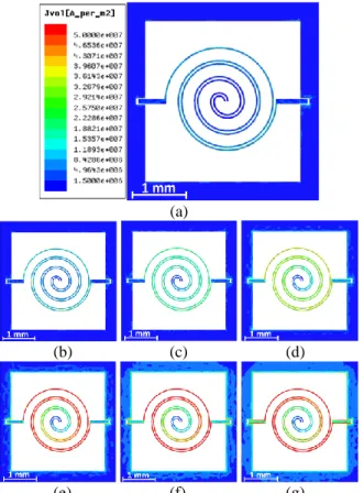
Fig. 6: Electric current distribution for the different DI water positions: (a) POS0 (b) POS1 (c) POS2 (d) POS3 (e) POS4 (f) POS5 (g) POS6.
To go further in the analysis, we have investigated the electric current density variations occurring at the electrodes surface for 500 MHz. As we can see on Fig. 6(a-d), the electric current density increases continuously in the capacitor electrodes in response to the DI water displacement and reaches its maximal value for the position POS4 (Fig. 6(e)). Furthermore, one can observe in Fig. 6(e-g) that the electric current density continues to increase on the electrode surface used as electrical ground according to the water positions. These observations could explain the increase of the capacitance value in response of the DI water displacement.
C. Insertion loss variations:
In order to evaluate the influence of the DI water displacement on the insertion loss (IL) response, we reported in Fig. 7 the measurement results of the transmission gain at the frequency range from 100 MHz to 3 GHz for the six DI water positions.
0.5 1.0 1.5 2.0 2.5 3.0 -6 -5 -4 -3 -2 -1 0 (a) Frequency (GHz) (b) S21 (d B) POS1 POS2 POS3 POS4 POS5 POS6 0 1 2 3 4 5 6 -20 -16 -12 -8 -4 0 In se rtio n lo ss DI water positions
Fig. 7. Measurement results of : (a) S21 gain in response of frequency ; (b) insertion loss in response of DI water positions at 500 MHz.
We can conclude from the reported results in Fig. 7(a) that the microwave capacitor acts as a tunable bandpass filter following the DI water displacement. The frequency band is larger when the capacitor is empty and decreases with DI water penetration in microchannels. In addition, we have collected the insertion loss value at 500 MHz for each DI water position as illustrated in Fig. 7(b). It is obvious that the insertion loss decreases from IL = -18.63 dB at (POS0) to IL = -0.44 dB when the capacitor is fully filled (POS6). These results reveal the importance of DI water that improves the transmission gain of the microwave capacitor.
IV. CONCLUSION
This letter investigates the effect of a dielectric fluid as DI water on the tunable capacitor performances. We have designed and fabricated a dual spiral capacitor by using a microfluidic based structure. The capacitance value is minimal when the structure is empty (Cmin = 0.52 pF) and increases
continuously with DI water penetration in microchannels to reach Cmax = 18.5 pF. We obtain a high tuning range Tr =
3460% whereas the quality factor decreases from Qmax = 69 to
Qmin = 5.3. The associated modeling allows to explain the
cancellation of the distributed electric field in the micro channels and the increase of the current density in the electrodes in response to the DI water displacements. In the future, this theoretical investigation would be useful to explain the experimental results and to predict the response of microwave devices using dielectric fluids.
REFERENCES
[1] K. Entesari and A. P. Saghati, “Fluidics in Microwave Components,”
IEEE Microwave Magazine, vol. 17, no. 6, pp. 50-75, 2016. DOI:
10.1109/mmm.2016.2538513.
[2] Y. Kondoh, T. Takenaka, T. Hidaka, G. Tejima, Y. Kaneko, and M. Saitoh, “High-reliability, high-performance RF micromachined switch using liquid metal,” IEEE J. Microelectromech. Syst., vol. 14, no. 2, pp. 214–220, Apr. 2005. DOI: 10.1109/jmems.2004.839604.
[3] A. J. King, J. F. Patrick, N. R. Sottos, S. R. White, G. H. Huff, and J. T. Bernhard, “Microfluidically switched frequency-reconfigurables slot antennas,” IEEE Antennas Wireless Propagat. Lett., vol. 12, pp.828– 831, 2013. DOI: 10.1109/lawp.2013.2270940.
[4] R. Fulcrand, D. Jugieu, C. Escriba, A. Bancaud, D. Bourrier, A. Boukabache, and A. M. Gué, “Development of a flexible microfluidic system integrating magnetic micro-actuators for trapping biological species,” J. Micromech. Microeng., vol. 19, no. 10, p. 105019, 2009. DOI: 10.1088/0960-1317/19/10/105019.
[5] I. El Gmati, P. F. Calmon, A. Boukabache, P. Pons, R. Fulcrand, S. Pinon, H. Boussetta, M. A. Kallala, and K. Besbes, “Fabrication and evaluation of an on-chip liquid micro-variable inductor,” J. Micromech.
Microeng., vol. 21, no. 2, p. 025018, 2011. DOI: 10.1088/0960-1317/21/2/025018.
[6] H.-C. Chen, C.-H. Chien, H.-W. Chiu, S.-S. Lu, K.-N. Chang, K.-Y. Chen, and S.-H. Chen, “A low-power low-phase-noise LC VCO with MEMS Cu inductors,” IEEE Microwave and Wireless Components
Letters, vol. 15, no. 6, pp. 434-436, 2005. DOI :
10.1109/lmwc.2005.850565.
[7] D.-H. Baek, Y. Eun, D.-S. Kwon, M.-O. Kim, T. Chung, and J. Kim, “Widely Tunable Variable Capacitor with Switching and Latching Mechanisms,” IEEE Electron Device Lett., vol. 36, no. 2, pp. 186-188, 2015. DOI: 10.1109/led.2014.2378272.
[8] H. Nguyen, D. Hah, P. Patterson, R. Chao, W. Piyawattanametha, E. Lau and M. Wu, “Angular Vertical Comb-Driven Tunable Capacitor With High-Tuning Capabilities,” IEEE J. Microelectromech. Syst., vol. 13, no. 3, pp. 406-413, 2004. DOI: 10.1109/jmems.2004.828741. [9] C. Lee and E. Kim, “Piezoelectrically Actuated Tunable Capacitor,”
IEEE J. Microelectromech. Syst., vol. 15, no. 4, pp. 745-755, 2006.
DOI: 10.1109/jmems.2006.878886.
[10] S. Pu, D. Darbyshire, R. Wright, P. Kirby, M. Rotaru, A. Holmes and E. Yeatman, “RF MEMS Zipping Varactor With High Quality Factor and Very Large Tuning Range,” IEEE Electron Device Lett., vol. 37, no. 10, pp. 1340-1343, 2016. DOI: 10.1109/led.2016.2600264.