HAL Id: hal-01759061
https://hal.laas.fr/hal-01759061
Submitted on 5 Apr 2018
HAL is a multi-disciplinary open access
archive for the deposit and dissemination of
sci-entific research documents, whether they are
pub-lished or not. The documents may come from
teaching and research institutions in France or
abroad, or from public or private research centers.
L’archive ouverte pluridisciplinaire HAL, est
destinée au dépôt et à la diffusion de documents
scientifiques de niveau recherche, publiés ou non,
émanant des établissements d’enseignement et de
recherche français ou étrangers, des laboratoires
publics ou privés.
An overview of humanoid robots technologies
Olivier Stasse, Thomas Flayols
To cite this version:
Olivier Stasse, Thomas Flayols. An overview of humanoid robots technologies. Biomechanics of
Anthropomorphic Systems, Springer, pp.281-310, 2019, 978-3-319-93870-7. �hal-01759061�
O. Stasse1and T. Flayols1
Abstract Humanoid robots are challenging mechatronics structures with several interesting features. Choosing a humanoid robot to develop applications or pursue research in a given direction might be difficult due to the strong interdependence of the technical aspects. This paper aims at giving a general description of this inter-dependence and highlight the lessons learned from the impressive works conducted in the past decade. The reader will find in the annex a table synthesizing the char-acteristics of the most relevant humanoid robots. Without focusing on a specific application we consider two main classes of humanoid robots: the ones dedicated to industrial application and the ones dedicated to human-robot interaction. The tech-nical aspects are described in a way which illustrates the humanoid robots bridging the gap between these two classes. Finally this paper tries to make a synthesis on recent technological developments1.
1 Mechanical structure
1.1 General design principal
Humanoid robots are complex mechatronic systems. As such, it is necessary to con-sider the the mechanical structure, the computational system and the algorithms as a whole and for a given application. The robot’s size, weight and strength are im-portant factors when designing its structure. Let us consider two general classes of applications: physical performances while doing motion generation and validation of biological and/or cognitive models. The ATLAS robot from Boston Dynamics is an example of the first category, while the Kenshiro robot [45] from Tokyo Univer-sity is an example of the second category.
CNRS - LAAS1, Toulouse, France, first name.family [email protected] 1This contribution is a translation and a revision of [58]
When the goal is to have a robot with walking speed performances around 2 to 3 km/h, the knowledge from walking robots such as HRPs robots from Kawada In-dustries or the LOLA robot from the Technological University of Munich, shows that there are two mechanical points to take into account [41]: the mass distribution on one side, and the undesirable mechanical resonances on the other. The last point implies to suppress compliance at the level of the joints and the links. For this rea-son, most of the humanoid robots are very rigid in order to achieve a high precision control. When the human-robot interaction is a major constraint during the design phase, the control precision is not the main objective. The security level necessary to allow a physical interaction with a human is then obtain by introducing actuators with low power and flexible mechanisms in the transmissions, such as the one de-scribed in paragraph 3. There exists robot designs which try to synthesize several constraints with more specific objectives. For instance, the HRP-4 humanoid robot is lighter (39 kg) for a size of 1.5m with 34 degrees of freedom (DoFs). This is the result of a compact power electronics and a skeleton made of carbon fiber. The drawback is that the robot segments are more flexible and the low power actuators limits the load that the robot can hold.
1.1.1 Mass distribution
Balance is an example of relation between control, computing capabilities and the mechanical structure. For walking robots evolving on flat floors, the main criteria for balancing is the point on the ground where there is no angular momentum. This point is called the Center-Of-Pressure (CoP). To maintain the balance of a humanoid robot evolving on flat ground, it is necessary to find in real time a control allowing to keep the CoP inside the convex hull of the contacts points on the ground. To solve the associated control problem in an efficient way, it is usually assumed that the robot is behaving like a point mass model. This assumption is valid when the robot limbs are light, and when the mass distribution is concentrated on the waist. The Center-Of-Mass (CoM) is then globally fixed with respect to the waist. When this assumption is not valid, then the control needs to use more complex models which are more difficult to solve. More precisely, the controllers then need to consider a three mass model when the legs masses are not negligible, or a five mass model if the arms are too heavy as well. Such models need more complex control techniques. For instance the team from the Technological University of Munich had to redo a design phase with its walking robot LOLA to improve the mass distribution [41].
The mass distribution depends mainly on the actuators. To limit their inertial ef-fects on the robot dynamic, it is mandatory to bring the actuator as close as possible to the root of the link on which it is fixed. To transmit the motion to the joints, various mechanisms can be used: lever, ball-screw, pulleys with driving bells. For instance LOLA is using levers [41], while HRP-4 is using ball-screw for some joints and pulleys for others[32].
1.1.2 Human robot interaction
Human robot interaction implies to control the robot forces for safety. This can be done in an active manner (using a feedback loop) or passively (by mechanical de-sign). Robots with high gains controlled actuators are not able to estimate correctly the forces applied by a human. If performance is still the main objective, it is better to integrate at an early stage supplementary sensors (force sensors or artificial skin cf paragraph 4) at high frequency (1 kHz) as it is done for the Kuka LWR robot. Another approach consists in using servomotors with which it is possible to lower the gains and hence to allow the actuator to be compliant. This strategy is used for instance by the Poppy robot [39].
1.1.3 Mechanical resonance
Mechanical resonance consists in vibrations of the robot mechanical structure re-lated to the link deformation (for instance the legs) or the actuators control. As specified before, this passivity might be desired to perform human robot interaction. It can be mechanically integrated by the actuators to reject impacts as it is done in the COMAN humanoid robot at the IIT [65]. It might be undesired and be the consequences of design constraints such as for HRP-4 [32]. In all these cases, it is strongly advised to perform a frequency analysis of the system when it is possible. The team of the LOLA robot [41] realized analysis for each link to detect the weak-ness of some pieces such as the hip and the knee to avoid undesirable deformation. It is possible to use beam theory on the femur and the tibia to evaluate the leg de-formation when it is exposed to strong torques and forces. For tall robots (1.6 m to 2 m), not handling properly the passive dynamic might induce strong impacts during the landing phase [26].
1.1.4 Estimating the leg deformation
It is possible to use beam theory to evaluate the link deformations and the system natural frequencies. A link submitted to a load q has the following dynamics:
∂2 ∂ x2(EI ∂2u ∂ x2) + ρA ∂2u ∂ t2 = q (1) with E the material Young modulus, I the second order moment of area of the link’s cross-section, ρ the material density, A the section surface, u and x respectively the deflection and its position along the static axis. In the case of an homogeneous beam of size L, parameters E, I, ρ and A are constants. If we consider the natural frequencies when there is no load, we solve the previous differential equations by using the Fourier Transform. The frequency is therefore:
ω= λ2 s
EI
ρ AL4 (2)
and the solution can be written as:
v(x,t) = ¯v(x)sin(ωt) with ¯
v(x,t) = A1sin(β x) + A2cos(β x)+ A3sinh(β x) + A4cosh(β x) β= nπ, λ = Lβ
where A1, A2, A3, A4are constants. The objective is to maximize this frequency to avoid the one occurring during the application. However only the section and the moments surface can be changed. The coefficient E/ρ suggests materials with very high rigidity such as carbon fiber. The beam geometry is represented by I/A. This ratio is maximal for a geometry with high second order moments with respect to the small transverse sections.
1.2 Robot skeleton
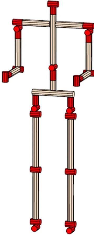
The kinematic structure of humanoid robots has long been inspired by the human structure, and more precisely based on the study of Saunders [54]. For this reason, numerous humanoid robots have the structure depicted in Fig.1. The legs are made of 3 rotation joints at the hip level (to simulate a spherical joint), one joint for the knee flexion-extension and two joints for the ankle (flexion-extension and prono-supination). This structure has one advantage: it has an analytical solution to the problem of finding a configuration for the legs with respect to a given position of the waist and the feet. For all these reasons, it is find in numerous robots such as the HRPs series, HUBO[40], ASIMO and REEM-C. The counterparts of this struc-ture are the performance limits in the kinematic chains. Adding a passive toe joint allows to increase the robot walking speed [56]. To limit singularities and kinematic constraints, recent humanoid robots such as S-One from Schaft or ATLAS have more joints. For instance, Schaft as one more DoF on its legs on the sagittal plane. More generally in the context of the DARPA Robotics Challenge (DRC) [11], RO-BOSIMIAN from JPL [36] and CHIMP [60] from CMU are ape-like robots which allow to perform more extended locomotion modes than bipedal ones. S-One has highly redundant arms which permit to avoid singularities and kinematic limits. In a general manner, if dexterity is a primary objective, it is strongly advised to use an arm with 7 DoFs to avoid singularities. This has however a direct impact on the number of motor and therefore on the arm mass, its electronic complexity and the its weakness.
Fig. 1 Classical structure of a humanoid robot
1.3 Grippers
Grippers for humanoid robots should be chosen according to the application. It is necessary to find a compromise between dexterity and the load that the hand can carry. A dexterous hand allowing fine manipulation such as the one of the DLR [5] involves a structure with the same numbers of DoFs than the whole robot skele-ton. For instance, the complex hands developed by the Japanese National Institute of Advanced Industrial Science and Technology (AIST) [30] for the HRP-3 have 3 fingers and 3 DoFs by fingers, with a thumb of 4 DoFs. This hand is equipped with force sensors at each finger. The fingers are allowing a maximal push of 15 N thanks to a mechanical structure using motors and Harmonic Drive (HD). If aesthetic cri-teria are important, one has to take into account the proportion of the hand size with the rest of the body [33]. For instance, the DLR hand is too long and too big to be integrated in a robot such as HRP-2. The challenge is to integrate motors, cables and
power electronics in the forearms. For this reason, the AIST hand is provided with a box at the wrist. It contains an embedded computer for the control which limits the cabling to be added to the initial structure. The box is also used to protect the hand (it is the same protection that is used for the Q-RIO robot). This, however, increases the weight at the robot arm extremity and needs to be taken into account in the robot dynamics. Complex hands with several DoFs are heavier, take more space but are also more fragile, and, at the same time, can not lift up an heavy load. ASIMO, in its initial version, could not take a load heavier than 500 g [30]. Another example of complex hand is the one developed for iCub [55]. It has 19 DoFs, touch sensors and can perform complex manipulation. For all these reasons, simpler grippers can be chosen. For instance, the gripper used by the humanoid robot HRP2-Kai [34] can be used to climb a ladder. The humanoid robot TALOS [59] is able to handle 6Kg while stretching its arm. The humanoid robot HRP-2 is able to sustain 15 Kg forces during multi-contacts walking [8]. Under-actuated hands are a frequent choice which sim-plifies the control and the actuation, with a slightly more complex transmission. For instance, the HRP-2 from Tokyo University and AIST are equipped with a parallel mechanism using one DoF. It is less dexterous but it enables the manipulation of thirty different classes of objects with masses up to 5 Kg. Robots such as NAO are using a single DoF by hand, all the fingers are folding or unfolding together at the same time. This kind of grasp provides an automatic adaptation to the object shape. The last version of the humanoid robot ASIMO is integrating hands with hydraulic actuators of small size directly mounted in the forearm. With such hands, the robot can pereform complex motions such as opening a thermos and pour water in a glass.
Fig. 2 Non-planar contacts to extend the reachable space (left) [37] and to perform generalized locomotion (right) [8]
1.4 Mobility
There exists a certain number of robots qualified as ”humanoids” for which the lower part does not use two legs but a mobile platform or a higher number of legs. A famous robot in this category is the PR-2 robot from the former company Willow Garage. Other famous robots with the same structure are the ARMAR series, and the REEM-B from PAL-Robotics. The former is able to recognize objects, to ma-nipulate them, and for instance to put them in a dishwasher. Such robots are very efficient for mobile manipulation. When the mass to manipulate is too big with re-spect to the part of the robot in contact with the ground, the dynamical effects need to be taken into account. The balance problems handled by humanoid robots and for instance the angular momentum regulation are the same in this context. However re-cent advances on multi-contacts generation show the possibility to generate motions which are outside the scope of the ones using a mobile platform (Fig. 2). HRP-2 is also able to make contact with a desk to expand its workspace and reach another target. If such motion can be planed, only recently they can be generated on line. The multi-contact problem has a very high complexity in its general formulation. It exists some efficient approximations but which have not yet been implemented on a physical robot. If the DRC has shown the possibility for the robots such as S-One to handle complex environments, most of the contacts are planar (but not necessary in the same plane). This is possible thanks to a robust control of the CoP able to handle slope variations of 10 degrees.
1.5 Foot
Feet are very important for humanoid robots: they must insure a contact with suffi-cient friction to avoid slippage; they must handle impacts during landing; they must handle contact transition during the double support phase; finally their mechanical structure is often constrained by the size. In addition as most of the humanoids are walking by controlling their CoP, it is necessary to have 6 axis force sensors at the ankles, or pressure sensors under its feet to measure the CoP Position.
To avoid robot slippage, humanoid robots have soils with shapes and materials which provide a sufficient friction (typically with a friction coefficient > 1).
To dissipate impacts, the LOLA robot [41] for instance is using Sylomer with an elastic modulus higher at the heel and smaller for the rest of the foot. Some feet include dampers [41] [46].
Toe joints do have numerous interests. They enable the transfert of the CoP quickly to the front, and thus make the robot walk faster than a structure without toe-joint [56]. They are allowing the robot to kneel without being in a singular po-sition at the foot level. Finally if we add a spring to the toe-joint, it is possible to store energy to use it during the take-off phase or to make the robot step on the spot [27]. This implies a more complex control. One needs to insure that the mobile part is able to handle the impacts.
1.6 Constraints from the environment
Using humanoid robot in industrial environments may expose them to dust, humid-ity or even rain. The HRP-3 humanoid robot has been designed to face such con-straints [31]. It is compatible with norm IEC-IP52 (International Electrotechnical Commission, Ingress Protection). The first number means that the system is pro-tected against dust which would keep the robot from working properly. The second number expresses a protection against vertical rain. This protection level has been obtained thanks to tests on the HRP-2 actuators. To track the actuator weakness, dust resistance has been tested with talc, while water resistance was tested with flu-orescent liquid. The robot has been reinforced through sealed ball bearings, liquid, torques and silicon joints.
Joints Motor Actuator Reduction Joint limit Max
veloc-ity (/s) Torque (N.m) toe M20 PG+EDD 177 -60 15 441 56 ankle - R M90 TB+HD 121 -35 30 433 91 ankle - P M90n HD 121 -90 90 433 91 knee - P M150 HD 161 0 150 283 144 hip P M90 TB+HD 181.5 -135 40 289 143 hip R M90 TB+HD 180 -35 30 291 142 hip Y M20 HD 120 -30 90 650 38 shoulder Y M90 HD 120 -90 0 437 94 shoulder P M90 HD 120 -180 90 437 94 shoulder - R M90 HD 120 -30 100 437 94 elbow - P M90 HD 120 -140 0 437 94 wrist Y M20 PG+TB 118 -150 120 661 37 wrist R M20 TB+HD 137.5 -90 90 567 44 finger R M5 VSF+EDD 125 -65 30 696 48 neck P M20 TB+HD 150 -60 60 520 48 neck - Y M9 HD 50 -90 90 1198 N/A
Tableau 1 TB: Timing Belt, HD: Harmonic Drive, IS: Infinite screw, G : Gear, PG : Planetary Gearset. The data comes from the robot H7 of Tokyo University [21]. Motors M150, M90, M20, M5 are respectively the Maxon motors 148877, 118778, 118754, 118736. The motor M9 is a HD system RH8C-6006.
2 Computational structure
2.1 Embedded computer
Currently, control laws used to maintain a humanoid robot balance needs power-ful computational capabilities which are not available on CPU without acceleration mechanisms. For instance, the HRP-4 robot from Kawada Robotics is using a
Pen-tium M at 1.6 Ghz which is not equipped with the Intel Turbo Boost technology in contrast with processor i7 − 2710QE which can be found in the REEM-C humanoid robot. This technology makes it possible to increase the CPU internal clock accord-ing to the current kind of operations (mathematical for instance) and accordaccord-ing to the CPU temperature. The embedded motherboard has been chosen according to temperature tests made on the robot. Bigger robots are able to embed bigger moth-erboards equipped with powerfull CPU. Some care is however taken to avoid high heat dissipation. It is recommended to have enough space to have powerful CPUs which can be updated easily. This is for instance the case for the TALOS robot which has all his computers on one box which can be easily changed.
2.2 Communication buses
Communication buses are a very important component of humanoid robots. They can limit the control bandwidth available on the robot. They need to be extremely robust to electromagnetic perturbances. For this reason, it is strongly advised to have a bus with a high bandwidth to comply with hard real-time constraints. How-ever, depending on the data type, such constraints might be hard to fulfill or have a different nature. For instance, in control, deterministic dead-line are of primary im-portance. However in vision, the throughput is of utter imim-portance. For all these rea-sons, the communication structure may have multiple layers. For instance we may have PCI/PCI104/PCIe for the connection between the motherboards, the network cards and the analog/digital converter boards. To have a strong connection between the motors and the encoders, it is necessary to have very robust buses. Typically the ones from the automotive industry are used such as CAN (HRP3, iCub, HUBO-2) or EtherCAT (Pyrene, ATLAS, WALKMAN). However, CAN has a limited band-width (1Mbit/s) and does not allow to handle multiple point to point connections. Therefore humanoid robots often use several buses (HPR3, iCub). In order to solve this problem, the SERCOS-III protocol has been chosen by the robot LOLA [41]. This protocol has the following advantages:
• transmission by Quality of Service which reserve bandwidth to prevent colli-sions;
• higher efficiency during the transmission, obtained by using ASICS to control the buses and by using optic fiber as the physical support. SERCOS III extend this approach to Ethernet but it implies to have a switch for each node;
• Data transfer in real-time and in none real-time; • Connection possible between slaves;
• Connection to proprietary devices by adding fields to the data packets (force sensors, inertia measurement system).
2.3 Wireless communication
Wireless communications are generally handled by 802.11a/b/g/n switches. The last letter specifies the protocol version. These protocols match various frequencies. The latest (g/n) correspond to higher frequencies and are allowing higher bandwidths. For instance with protocol 802.11 it is possible to transmit uncompressed VGA im-ages at 10 Hz on WIFI using a 5 GHz frequency. However wireless communications main weakness is their sensitivity to environment where frequency overloading is possible. This is typically the case in events with a large public. In this case, people with their smartphone are overloading the network. This can be handled by carefully analyzing the frequency which can be used in the context of the robotic application.
2.4 Middleware
Middleware : A middleware is a software framework which enables distributed processes to exchange data on heterogeneous platforms. This ”software bus” uses an object map to offer a simple and coherent interface to access objects and to guarantee data transmission.
In humanoid robotics, there are three well known middlewares: ROS, YARP and OpenRTM (Corba). There exists other middleware such as NAOqi from Softbank Robotics. However, nowadays, ROS has the leading position. It is due to a large support from the robotics community which permits to quickly have access to in-novative algorithms for 3D reconstruction (KinFu, Octomap) or motion planning (OpenRave, OPMPL) and to system simulator such as Gazebo.
Middlewares propose a client-server architecture communicating by messages. Data types are usually specified through an Interface Description Language.
2.4.1 ROS
ROS (Robot Operating System) exchanges data by subscription and publication at frequencies up to 100/200 Hz. For static or rarely changing data, another system called parameter server is used. An application is a graph of nodes communicating through topics. Each node provides or consumes data (or both) and can also provide services. The interface to these services is also specified by an interface description language. From a functional point of view, ROS provides a package system which simplifies the creation and handling of packages. A build farm system provided by the Open Source Robotics Foundation (OSRF) creates binary packages from the source codes provided by contributors. This results in a better diffusion of the software created by the community.
ROS is supported in a stable manner on Ubuntu, but there exists also experimen-tal versions on Mac OS X, Windows and other distributions on Linux. Moreover, the sources of core components are available to adapt to other operating system. The
main inconvenient of ROS is its lack of real time capabilities. It is often necessary to use an additional middleware. The most used open source solution is OROCOS with Xenomai. This solution is implemented on the robot REEM-C. ROS is a very active project and is supported by the Open Source Robotics Foundation. The most com-mon software license used in ROS is BSD2. However, to provide a solution which can be deployed in factories, a group of industrial are working together to propose a certified solution.
2.4.2 OpenRTM
OpenRTM(Open source Robotic Technology) is a middleware designed and de-veloped by the AIST at the same time than the humanoid robot series HRPs [3]. OpenRTM is an implementation of the Robot Technology Components standard validated by the Object Management Group (OMG). OpenRTM is more oriented towards real-time application. The standard formalizes the messages sent between the components as data-flow. It is possible to specify the scheduling class of one software component. For instance, a component providing sensor data is specified as being periodic at the reading frequency of the sensors. This specification can be used to prove Real Time Quality of Service (if this is feasible on the platform). The data used in the control part of the application is specified as ports. Output ports correspond to data provided by the component, input ports are data that are needed by the components. It is also possible to access components in an asynchronous manner through services (like ROS). The data and the service calls are formalized by an Interface Description Language. As OpenRTM is based on CORBA, it relies on its tools. The OpenRTM community is mostly Japanese. The ecosystem includes the OpenHRP simulator, the human-robot interaction package OpenHRPI and a set of software support named OpenINVENT. However this project does not seem to be very active anymore. Most of the OpenRTM real-time components are implemented directly using the real time operating system. We can notice however that in the case of the robots HRPs, OpenRTM is delivered with a balancing component, a walking pattern generator and a simulator quite realistic. For instance the DLR biped robot TORO, uses OpenHRP for simulation.
2.4.3 YARP
The goal of YARP (Yet Another Robot Platform) [17] is to provide a message trans-mission system through ports by using different protocols and between machines with various operating systems. This is achieved by abstracting the communications as do CORBA and ROS, and by using libraries such as ACE to abstract the operating system functionalities (process, threads, file access, timers). It is worth noting that ACE, developed by the group implementing TAO, a real-time middleware, is also
2BSD : Berkeley Software Distribution License is a very permissive free license used quite a lot
used by OpenRTM. The interface with different languages is performed thanks to SWIG which enables to generate the various wrappers. Hence YARP is compatible with Linux, MAC OS, Windows and can be interfaced with numerous languages (http://www.swig.org). The data port concept exists in YARP as well as the object directory to localize object over a distributed architecture. Interacting with the hard-ware is possible through the specialization of an abstract DeviceDriver. With this mechanism, YARP supports various hardware without propagating their specificities over the software infrastructure. This integration is handled through the components in other robotics middlewares.
To conclude this part, OROCOS is a middleware used mostly to encapsulate the real-time interface of robots and is often found in conjunction with ROS.
3 Actuators
Actuators for humanoid robots need to fulfill the following criteria: a high ratio between power and mass, the capability to produce high torques at low speed, a relatively small size and back drivability. This part describes various technologies developed for humanoid robots.
3.1 Actuators with electric DC motors
Humanoid robots of human size, such as the HRP-2 humanoid robot, Johnny or HUBO-DRC are using DC electric motors with Harmonic Drives (HD) to transform speed into torque. Recent work on finding appropriate motors and reduction ratio can be found in [68] using the an upper and a lower bound on the inertia of the robot. The highest angular momentum take place at the level of the hip and the knee. For this reason, in the case of the Walkman robot, the most powerful motors are located at these two places, as well as for the H7, a very impressive humanoid robot developed in the 90’s by Tokyo University 1. The main advantages of such motors are their size, and the compromise between speed and provided torque. To put the motors as close as possible to the rotation axis of the link on which they are fixed, various connecting systems are used: connecting rod, parallel link, but the timing belt is the most frequent. The main inconvenient regarding approaches using HD is the difficulty to model the force coming from the interaction with the world by tracking the motor current. For this reason, the control that has been used for many years is based on high gains position control.
3.2 Actuators with electric AC motors
Robots using electric DC motors are limited in speed. Foot step correction on non smooth or partially known terrain, as well as the generation of high speed motion, implies to have motors able to deliver more torque at a higher speed. Electric AC motors can deliver such high performance, but with a more complex control and a power supply of higher capacity. The TORO humanoid robot developed at DLR uses such motors together with a technology able to identify the system parameters and a torque sensor on the joint side. This enables to reject rejecting perturbations through torque control [51]. When considering S-One, the robot build by Schaft, the key is the cooling system of the motors. The thermal power P dissipated by the motor can computed as follows:
P= Re(Tc)Ia2 (3) Ia2= Iq2+ Id2 (4) where Reis the electric resistance of the wire in the motor field coil, Iqand Idare the currents with respect to the axis q (quadrature) and d (direct) of the power separately excited direct-current motor. The resistance depends upon the motor core internal temperature Tcand can be approximated with the following linear model:
Re= Kre1Tc+ Kre0 (5) where Kre1and Kre0are the coefficients of the linear model. This model is identi-fied by randomly choosing currents and by measuring the motor core temperature together with the potential applied to the two motor axis. The motor is cooled down by the enveloping structure in which a refrigerant liquid is circulating. For Schaft, it is a Maxon motor at 200 W which has been modified as depicted in Figure 3.
For powerful motions it is necessary to provide high current. As it is not pos-sible for batteries without damaging them, a solution is to couple batteries with super capacitors to provide the peak currents. However the size (see for instance [66], 390 mm × 194 mm × 112 mm ) might be a strong disadvantage. Another consequence is the need for a communication bus which is resilient to the electro-magnetic field generated by the high intensity (150 A [66]). Finally, the speed reached by this kind of motors is stressful for the reductors, thus this significantly reduces the HarmonicDriveT Mlifespan.
3.3 Hydraulic and pneumatic actuators
3.3.1 Hydraulic actuators
It exits several humanoid robots using hydraulic systems such as DB and CB de-veloped by SARCOS [9]. The most well known is the ATLAS robot from Boston
Motor Cooling liquid
Temperature sensor
Fig. 3 Principle of the cooling system for the AC motor used in the S-One robot
Dynamics. The main advantages with hydraulic actuators are their power and the possibility to perform force control. The price to pay is usually the size of the pump which might be a problem for autonomy [1]. Moreover the necessity to have a servo-valve for each actuator increases the robot weight. Finally the tubes and the connec-tors which are transporting the liquid to the piston can led to leakage problems. Recently such limitations have been avoided by reducing the pump size and their integration in the robot itself as it is the case for ATLAS. However the noise pro-duced by the pump is extremely annoying and involves wearing a hearing protective helmet. Another approach to avoid such problems are the electro-hydrostatic actua-tors (EHA) designed for robotics. The EHA are an answer to both performances and size issues. In [1] a system has been developed including micropump, micro-valves, a tank and a passive distributor in a size of 8cm × 4cm × 4cm. This actuator al-lows to pull weights of 25kg with a speed of 2 cm/s. If there is no reference on this subject, it is probable that such technology is used for the ASIMO hands presented in 2011. Similar works have been realized for the hands of the humanoid robots ARMAR (using air) [35]. More recently a reversible EHA including a torque sensor has been proposed at Tokyo University [29].
3.3.2 Pneumatic actuators
The most common pneumatic actuator is the Mac Kibben muscle [62]. It consists in an air chamber inside a highly resistant fabric sheath crimped at both extrem-ities of the chamber. When this chamber inflates, the highly resistant sheath is in contact, and is contracting the muscle. This is producing a traction force related to the air pressure put in the air chamber. It is possible to use models developed in the pneumatic industry to model the relationship between the pressure and the generated force. However friction resulting from the interaction of the sheath and the air chamber is introduces non linear phenomenon which are making the con-trol of pneumatic actuator difficult. From the practical viewpoint, air dissipation is easier to handle than hydraulic one. However, inflating such actuators imposes two practical limits: a problem of embeddability, crucial for humanoids, and the inflat-ing speed. This last point does not provide the necessary reactivity to handle strong perturbations [67, 48].
3.4 Cable-driven actuators
Cable-driven actuators can be reversible and are controlled using torques. It is also possible to have very integrated actuators, as for instance in the case of iCub which has hands with 9 degrees of freedom each. Such technology is also used in the flexible hands of the DLR humanoid robot (TORO) [13]. An important practical de-fault is the weakness of the cables which do not handle well over tension, therefore finding the proper size for the cable is important when the actuator is submitted to strong forces. This is particularly crucial for walking. One possible solution is to introduce compliance in the actuator. Tokyo University used cable driven actuators with variable impedance by introducing non linear springs in their robot Kojiro [38]. Practically, controlling a robot with compliance is more complex than a purely rigid robot. A team from CEA demonstrated the feasibility of an exoskeleton powered with cable screw [19].
3.5 Variable stiffness actuators
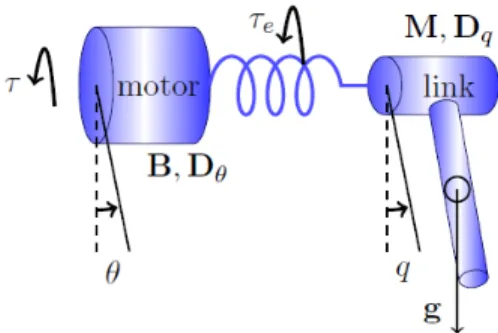
Fig. 4 Serial elastic actuator
Variable stiffness actuators (VSA) are based on a control paradigm where the deformable part of a mechanism is desired or controlled [63, 18]. This deformable part is generally introduced through a spring (Figure 4) which is absorbing undesired forces, and stores/releases energy at the right time. When the spring parameters are fixed the actuator is called a Serial-Elastic Actuator (SEA). The COMAN robot from IIT is built on this principle [65]. It can absorb external impacts. The problem lies in the structure resonance and the stiffness which must be adapted to various phases such as walking/manipulation. Recent mechanisms (CompAct-VSA) have been proposed to modify the actuator stiffness such that the impedance varies along a motion, which is particularly useful for explosive motions such as hammering a
nail. Stiffness is low at the start of the motion, and it is strong at the impact to maximize the force transmitted from the hammer to the nail. An equivalent principle is used on a robot, but in a reverse way, where using a passive toe-joint, the robot stores energy at landing and reuses it for taking off and performing hopping [28]. In general, in addition to the SEA, there are two classes of VSA: the antagonistic VSA (Figure 5), and VSA with a serial spring (Figure 6). For the SEA, the actuator dynamics can be written as follows:
M ¨q+ C(q, ˙q) ˙q + Dqq˙+ τe(φ ) + g(q) = τext B ¨θ+ Dθθ − τ˙ e(φ ) = τ
(6)
where φ = q − θ , B and M are respectively the inertia matrices of the robot bodies and motors, q and θ are the motor angular positions and the body general coordi-nates, Dqand Dθ are respectively the damping of the motor and the body, C(q, ˙q) ˙q are the Centrifugal and Coriolis terms, τeand τextare respectively the torque on the spring and the torque on the actuator while τ is the motor torque. In the case of the
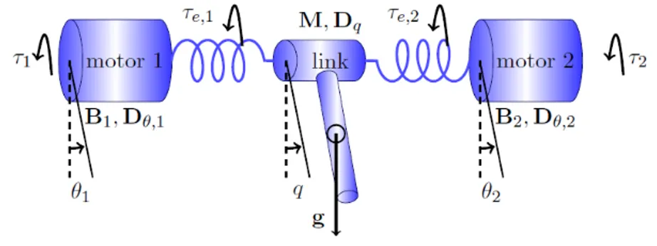
Fig. 5 Antagonist actuator
Antagonist VSA, the actuator dynamics is written in the following manner: M ¨q+ C(q, ˙q) ˙q + Dqq+ =˙
(τe,1(φ1) + τe,2(φ2)) + g(q) = τext B1θ¨1+ Dθ ,1θ˙1− τe,1(φ ) = τ1 B2θ¨2+ Dθ ,2θ˙2− τe,2(φ ) = τ2
(7)
where φ1= q − θ1, φ2= q − θ2, θiis the motor angular position i , τe,iis the torque on spring i and τiis the torque of motor i . Finally, it exists a certain number of actu-ators which have a specific motor to modify the stiffness. This is particularly useful for solving integration problems. Such actuators are called serial variable impedance actuators. However instead of having a simple relationship between two motors act-ing on the same body, we need to consider the followact-ing non linear relationship:
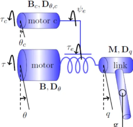
Fig. 6 Variable Stiffness Actuator
M ¨q+ C(q, ˙q) ˙q + Dqq˙+ τe(θc, φ) + g(q) = τext B ¨θ+ Dθθ − τ˙ e(θc, φ) = τ Bcθ¨c+ Dθ ,cθ˙c− ψe(θc, φ) = τc
(8)
where φ= q − θ , Bcand Dθ ,care respectively the auxiliary motor inertia and the the auxiliary motor damping and ψeis the torque applied to the mechanism which mod-ifies the spring stiffness. Several humanoid robots have been designed with tendons which can be considered as SEA (robots Ecce [42], Kotaro [45]), with an antagonist [23], or a serial variable impedance actuator (robot Kenshiro [45]).
For robots with variable stiffness, two points need to be tackled: how to find the desired stiffness ? and how to control this stiffness ? The stiffness at a point on a structure is usually defined mathematically as the ratio between the force and the deflection at the point considered. For actuators with variable stiffness, it is defined as:
κ=∂ τ
∂ q (9)
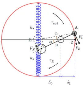
However, the stiffness is not a quantity which can directly measurable, and which must be computed through an observer. The observation quality depends on the knowledge of a certain number of physical parameters which can be difficult to ob-tain from a robot provider. This may imply complex identification processes which do not always provide a sufficient precision. For this reason, numerous approaches try to create approximations or probabilistic representations of this quantity. The Figure 7 illustrates the VSA developed by the IIT for the humanoid robot COMAN. It has a motor changing the stiffness of the actuator by changing the position of the pivot P around which a motion is realized. External load applied at point A is creat-ing a torque τext which is moving the axis by an angle φ . The springs (blue spirals) of stiffness ksgenerates a force along their axis, perpendicular to PB. The projection of this force along the axis PO is compensated by the constraint which prohibits any
Fig. 7 The actuator called CompactVSA
motion of P. The orthogonal projection FSis applied at Γ and is expressed in the following manner:
Fs= 2ksPOsinφ cosφ (10) The term sinφ corresponds to the spring deflection and cosφ to its projection on the axis(PO). Due to the lever mechanism, a force F0
Eis applied on(A) such that :
FE0 = Fs PΓ
AP (11)
By making a series of derivations and simplifying assumptions described in details in [64], it is possible to obtain the following dynamical model:
Iq¨+ N ˙q + τE = τext B1θ¨1+ φ1θ˙1− τE= u1 B2θ¨2+ φ2θ˙2+ τR= u2
(12)
with I the segment inertia, N the Centrifugal and Coriolis effects, B1 and B2the two matrices inertia matrices, φ1and φ2the Centrifugal and Coriolis effects on the motors. u1and u2the motor torques. τe, the elastic torque, is given by :
τe=
2ksδ12∆2θs (∆ − δ1)2
(13)
τR=
2ksn2θ2θs2∆3 (∆ − nθ2)3
(14)
The elastic torque is the torque applied by the spring which is opposed the torque load. The resisting torque to motor M2is the torque resulting from the pivot point displacement. Thus, there is a non linear coupling between the two motors through the variables τ1 and θs. This actuator can be controlled by using a LQR scheme [53]. VSA are generally bulky due to the varying stiffness mechanism. Here, the stiffness variation is obtained thanks to the modification of the pivot P. Contrary to other structures, this one is energetically more efficient [7]. However from the energy transmitted to the system, a part is dissipated. Indeed, the projection of force FS orthogonal to the springs does not deform them but apply a constraint on the actuator mechanism. Having small springs does not allow a strong deflection and limit practically the stiffness variation. This limitation is compensated by the non linearity introduced by the pivot position modification which leads to the following expression of the stiffness:
κ= 2ksδ 2 0∆2 (∆ − δ0)2
(15)
Here the stiffness variation depends only on the distance between the spring and the pivot point δ0. Figure 8 represents the stiffness range that can be reached by the system when δ0is increased with respect to ∆ and for the actuator described in [64].
0 0.5 1 0 1,000 2,000 3,000 4,000 δ0 κ (N m / rad )
Fig. 8 Stiffness of the CompactVSA actuator with ∆= δ0+ δ1= 1, ks= 1. The values are here
4 Sensors
4.1 Encoders
Encoders are an essential part to evaluate the current robot state. A very good pre-cision is necessary, specifically for the legs, in order to prevent impact during foot landing. With an electric actuator, the encoder is generally incremental and is fixed on the motor schaft. Theoretically this enables high precision of the joint displace-ment thanks to the reduction ratio. Typically the theoretical articular precision of a robot such as HRP-2 is in the order of 1/1000 of degrees. The position of the body to which the joint is connected is computed according to the relationship between the encoder and the motor. Errors are introduced by the elasticity of the Harmonic Drive, the body flexibility and the mechanical backlash. More and more robots, such as REEM-C, ARMAR or iCub, now have a direct reading of the articular position. This permits to measure the deflection due to the actuation. Having both position before and after the actuation provides damage detection without going through a verification procedure. However, on the joint side, the encoder has to be of sufficient precision to read the values. This is important as the compliance of the actuator be-tween the encoder on the motor side and the encoder on the joint side may enter in resonance leading to unstable oscillations. For this reason, the LOLA robot having the encoders on both side implements two types of control [41].
4.2 Force torque sensors
In order to maintain balance, it is very important to measure interaction forces with the environment. For this reason, humanoid robots have 6 axis force sensors below the ankles and the wrists. Using force sensors it is possible to compute the position pof the CoP in the following way:
p=∑i=l,rpifi,z ∑i=l,rfi,z
with pi the position of the vertical force sensor at the ankle i (left or right). This measurement is noted fi,z. The difficulty to integrate the sensors is the trade off between the precision and the robustness to impacts during the flying foot landing. The HRP-2 robot uses forces protected by bush rubbers. The robot H7, has gauges put at 8 support points in order to reconstruct the full external wrench [49]. The HUBO robot uses gauges put as a Maltese Cross to provide force measurements along three axis. The robot HRP-2 from DHRC [25] was equipped with a matrix of pressure of size 32 × 32, with each pressure sensor of dimension 4.2 mm × 7 mm under the feet. The measurements are realized at a frequency of 1 KHz. Each sensor can measure a vertical force between 0 and 20 N. The matrix can cover completely
the foot of size 135 mm × 228 mm. Thanks to carbon composites, its thickness is not above 6 mm. This matrix is also able to localize more precisely the contact points with the environment and to adapt the foot pose. However the sensor submitted to strong forces (typically 600 to 900 N) does not resist longer than few weeks. Therefore the most common configuration is to have force sensors between the ankle and the foot soil. For instance, a sensor commercially available is the KMSi from the company IPR.
4.3 Joint level torque sensors
Torque sensors measure torque applied to a joint at the output of the actuator. The goal is to implement a control law using inverse dynamics from the robot model. Several formulations exist, the most known is the Operational Space Inverse Dy-namics proposed by Sentis and al. [57]. This architecture enable to implement be-haviors where the robot is compliant against external contacts. This is a very impor-tant property for human-robot interaction. From a practical viewpoint, this means putting a torque sensor at each joint. This can be costly for humanoid robots (typ-ically 26 sensors for a robot with 6 DoFs at each legs and 7 DoFs at each arm). Another solution to make the robot compliant is to add 6-axis force sensors at the hips and at the shoulders. In conjunction with a skin (cf. paragraph 4.5) this provides the contact position, while the 6-axis force sensor provides the wrench resulting from the force applied to the limbs. In case of multi-contacts, not all the amplitudes of the applied forces can be reconstructed, but this is an interesting trade-off for human-robot interaction.
4.4 Accelerometers and gyrometers
In general a humanoid robot has at least one Inertial Measurement Unit (IMU) which consists in an accelerometer and a gyrometer. This IMU can be localized in the chest or the trunk. Together with a Kalman Filter it gives the orientation of the robot with respect to the gravity field. However without additional information, the orientation of the robot around the vertical axis can not be found. If this informa-tion is not very important for walking on flat floor, it is however very important on uneven terrain. A magnometer could provide sufficient information to recover the yaw but electric actuators are generating electromagnetic fields which are perturbat-ing the measurement. Moreoever magnometers do not work very nicely in buildperturbat-ings due to their low resolution and numerous perturbations. The most common solution is to fuse inertial information with vision.
4.5 Artificial skins
It exists several prototypes of artificial skins covering humanoid robots [2],[14],[10]. They exploit various physical modalities but the most commonly found are forces and pressure provided by capacitive touch sensors and piezo-electric. They are usu-ally used to detect conductive materials such as human skin for human robot inter-action. But, with piezo-electric sensor, it is also possible to add a cover which is transmitting current and then act as a force sensor. The goal is then to localize and estimate the forces applied on certain spots of the robot to achieve whole body ma-nipulation. One of the best example is the control of the iCub robot interacting with humans while performing a Tai-Chi position [52, 50]. A light emitter coupled with a receptor can be used to detect approaching objects. This can be used to prevent col-lision [14]. Using Micro-Electro-Mechanical Systems (MEMS) gives the possibil-ity to measure force orientation, shear forces, vibrations and their duration. Finally adding thermal sensors provides temperature. One of the major blocking point with skin is the necessity to have efficient communication buses due to the large number of sensors needed to cover the surface of the robot. The most advanced techniques are event driven and thus send information only when a contact is detected. There is also a mechanical aspect to this integration, as the cable needed for the commu-nication buses need to be taken into account. A possible solution is to have the skin integrating directly the communication bus which simplifies the problem [6].
4.6 Vision - Lidar
Vision and by extension Lidar provide exteroceptive information, i.e. a represen-tation of the world [15]. In the context of humanoid robotics, it is crucial to plan foot steps in unknown environments. Indeed, detecting potential contact points is necessary for model predictive control often used to make humanoid robot walk. Stereoscopic systems are relatively precises at one meter, which correspond to ma-nipulation applications, but pure triangulation gives an error that is proportional to the square of the distance from this object. By using Simultaneous Localization and Map building (SLAM), it is possible to build more precise maps [16]. A Bayesian formulation provides the integration of various measures related together by models in an uniform mathematical background [24]. A common problem with pure vision is the lack of texture in human made environment. This is mostly important for making the link between interest points in different images. RGB-D cameras pro-jecting a structured light in the infra-red wavelength are an excellent way of fixing this problem and are therefore very popular. When it is possible to embed a graph-ical processing unit (GPU) it is possible to obtain locally dense maps in real time [47]. Outdoor it is more difficult to use RGB-D because the sun disturbs infra-red readings. It is also possible to use LIDAR or time-of-flight-cameras. But they are often big and are therefore difficult to embed in a humanoid robot. For this reason, the Hokuyo laser [43] is the one most found in humanoid robot perception system.
But the time taken to acquire one line is typically 25ms. For this reason, an inter-esting technique is to use learning to find traversable zones. The visual description of such area is learned by coupling the images and the scan reading while stopping the robot. When the robot is in motion it uses the visual information to classify the traversable areas [43].
4.7 Audition
Using microphones is clearly needed during human robot interaction. Localization mechanisms and sources separation have been developed to recognize various lo-cutors speaking at the same time with a robot [22] even when it is moving. The problem is complex due to the reverberation of the sounds in the environment, the shape of the robot head, and the noise created by multiple constituants (fans, motors, gears [61]). The goal is to localize the sources and separate them from each others, take into account the impact of the head on the signal propagation and to model the noise from the robot. Current approaches rely on a probabilistic formulation which are computationally involved. Using array of microphones can improve the recog-nition precision and quality at the cost of increased computational time. A major issue is to develop localization methods providing precise localization in real-time [44]. There already exists methods based on microphones pairs [4] and ones mix-ing computer vision and audition [12, 20]. Implementations for the NAO robots are available as free softwares [12, 20].
Conclusion
In this chapter, various technologies used in humanoid robots have been described. In the last decade several technological breakthroughs resulted in impressive robots such as ATLAS and S-One. The fact that Google bought them in late 2013, to finally sold them to Softbank Robotics in 2017 shows the potential and the limits of such robotics platform. They are now at a level where they can achieve practical task, but the existence of a viable economic application is still an open question. Besides, we can note that TORO, REEM-C or TALOS have been designed in less than 2 years, where most of the first teams in humanoid robotics took much more years to reach the same level. This gives an idea of the progresses achieved in the field recently. The reader will find in the annex a table synthesizing the characteristics of the most relevant humanoid robots in the past years. For high performance humanoid robots which are not designed to interact with humans, a very rigid structure with powerful motors, an IMU and force sensors in the feet are advised. In the case of a humanoid robot aiming at interacting with people, having compliance increases the inherent mechanical safety. It is however coming at the price of a more complex control and
of resonance modes specific to the robot which need to be taken into account in the mechanical design.
o v ervie w of humanoid robots technologies 25
DoFs per limb ware computer nication
Bus sors iCub (IIT, Italy) 23 Kg 0.9 m 53 ( 6xlegs, 7xarms, 3xhip, 3xeyes, 3xneck, 9xhands) BLDC YARP Remote PC104-CAN 9 dofs with cable per hands
Biped Flat feet ankles and hips (2), wrist and shoulders (2), 6D Joint and motor sides Possi-ble 3 dofs for each eye HRP2 (Kawada, Japan) 58 Kg 1.539 m 30 ( 6xlegs, 6xarms, 2xhip, 2xhands) DC Open-RTM Intel Pen-tium M 2.8 GHz PCI 1 par-allel DoF per hand
Biped Flat feet Ankles (2), Wrists (2) 6D
Motor side NA Kinect
+ Point grey stereo camera HRP3 (Kawada, Japan) 68 Kg 1.606 m 68 ( 6xlegs, 7xarms, 2xhip, 6xhands) BLDC Open-RTM Intel Pen-tium M 2.8 GHz PC104-CAN 6 dofs per hands
Biped Flat feet Ankles (2), Wrists (2) 6D
Motor side NA CMOS
camera HRP4 (Kawada, Japan) 39 Kg 1.51 m 34 ( 6xlegs, 7xarms, 6xhip, 2xhead, 2xhands ) BLDC Open-RTM Intel Pen-tium M 1.6 GHz PC104-CAN 2 dofs per hands
Biped Flat feet Ankles (2), Wrists (2) 6D
Motor side NA CMOS
camera HRP4C (Kawada, Japan) 43 Kg 1.58 m 42 (6xlegs, 6xarms, 3xhip, 3xneck, 8xhead, 2xhands) NA Open-RTM Intel Pen-tium M 1.6 GHz PC104-CAN 2 dofs per hands
Biped Flat feet with toe-joint
Ankles (2) 6D
Motor side NA CMOS
camera HUBO-2 (KAIST, Korea) 56 Kg 1.25 m 41 (6xlegs, 5xhands, 3xneck, 6xarms, 6xlegs) DC NA NA CAN 5 dofs per Hands
Biped Flat feet Ankles (2) 3D
O. Stasse 1 and T . Flayols 1
ware computer sors Vision
LOLA (TUM, Germany) 60,88 Kg 1.8 m 25 (2xback, 3xhip, 2xshoulder, 1xel-bow, 1xknee, 2xankles, 1xfinger BLDC NA Intel Core 2 Duo Mobile processor (T7600, 2.33 GHz) CAN-open/ SER-COS III
0 dofs Biped Passive ab-sorbers, active toe-joint Ankles (2) 6D Motor and Joint side NA Two cam-eras Walkman (ITT, Italy) 132 Kg 1.915 m 69 (6xlegs, 7xarms, 3xwaist, 19xhands, 2xhead)
BLDC YARP i7 quad core x2
EtherCat 19 dofs Biped Flat feet Customized
6D force sensors Motor and joint side NA MultiSense 7 + Hokuyo Poppy (INRIA, France) 3.5 Kg 0.84 m 25 (2xneck, 5xlegs, 4xarms, 5xback) Servo motor Dy-namixel Socket/ HTTP access
Arduino NA 0 dofs Biped Passive
toe-joint
2 x 8 force sensors
Encoder in-side the ser-vomotor NA 2 cameras REEM-C (Pal Robotics, Spain) 80 Kg 1.65 m 44 (6xlegs, 7xarms, 7xhand, 2xtorso, 2xhead) BLDC ROS/ Orocos Intel Core i7-2710QE [email protected] GHz CAN 7 dofs (4 pas-sive) per hand
Biped Flat feet Ankles (2) 6D Joint and Motor side NA Stereo Cam-era, camera in the back, Laser TALOS (Pal Robotics, Spain) 95 Kg 1.75 m 34 (6xlegs, 7xarms, 2xtorso, 2xhead, 2xhands) BLDC ROS/ Orocos Intel Core i7 [email protected] Ghz EtherCat 2 dofs per hands
Biped Flat feet Ankles(2), Wrist(2), Torque sensors (26) Joint and Motor side NA Orbec RGB-D ATLAS (Boston Dynamics, USA) 150 kg 1.8 m 30 (6xlegs, 6xarms, 3xback, 3xneck) Hydrau-lic ROS/ Orocos NA NA Several hands can be mounted
Biped Flat feet Plat Ankles (2), Force sensors in the body NA NA Stereo Cam-era, Laser, Cameras in the hands Escher (ROMELA, USA)
77.5 Kg 1.75 m (6xlegs, 7xarms, ) SEA ROS /Briffs
i7/4 cores/3.2 Ghz/2.4 Ghz
CAN 4 DoFs Biped Flat
Feet
Ankles
(2) 6D
ATI-Mini 58
Joint side No MultiSense S7, Hokuyo UTM-30LX-EW Tableau 2 This table describes the most relevant humanoid robots in the recent years. When data are available, it gives a glimpse of the characteristics described
in this paper: robot name, builder, weight, number of degrees of freedom, actuator types, embedded computers, middleware, communication bus, kinematic structure, foot type, ankles, the proprioceptives and exteroceptives sensors are given. This non-exhaustive list gives however a rather large view of the various technologies given in the humanoid robotics field.
References
1. S. Alfayad, F. Ben Ouezdou, and F. Namoun et G. Cheng. High performance integrated electro-hydraulic actuator for hydraulics - part i: Principle, prototypel design and first ex-periments. Sensors and Actuators A: Physical, 169:115–123, 2011.
2. H. Alirezaei and A. Nagakubo et Y. Kuniyoshi. A highly stretchable tactile distribution sensor for smooth surfaced humanoids. In IEEE/RAS Int. Conf. on Humanoid Robotics (ICHR), 2007. 3. N. Ando, S. Kurihara, G. Biggs, and T. Sakamoto et H. Nakamoto. Software deploy-ment infrastructure for component based rt-systems. Journal of Robotics and Mechatronics, 23(13):350–359, 2011.
4. S. Argentieri, A.Portello, M. Bernard, P. Dan´es, and B. Gas. The Technology of Binaural Listening, chapter Binaural Systems in Robotics. Springer, 2013.
5. J. Butterfass, M. Grebenstein, and H. Liu et G. Hirzinger. Dlr-hand ii: next generation of a dextrous robot hand. In IEEE/RAS Int. Conf. on Robotics and Automation (ICRA), 2001. 6. G. Cannata, M. Maggiali, G. Metta, and G. Sandini. An embedded artificial skin for humanoid
robots. In IEEE/RSJ Int. Conf. on Intelligent Robotic Systems (IROS), pages 434–438, 2008. 7. R. Carloni, L. C. Visser, and S. Stramigioli. Variable stiffness actuators: A port-based
power-flow analysis. IEEE Transactions on Robotics, 28(1):1–11, 2012.
8. Justin Carpentier, Steve Tonneau, Maximilien Naveau, Olivier Stasse, and Nicolas Mansard. A versatile and efficient pattern generator for generalized legged locomotion. In IEEE/RAS Int. Conf. on Robotics and Automation (ICRA), pages 3555–3561, 2016.
9. G. Cheng, J. Moritomo S. Hyon, A. Ude, J. Hale, G. Colvin, and W. Scroggin et S. Jacob-sen. Cb: A humanoid research platform for exploring neuroscience. Advanced Robotics, 21(110):1097–1114, 2007.
10. R. Dahiya, G. Metta, and M. Valle et G. Sandini. Tactile sensing-from humans to humanoids. IEEE Transactions on Robotics, 26(11):1–20, 2010.
11. DARPA. The darpa robotics challenge.
12. A. Deleforge and R. Horaud. The cocktail party robot: Sound source separation and localisa-tion with an active binaural head. In ACM/IEEE Internalocalisa-tional Conference on Human-Robot Interaction (HRI), pages 431–438, 2012.
13. J. Englsberger, A. Werner, C. Ott, B. Henze, M. A. Roa, G. Garofalo, R. Burger, A. Beyer, O. Eiberger, K. Schmid, and A. Albu-Schffer. Overview of the torque-controlled humanoid robot toro. In IEEE/RAS Int. Conf. on Humanoid Robotics (ICHR), 2014.
14. P. Mittendorfer et G. Cheng. Integrating discrete force cells into multi-modal artificial skin. In IEEE/RAS Int. Conf. on Humanoid Robotics (ICHR), 2012.
15. Maurice F Fallon, Pat Marion, Robin Deits, Thomas Whelan, Matthew Antone, John McDon-ald, and Russ Tedrake. Continuous humanoid locomotion over uneven terrain using stereo fusion. In IEEE/RAS Int. Conf. on Humanoid Robotics (ICHR), pages 881–888, 2015. 16. D. Filliat. Cartographie et localisation simultanes en robotique mobile. In Techniques de
l’ingnieur. 2014. ref. S7785.
17. P. Fitzpatrick and G. Metta et L. Natale. Towards long-lived robot genes. Robotics and Autonomous Systems, 56(11):29–45, 2008.
18. F. Flacco. Modeling and Control of Robots with Compliant Actuation. PhD thesis, Universi´a di Roma, Dipartimento di Ingegneria Informatica, 2012.
19. P. Garrec. Design of an anthropomorphic upper limb exoskeleton actuated by ball screws and cables. University Polytechnique of Bucarest Science Bulletin, 72(12):23–34, 2010. 20. R. Horaud. Humavips project: Humanoids with auditory and visual abilities in populated
spaces.
21. M. Inaba and S. Kagami et K. Nishiwaki. Robot Anatomy. Iwanami Shoten, 309 pages, 2005. 22. G. Ince, K. Nakadai, T. Rodemann, H. Tsujino, and J. Imura. Multi-talker speech recognition under ego-motion noise using missing feature theory. In IEEE/RSJ Int. Conf. on Intelligent Robotic Systems (IROS), 2010.
23. M. Jaentsch, S. Wittmeier, K. Dalamagkidis, A. Panos, and F. Volkart et A. Knoll. Anthrob - a printed anthropomimetic robot. In IEEE/RAS Int. Conf. on Humanoid Robotics (ICHR), 2013.
24. M. Kaess, H. Johannsson, R. Roberts, V. Ila, and J. Leonard et F. Dellaert. Isam2: Incremental smoothing and mapping using the bayes tree. Int. Journal of Robotics Research, 31(12), 2012. 25. S. Kagami, K. Nishiwaki, J. Kuffner, S. Thompson, J. Chestnutt, and M. Stilman. et P. Michel. Humanoid HRP2-DHRC for Autonomous and Interactive Behavior, pages 103–117. Springer-Verlag, 2007.
26. S. Kajita, F. Asano, M. Morisawa, K. Miura, K. Kaneko, and F. Kanehiro et K. Yokoi. Ver-tical vibration suppression for a position controlled biped robot. In IEEE/RAS Int. Conf. on Robotics and Automation (ICRA), 2013.
27. S. Kajita, K. Kaneko, M. Morisawa, and S. Nakaoka et H. Hirukawa. Zmp-based biped run-ning enhanced by toe springs. In IEEE/RAS Int. Conf. on Robotics and Automation (ICRA), 2007.
28. S. Kajita, T. Nagasaki, K. Kaneko, and K. Yokoi et K. Tanie. A running controller of humanoid biped hrp-2lr. In IEEE/RAS Int. Conf. on Robotics and Automation (ICRA), 2005.
29. H. Kaminaga, K. Odanaka, Y. Ando, and S. Otsuki et Y. Nakamura. Evaluations on contribu-tion of backdrivability and force measurement performance on force sensitivity of actuators. In IEEE/RSJ Int. Conf. on Intelligent Robotic Systems (IROS), 2013.
30. K. Kaneko and K. Harada et F. Kanehiro. Development of a multi-fingered hand for life-size humanoid robots. In IEEE/RAS Int. Conf. on Robotics and Automation (ICRA), 2007. 31. K. Kaneko, K. Harada, F. Kanehiro, and G. Miyamori et K. Akachi. Humanoid robot hrp-3.
In IEEE/RSJ Int. Conf. on Intelligent Robotic Systems (IROS), 2008.
32. K. Kaneko, F. Kanehiro, M. Morisawa, K. Akachi, G. Miyamori, and A. Hayashi et N. Kane-hira. Humanoid robot hrp-4 - humanoid robotics platform with lightweight and slim body -. In IEEE/RSJ Int. Conf. on Intelligent Robotic Systems (IROS), 2011.
33. K. Kaneko, F. Kanehiro, M. Morisawa, T. Tsuji, K. Miura, S. Nakaoka, and S. Kajita et K. Yokoi. Hardware improvement of cybernetic human hrp-4c for entertainment use. In IEEE/RSJ Int. Conf. on Intelligent Robotic Systems (IROS), 2011.
34. K. Kaneko, M. Morisawa, S. Kajita, S. Nakaoka, T. Sakaguchi, R. Cisneros, and F. Kane-hiro. Humanoid robot hrp-2 kai - improvement of hrp-2 towards disaster response tasks. In IEEE/RAS Int. Conf. on Humanoid Robotics (ICHR), pages 132–139, 2015.
35. A. Kargov, T. Asfour, C. Pylatiuk, R. Oberle, H. Klosek, S. Schulz, K. Regenstein, and G. Bret-thauer et R. Dillmann. Development of an anthropomorphic hand for a mobile assistive robot. In Int. Conf. on Rehabilitation Robotics: Frontiers of the Human-Machine Interface, 2005. 36. Sisir Karumanchi, Kyle Edelberg, Ian Baldwin, Jeremy Nash, Jason Reid, Charles Bergh, John
Leichty, Kalind Carpentier, Matthew Shekels, Matthew Gildner, David Newill-Smith, Jason Carlton, John Koehler, Tatyana Dobreva, Matthew Frost, Paul Hebert, James Borders, Jeremy Ma, Bertrand Douillard, Paul Backes, Brett Kennedy, Brian Satzinger, Chelsea Lau, Katie Byl, Krishna Shankar, and Joel Burdick. Team robosimian: Semi-autonomous mobile manipulation at the 2015 darpa robotics challenge finals. Journal of Field Robotics, 34(2):305–332, 2017. 37. J. Koenemann, A. Del Prete, Y. Tassa, E. Todorov, O. Stasse, M. Bennewitz, and N. Mansard.
Whole-body model-predictive control applied to the HRP-2 humanoid. In IEEE/RSJ Int. Conf. on Intelligent Robotic Systems (IROS), pages 3346–3351, 2015.
38. T. Kozuki, Y. Motegi, T. Shirai, Y. Asano, J. Urata, Y. Nakanishi, and K. Okada et M. Inaba. Design of upper limb by adhesion of muscles and bones - detail human mimetic muscoloskele-tal humanoid kenshiro -. In IEEE/RSJ Int. Conf. on Intelligent Robotic Systems (IROS), 2013. 39. M. Lapeyre and P. Rouanet et P.-Y. Oudeyer. Poppy humanoid platform: Experimental evalu-ation of the role of a bio-inspired thigh shape. In IEEE/RAS Int. Conf. on Humanoid Robotics (ICHR), 2013.
40. Jeongsoo Lim, Inho Lee, Inwook Shim, Hyobin Jung, Hyun Min Joe, Hyoin Bae, Okkee Sim, Jaesung Oh, Taejin Jung, Seunghak Shin, Kyungdon Joo, Mingeuk Kim, Kangkyu Lee, Yunsu Bok, Dong-Geol Choi, Buyoun Cho, Sungwoo Kim, Jungwoo Heo, Inhyeok Kim, Jungho Lee, In So Kwon, and Jun-Ho Oh. Robot system of drc-hubo+ and control strategy of team kaist in darpa robotics challenge finals. Journal of Field Robotics, 34(4):802–829, 2017. 41. Lohmeier. Design and Realization of a Humanoid Robot for Fast and Autonomous Bipedal
42. C. Schmaler M. Jaentsch, S. Wittmeier, and K. Dalamagkidis et A. Knoll. A scalable joint-space controller for musculoskeletal robots with spherical joints. In ROBIO, 2011.
43. D. Maier and C. Stachniss et M. Bennewitz. Vision-based humanoid navigation using self-supervised obstacle detection. Int. Journal of Humanoid Robotics, 10(12), 2013.
44. K. Nakamura, R. Gomez, and K. Nakadai. Real-time super-resolution three-dimensional sound source localization for robots. In IEEE/RSJ Int. Conf. on Intelligent Robotic Systems (IROS), pages 3949–3954, 2013.
45. Y. Nakanishi, S. Ohta, T. Shirai, Y. Asano, T. Kozuki, Y. Kakehashi, H. Mizoguchi, T. Kuro-tobi, Y. Motegi, K. Sasabuchi, J. Urata, K. Okada, and I. Mizuuchi et M. Inaba. Design ap-proach of biologically-inspired musculoskeletal humanoids. Int. Journal of Advanced Robotic Systems, 2013.
46. S. Nakaoka, S. Hattori, F. Kanehiro, and S. Kajita et H. Hirukawa. Constraint-based dynamics simulator for humanoid robots with shock absorbing mechanisms. In IEEE/RSJ Int. Conf. on Intelligent Robotic Systems (IROS), 2007.
47. R. Newcombe, S. Izadi, O. Hilliges, D. Molyneaux, D. Kim, A. Davison, P. Kohli, J. Shotton, and S. Hodges et A. Fitzgibbon. Kinectfusion: Real-time dense surface mapping and tracking. In ISMAR, 2011.
48. R. Niiyama and A. Nagakubo et Y. Kuniyoshi. Mowgli: A bipedal jumping and landing robot with an artificial musculoskeletal system. In IEEE/RAS Int. Conf. on Robotics and Automation (ICRA), 2007.
49. K. Nishiwaki, Y. Murakami, S. Kagami, Y. Kuniyoshi, and M. Inaba et H. Inoue. A six-axis force sensor with parallel support mechanism to measure the ground reaction force of humanoid robot. In IEEE/RAS Int. Conf. on Robotics and Automation (ICRA), 2002. 50. Francesco Nori, Silvio Traversaro, Jorhabib Eljaik, Francesco Romano, Andrea Del Prete,
and Daniele Pucci. icub whole-body control through force regulation on rigid non-coplanar contacts. Frontiers in Robotics and AI, 2:6, 2015.
51. C. Ott and M. Roa et G. Hirzinger. Posture and balance control for biped robots based on contact force optimization. In IEEE/RAS Int. Conf. on Humanoid Robotics (ICHR), 2011. 52. D. Pucci. icub performing highly dynamic tai chi while interacting with humans, 2016. 53. I. Sardellitti, G. Medrano-Cedra, N. Tsagarakis, and A. Jafari et D. Caldwell. Gain scheduling
control for a class of variable stiffness actuators based on lever mechanisms. itro, 29(13):791– 798, 2013.
54. J. Saunders and V. Inman et H. Eberhart. The major determinants in normal and pathological gait. Journal of Bone Joint Surgery, A(135):543–558, 1953.
55. Alexander Schmitz, Ugo Pattacini, Francesco Nori, Lorenzo Natale, Giorgio Metta, and Giulio Sandini. Design, realization and sensorization of the dexterous icub hand. In IEEE/RAS Int. Conf. on Humanoid Robotics (ICHR), pages 186–191, 2010.
56. R. Sellaouti, O. Stasse, S. Kajita, and K. Yokoi et A. Kheddar. Faster and smoother walking of humanoid hrp-2 with passive toe joints. In IEEE/RSJ Int. Conf. on Intelligent Robotic Systems (IROS), 2006.
57. L. Sentis and O. Khatib. A whole-body control framework for humanoids operating in human environments. In IEEE/RAS Int. Conf. on Robotics and Automation (ICRA), 2006.
58. Olivier Stasse. Technologies des robots humano¨ıdes. In Applications en robotique. Techniques de l’ingnieur, 2014.
59. Olivier Stasse, Thomas Flayols, Rohan Budhiraja, Kevin Giraud-Esclasse, Justin Carpentier, Andrea Del Prete, Philippe Sou`eres, Nicolas Mansard, Florent Lamiraux, Jean-Paul Laumond, Luca Marchionni, Hilario Tome, and Francesco Ferro. TALOS: A new humanoid research platform targeted for industrial applications. 2017.
60. Anthony Stentz, Herman Herman, Alonzo Kelly, Eric Meyhofer, G. Clark Haynes, David Stager, Brian Zajac, J. Andrew Bagnell, Jordan Brindza, Christopher Dellin, Michael George, Jose Gonzalez-Mora, Sean Hyde, Morgan Jones, Michel Laverne, Maxim Likhachev, Levi Lister, Matt Powers, Oscar Ramos, Justin Ray, David Rice, Justin Scheifflee, Raumi Sidki, Siddhartha Srinivasa, Kyle Strabala, Jean-Philippe Tardif, Jean-Sebastien Valois, J. Michael Vande Weghe, Michael Wagner, and Carl Wellington. Chimp, the cmu highly intelligent mo-bile platform. Journal of Field Robotics, 32(2):209–228, 2015.
61. T. Takahashi, K. Nakadai, K. Komatani, T. Ogata, and H.G. Okuno. Improvement in listening capability for humanoid robot hrp-2. In IEEE/RAS Int. Conf. on Robotics and Automation (ICRA), pages 470–475, 2010.
62. B. Tondu. Modelling of the mackibben artifical muscle: A review. Journal of Intelligent Materials Systems and Structures, 23(13):225–253, 2012.
63. G. Tonietti, R. Schiavi, and A. Bicchi. Design and control of a variable stiffness actuator for safe and fast physical human/robot interaction. In IEEE/RAS Int. Conf. on Robotics and Automation (ICRA), pages 526–531, 2005.
64. N. Tsagarakis and I. Sardellitti et D. Caldwell. A new variable stiffness actuator (compact-vsa): Design and modelling. In IEEE/RSJ Int. Conf. on Intelligent Robotic Systems (IROS), 2011.
65. N. Tsagarakis, S. Morfey, G. Cerda, and Z. Li et D. Caldwell. Compliant humanoid coman: Optimal joint stiffness tuning for modal frequency control. 2013.
66. J. Urata, Y. Nakanishi, and K. Okada et M. Inaba. Design of high torque and high speed leg module for high power humanoid. In IEEE/RSJ Int. Conf. on Intelligent Robotic Systems (IROS), 2010.
67. J. Vermeulen, B. Verrelst, B. Vanderborght, and D. Lefeber et P. Guillaume. Trajectory plan-ning for the walking biped ”lucy”. International Journal of Robotics Research, 25(19):867– 887, 2006.
68. P. M. Wensing, A. Wang, S. Seok, D. Otten, J. Lang, and S. Kim. Proprioceptive actuator design in the mit cheetah: Impact mitigation and high-bandwidth physical interaction for dy-namic legged robots. IEEE Transactions on Robotics, 33(3):509–522, 2017.
![Fig. 2 Non-planar contacts to extend the reachable space (left) [37] and to perform generalized locomotion (right) [8]](https://thumb-eu.123doks.com/thumbv2/123doknet/14247031.487679/7.918.325.576.586.782/planar-contacts-extend-reachable-space-perform-generalized-locomotion.webp)