Publisher’s version / Version de l'éditeur:
MP Materials Performance, 36, August 8, pp. 64-67, 1997-08-01
READ THESE TERMS AND CONDITIONS CAREFULLY BEFORE USING THIS WEBSITE.
https://nrc-publications.canada.ca/eng/copyright
Vous avez des questions? Nous pouvons vous aider. Pour communiquer directement avec un auteur, consultez la première page de la revue dans laquelle son article a été publié afin de trouver ses coordonnées. Si vous n’arrivez pas à les repérer, communiquez avec nous à PublicationsArchive-ArchivesPublications@nrc-cnrc.gc.ca.
Questions? Contact the NRC Publications Archive team at
PublicationsArchive-ArchivesPublications@nrc-cnrc.gc.ca. If you wish to email the authors directly, please see the first page of the publication for their contact information.
NRC Publications Archive
Archives des publications du CNRC
This publication could be one of several versions: author’s original, accepted manuscript or the publisher’s version. / La version de cette publication peut être l’une des suivantes : la version prépublication de l’auteur, la version acceptée du manuscrit ou la version de l’éditeur.
Access and use of this website and the material on it are subject to the Terms and Conditions set forth at
Potential survey technique for prestressed concrete pipes
Brousseau, R. J.; Chagnon, N.; Baldock, B.
https://publications-cnrc.canada.ca/fra/droits
L’accès à ce site Web et l’utilisation de son contenu sont assujettis aux conditions présentées dans le site LISEZ CES CONDITIONS ATTENTIVEMENT AVANT D’UTILISER CE SITE WEB.
NRC Publications Record / Notice d'Archives des publications de CNRC:
https://nrc-publications.canada.ca/eng/view/object/?id=666b3eb0-cf47-4c88-bfee-132e5e54a1c8 https://publications-cnrc.canada.ca/fra/voir/objet/?id=666b3eb0-cf47-4c88-bfee-132e5e54a1c8http://www.nrc-cnrc.gc.ca/irc
Pot e nt ia l surve y t e c hnique for pre st re sse d c onc re t e pipe s
N R C C - 4 0 6 0 1
B r o u s s e a u , R . J . ; C h a g n o n , N . ; B a l d o c k , B .
A u g u s t 1 9 9 7
A version of this document is published in / Une version de ce document se trouve dans:
MP Materials Performance, 36, (8), August, pp. 64-67, August 01, 1997
The material in this document is covered by the provisions of the Copyright Act, by Canadian laws, policies, regulations and international agreements. Such provisions serve to identify the information source and, in specific instances, to prohibit reproduction of materials without written permission. For more information visit http://laws.justice.gc.ca/en/showtdm/cs/C-42
Les renseignements dans ce document sont protégés par la Loi sur le droit d'auteur, par les lois, les politiques et les règlements du Canada et des accords internationaux. Ces dispositions permettent d'identifier la source de l'information et, dans certains cas, d'interdire la copie de documents sans permission écrite. Pour obtenir de plus amples renseignements : http://lois.justice.gc.ca/fr/showtdm/cs/C-42
MATERIALS SELECTION & DESIGN
E E
Potential Survey Technique
for Prestressed Concrete Pipes
Rejean Brousseau, Nathalie Chagnon, and Bruce Baldock
Institute for Research in Construction, National Research Council of Canada, Bldg. M·20, Montreal Rd., Ottawa, Ontario, Canada, K1A OR6
Prestressed concrete pipe sections were corroded by the action of salt and the applica-tion of an anodic current in well-defined areas. A potential survey of the pipes was performed before they were buried on the grounds of the National Research Council of Canada urban infrastructure research site. After they were buried, pipe potentials wete recorded using a reference electrode displaced at regular intervals on the ground surface directly above the pipe. Potentials were also measured using reference elec-trodes permanently embedded in the ground near the pipe. On the basis ofthe test data, a pipe potential survey from the surface of the ground could not be used to locate specific areas damaged by corrosion.
P
restressed concrete pipes are usually durable and little prone to metallic corrosion be-cause of their dense protective con-crete covers. The alkalinity of the concrete cover promotes the forma-tion of a passive oxide film and there-fore prevents corrosion of the steel core and prestressed wires. Although there are very few reported cases, pipe corrosion problems can eventuallyarise in soils heavily contaminated
with chlorides because there can be a migration of the chloride ions through the concrete cover, leading to a break-down of the protective film that nor-mally passivates the steel in the
concrete.1
Corrosion in prestressed concrete pressure pipes has on very rareッ」」。セ sians caused sections to deteriorate
prematurely.' But since the
pre-stressed wires are subjected to stresses
64
equal to70%to75%of their ultimate strength, the failure state can be reached with relatively limited metal corrosion. A20%to30%reduction in
wire diameterbycorrosion can cause
them to break. After a certain num-ber of prestressed wires have bro-ken, the pipe's strength decreases. If the operating pressure is not high enough to break the remaining pre-stressed wires, the pipe may bend, causing further cracks that will cause more wires to break. However, if the water pressure in the pipe exceeds the pipe strength, a catastrophic
fail-ure may occur.3
Determination of a pipe's
condi-tion before failure occurs is therefore
very important. There are at present
a variety of nondestructive
diagnos-tic techniques available, including those based on potential surveys. One of the advantages of potential survey
techniques is that the measurements can be taken from the surface of the ground.
The purpose of this article is to assess the possibility of using poten-tial surveys to locate areas damaged by corrosion. It is well known that unless cathodic protection is applied, the electrochemical potential of steel
in concrete is usually more negative with increasing corrosion activity. On
that basis, it seems possible to locate corroding concrete pipe sections by half-cell potential surveys. Moreover, the potential measuring technique is routinely used to determine the
cor-rosion of reinforced concrete in
bridges and parking garages. It
in-volves using a voltmeter to measure
the potential difference between a copper-copper sulfate (Cu/CuS04) reference electrode and the steel rein-forcing the pipe.
A potential more positive than
-200 mV indicates a probability greater than90%that the reinforcing steel is not corroding.' On the other hand, a potential more negative than
-350mV denotes a probability>90%
that the prestressed wires are corrod-ing. Measurement of the potentials
can therefore indicate the presence or absence of corrosion on the steel
MATERIALS SELECTION & DESIGN
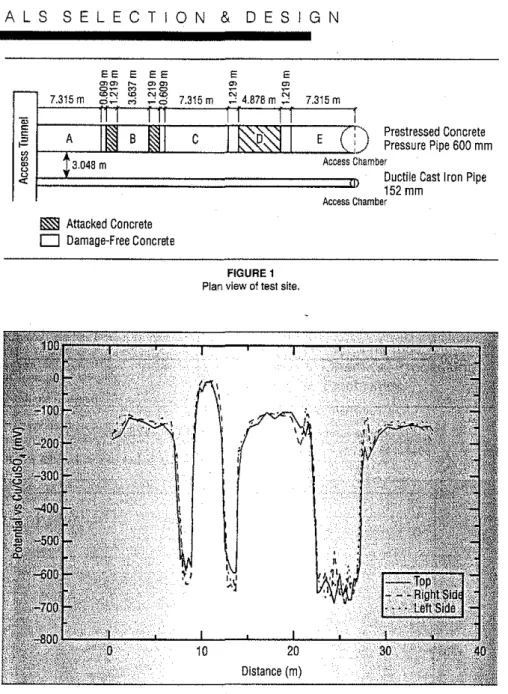
FIGURE 1
Plan view of test site.
)' Prestressed ConcretePressure Pipe 600 mm
hamber
Ductiie Cast Iron Pipe t52mm
Access Chamber
65
Before burying the pipe sections,electrical wire connections were made
to each one. In addition, some20 per-manent Cu/CuS04 reference elec-trodes were buried at90 degrees on either side of the pipe and linked to a monitoring control board. These elec-trodes helped determine the influence of the distance between the reference electrode and the pipe in a potential survey.
Results and Discussion Potentials were measured on
each pipe section before they were buried. Figure 2 shows the potential measurements obtained along the center and sides of the pipe sections.
20 Distance (m) r - 7.315m セn セ "!l.q 7.315m セ 4.878mセ 7.315m 0""': セo
'"
e-
II I I, e A BII
Cセセ
I
E(:
,: セ 13.048m -セ Access C セ u u'"
l§i§ Attacked Concrete
D
Damage-Free ConcreteFIGURE2
Potential of the pipe before it was buried.Potential measurements were recorded at the 9, 12, and 3 o'clock
positions.
shows a diagram illustrating the pipe sections and the precorroded areas.
The pipe sections were buried at a depthof2.13m. Each pipe was sur-rounded by a 19 mm cushion of stone and backfilled with natural soil con-sisting of a mixture of clay and stone. The resistivity of the soil, as measured by means of the 4-pin method, was in the order of3,500ohm-ern. The five sections of prestressed concrete pipe were laid end-to-end and electrically continuous with each other and placed 3 m away from a ductile cast iron pipe. One of the pipe ends was
located in an access tunnel while the
other end was accessible through a manhole.
inforcement. Other phenomena,
how-ever, such as cathodic protection and
stray currents, may give very
nega-tive readings.5-7
In an article published in 1993, Hall' concluded that it was possible to locate corroded areas by means of a potential survey. Other authors, however, believe that it might be dif-ficult to specifically identify the an-odic areas on pipes using potential survey techniques. According to Bianchetti,' a potential survey of pre-stressed concrete pipe along the sur-face of the ground produces coupling of the potentials of the anodic and cathodic sites. He believes that the influence of cathodic sites on anodic areas might reduce and even mask the growth of predictable potentials
in anodic areas.
This field research was con-ducted to better understand these
contradictory views. Hall's results
were obtained in a high resistivity soil using an inert anode located be-tween the covering concrete and the
steel reinforcement to simulate a
cor-rosion cell. In this study, experiments were conducted on precorroded pipe
sections in a lower resistivity soil.
Method
Measurements were taken on
five sections of prestressed concrete
pipe 610 mm in diameter. Two of
these sections were precorroded to
simulate severely deteriorated pipes. Considerable effort was required to perform this task: the concrete cover was destroyed by drilling or sawing until the steel was accessible. Salt was then deposited directly on the ex-posed reinforcing steel for 5 weeks to
accelerate the corrosion process. To
promote greater penetration of salt
into the concrete cover and heavier
corrosion of the steel reinforcement, an anodic current was applied. A tem-porary steel mesh cathode and a tarp were placed on the surface of the con-crete pipe and later used to apply an anodic current of =4.5 A for 5 weeks. Two corroded areas 1.2 m long were thus created on pipe B near its
ex-tremities while a central area of 4.8 m
was produced on pipe D. Figure 1
MATERIALS SELECTION & DESIGN
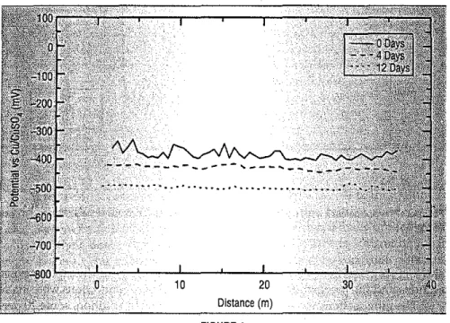
FIGURE4
Potential survey of the prestressed concrete pipes recorded after burial and electrical connection 10 a ductile cast iron pipe. Measurements taken with reference electrode at surface of ground along pipe A to E, at the indicated intervals subsequent to making an electrical contact 10 ductile cast iron pIpe.
FIGURE 3
Potential survey of pipe A to E recorded after they were buried.
10 20
Distance (m)
ing medium. The soil allowed a
gal-vanic corrosion current to pass 「・セ
tween the anodic and cathodic areas. The absence of a potential drop approaching the anodic areas could also have been explained by the fact that the readings taken by the refer-ence electrode covered a cone of= 120 degrees. But as just explained, this was not the case. It might be sug-gested, however, that the potential survey results obtained did not repre-sent potential values of localized ar-eas, but instead an average potential
over one or more entirepipesections.
This was believed to be true in low resistivity soils or in the case where potential measurements were taken at a significant distance from the pipe.
Reference electrodes embedded near the pipe would sense smaller areas because of their proximity to the pipe. However, the potentials
re-corded at corroded areas were
simi-lar to those recorded on noncorroded pipe sections (Figure 3). The electro-chemical interaction of the cathodic
areas withthe anodic areas was
be-lieved to considerably attenuate any potential gradients, thereby making it difficult to localize any corroded sections. The small difference between the results obtained from a reference electrode displaced at the surface of the ground and a reference electrode embedded near the pipe was likely caused by the IR drop soil resistance.
Polarization of the concrete pipes by interaction with ductile cast iron mains pipes was also studied. To
achieve this, an electric connection
was made between the prestressed concrete pipe and the parallel ductile cast iron pipe located 3 m away. The potential surveys performed on the prestressed concrete pipe showed a decrease in the potentials as a result of the connection with the ductile iron pipe (Figure 4). Because the ductile iron pipe in native soil had a poten-tial of -600 mV and the prestressed concrete pipe had an average poten-tial of -380 mV, the cast iron behaved as an anode and negatively polarized
the prestressed concrete water main.
The ductile iron pipe therefore ca-thodically protected the prestressed
40 30
...
" ...,.
Electrode Near Pipes Electrode at Surtace of Ground
ments were taken from the surface of the ground by displacing a reference electrode along the pipe at a regular interval of 60 cm and with reference electrodes embedded near the pipe. Analysis of the results showed that it was difficult to locate the corroded sections. This difficulty might be at-tributed to the fact that the buried pipe was surrounded by a
conduct-20 Distance (m) ',,"':.,... 10
...
".
.
' .' '. ".
... 100 0 -100;;-g
-200 • 0 <.n セ -300 \,1 セ '-' セ -400.,.
""
セ -500 セ;r
-600 -700 -800 0Corroded areas in pipes Band D were clearly evident in these potential pro-files. The areas of sound concrete had a potential of --150 mV, while the corroded areas had a potential in the vicinity of -600 mV with respect to the Cu/CuSO, reference electrode.
Figure 3 presents the potential surveys recorded on pipes A to E af-ter they were buried. The
67
..
HASTELLOY is a trademark01
HAYNES INTERNATIONAL, INC. FERRALIUMis atrademark of MEIGHS. LTD. STELUTE Is a trademark of THERMAOYNE, INC. COMPLETE RANGE OF PRODUCTS INVENTORIED HASTELLOY' ALLOY B-2, 0-276, 0-22. G-30, FERRALIUM' 255, 2001201. CM40D, ANDstellャteセ 68
BAR INVENTORY IN: K-500. BOOH. 600 AND
CARPENTERRdc「Sセ
hNcセ Starck Inc.
45lndustrial"PJace
NeWlon, Ma, 0216'·1951/USA Phone+11ッQWOVSPセUYRP Fax ' KQOVQWOVセoGUYPLセ
H.G. Starck
_ 2 csPowders
for Thermal
Spraying
Spray Powders for
HIgh Performance
Applications
•. Automotive and Diesel • Printing
ilPuip-and Paper
• Land-based steam and gas turbines • Aerospace • Textile • Petrochemical • Chemical Processing· • Electronics
Circle138on Reader Service Card
Circle 139on Reader Service Card
Complete range of pipe and fittings in
alloy 600 to complement the high nickel
alloys already stocked.
Hastelloy alloy B-2, C-276, C-22, G·30,
200/201 and 400
•
セB
CORROSION MATERIALS
1-800·535-8032 Baker, LA 1-800-455-2276 Houston, TX 01-800-401·1734 S. Windsor, CTRejean Brousseau is a corrosion research of-ficer with the National Research Council of Canada. He has a years of experience in the field of corrosion, specialiZing in cathodic protection of concrete, metallized zinc, and diagnostic techniques.
Nathalie Chagnon is a technical officer with the National Research Council of Canada. She has worked therefor three summers on projects involving corrosion in pipes and concrete. Bruce Baldock is a technical officer with the National Research Council of Canada. He has 6 years of laboratory and field experience in corrosion prevention systems, specializing in barrier coatings, and galvanic and impressed current systems.
erations of Corrosion Problems oEPrestressed Con-crete Cylinder Pipe," Corrosion EffectofStrayCur-rents and the Techniques-Symposium Proceedings
11 (1984),p.92.
3.RoL.Bianchetti, MP 32, 8 (1993):p.62.
4. ASTM C 876·91, "Standard Test Method for Half· Cell Potentials of Uncoated Reinforcing Steel in Concrete," Annual Book of ASTM Standards (West Conshohocken, PA: ASTM).
5. M.G. Peris, MP 31, 5 (1992): p. 21.
6, M,G. Perie, M.A, Guillen, MP 34, 1 (1995): p. 25.
7.s,c.Hall,I. Mathew, "Cathodic Protection
Re-quirements of Prestressed Concrete Cylinder Pipe," Proc. 2nd International Conference on Advances in Underground Pipeline Engineering (1995), p. 168. 8. S.c. Hall, "Corrosion Monitoring of Prestressed
Concrete Cylinder Pipe, Conference andeクーッウゥセ
tion on Pipeline Infrastructure," 1993.
concrete pipe when there was electri-cal continuity between the two.
Because of the electrical continu-ity between the prestressed concrete pipe and the ductile iron pipe, the potentials of the reinforcing steel were shifted toward more electronegative values. The coupling of the poten-tials between the two pipes made it impossible to locate the precorroded areas on the prestressed concrete pipe. Such coupling was often ob-servable in urban areas where there was interference of cast iron pipes with concrete pipes.
Therefore, potential measure-ments could not be used to localize corroding areas of prestressed con-crete pipes. However, where poten-tials were more positive than -200 mV vs the Cu/CuSO, reference elec-trode, a prestressed concrete pipe was likely not corroding.
MATERIALS SELECTION & DESIGN
Conclusions
• The potential survey technique is unable to reliably identify corroded
sections of a pipe buried in a」ッョセ
ducting medium like soil.
• The soil allowed a galvanic corro-sion current to pass between an-odic and cathan-odic areas, and this, considerably attenuated the poten-tial gradients located between the two areas.
• The pipes had a tendency to polar-ize and move toward a uniform potential when there was electri-cal continuity between them. • The ductile cast iron pipe acted as
an anode and cathodically pro-tected the prestressed concrete pipe when it was connected electrically to it. This masked any possible de-tection of anodic areas on pre-stressed concrete pipes.
• Potentials more positive than -200 mV vs the Cu/CuSO, reference electrodes indicated pipe sections that had no trace of corrosion problems.
• Prestressed concrete pipes did not easily corrode.
References
1. J.5. Clift, "PCCP-A Perspective on Perfor-mance," Proc. Annual AWWA, Conference, June 1991 (Denver, CO: AWWA),
2. P.S. Rothman, R.E. Price, "Detection and