Configurable Dynamic Privacy for Pervasive Sensor Networks
by
Nan-Wei Gong
Submitted to the Program in Media Arts and Sciences,
School of Architecture and Planning,
in partial fulfillment of the requirements for the degree of
Master of Science in Media Arts and Sciences
at the
MASSACHUSETTS INSTI E
OF TECHNOLOGY
OCT 2
6 2009
LIBRARIES
MASSACHUSETTS INSTITUTE OF TECHNOLOGY
~
2009ARCHIVES
August 2009
@ Massachusetts Institute of Technology 2009. All rights reserved.
Author
Program in Me diaArts and Sciences August 7, 2009
Certified by
Joseph A. Paradiso Associate Professor of Media Arts and Sciences MIT Media Laboratory Thesis Supervisor
Accepted by
Deb Roy Chair, Department Committee on Graduate Students Program in Media Arts and Sciences MIT Media Laboratory
Configurable Dynamic Privacy for Pervasive Sensor Networks
by
Nan-Wei Gong
Submitted to the Program in Media Arts and Sciences, School of Architecture and Planning,
on August 7th, in partial fulfillment of the
requirements for the degree of
Master of Science in Media Arts and Sciences
Abstract
Ubiquitous computing sensor networks have greatly augmented the functionality of interactive media systems by adding the ability to capture and store activity-related information. Analyzing the information recorded from pervasive sensor networks can provide insight about human behavior for better personalized system services, as well as richer media content and social communication. With these increased capabilities, serious concerns which create great obstacles to the deployment of such network are raised with regard to privacy and boundaries. However, there exist no real data currently about privacy in pervasive media networks and most studies that have been made so far are speculative. This thesis presents the design and implementation of a configurable infrastructure that can protect users' dynamic levels of privacy in a pervasive sensor network. Through an active badge system, users have different options to disable each type of data transmission. This work evaluates approaches for privacy protection through conducting an extensive user study in an actual ubiquitous invasive sensing environment to obtain feedback via sensor system data and questionnaires and correlates that information for future reference in the design of privacy-protected ubiquitous sensor networks. Results from the user study indicated that an active badge for on-site control, especially periodically broadcast RF beacon for privacy control, is the most effective and acceptable method. However, it also suggested that if every occupant in the building used this approach to constantly block all data transmission, significant system blinding (on the order of 30 % or more) would be incurred. These results allow a better understanding of what value is assessed to privacy versus capabilities/awareness beyond the current assumptions.
Thesis Supervisor: Joseph A. Paradiso
Title: Associate Professor of Media Arts and Sciences, MIT Media Lab 3
Configurable Dynamic Privacy for Pervasive Sensor Networks
by
Nan-Wei Gong
The following people served as readers for this thesis:
Thesis Reader
Associate Professor of Media Arts Program in Media Arts
_ I "I-leb Roy and Sciences and Sciences I_7 Thesis Reader
Alex (Sandy) Pentland Toshiba Professor of Media Arts and Sciences Program in Media Arts and Sciences
Acknowledgments
I would like to thank Professor Joe Paradiso for giving me the chance to work with him and being the best advisor that anyone could ever hope for. Coming to the Media Lab for my
graduate study was a life-changing decision and I could have never done it without the support from Professors Samuel C.C. Ting and Peter Fisher. Also, I would like to thank my thesis readers, Professors Alex (Sandy) Pentland and Deb Roy for their constructive feedbacks during my thesis writing process.
I would like to thank everyone in the Responsive Environments Group. Without them, I could not have completed this project.
To Mat Laibowitz: for teaching me literally everything I know and providing extermly valuable advice on my projects and life.
To Bo Morgan: for helping with coding and being the best user study subject on this planet. To Mark Feldmeier: for offering his generous help on everyone's electronics project. To Michael Lapinski: for always explaining things in a way that I can understand. To Manas Mittal and Behram Mistree: for making my earliest time in the Media Lab so much more enjoyable.
To Alex Reben: for being a great officemate and slapping my troubles away. To Matt Aldrich: for fixing CargoNet.
To everyone who has participated in my user study: for wearing a blinking gizmo avidly. To Lisa Lieberson: for being always helpful and supportive.
To Pamela Siska: for working with me on my writing.
To Linda Peterson and Aaron Solle: for their support and timely reminders.
I would also like to thank all my friends for their help and support along the way especially To Amit Zoran: for always making things perfect.
To Dori Lin: for being my debugger and always showing up magically when I stumbled. To Cati Vaucelle: for giving me great advice and insight.
To Aithne Pao, Wu-Hsi Li, Anna Huang, Annina Rust, Quinn Smithwick, Andrea Colaco, Jaewoo Chung, Noah Vawter, Wei Dong, Drew Harry, Dale Joachim, Chiu-Yen Wang, Yu Chen, Liang-Yi Chang for being great friends.
To Chia-Wei Lin: for always being caring and understanding. Finally, I would like to thank my family for all the support and love.
Table of Contents
A bstract ... .. 3
A cknow ledgm ents... ... 7
Table of Contents . ... ... 8
List of Figures and Tables ... 11
C hapter 1 ... 15 Introduction ... 15 1.1 Theory ... ... 16 C hapter 2 ... 20 Background ... ... 20 2.1 Previous W ork... 20
2.1.1 Privacy Research in Ubiquitous Computing... .... ... 20
2.2 W earable Badge System s ... 22
2.2.1 A ctive Badge System s... ... 23
2.2.2 Active Badge Systems for Group Interaction ... ... 24
2.3 Ubiquitous Sensor Portals... ... 25
2.3.1 SPINN ER ... 27
2.3.2 Cross Reality Application ... ... 27
Chapter 3 ... 29
D esign and Im plem entation ... ... 29
3.1 System Overview ... 29
3.2 Privacy Badge ... 30
3.3 Applications on U SPs ... ... 33 8
3.4 Data Server and W eb Interface ... ... 33
3.4.1 Privacy Settings ... ... 35
3.4.2 Group Dynam ics ... ... 36
Chapter 4 ... 39 System Design ... 39 4.1 Hardware System ... 39 4.1.1 Processing ... 41 4.1.2 Com m unication... 41 ZigBee Radio ... ... 42 Infrared M odule ... ... 44 4.1.3 Power M odule ... 45 4.1.4 Output Devices... 46 4.2 Software System ... 46
4.2.1 Badge and Portal Com m unication Firm ware... ... ... 47
4.2.2 Server M iddleware... 49
Chapter 5 Evaluation ... 51
5.1 Overview ... ... 51
5.2 User Study D esign ... ... ... 52
5.2.1 M ethod ... 52
5.2.2 Participant Profile ... ... 53
5.2.2 Participant Routing Inform ation ... 60
5.2.3 U ser Study Results ... ... 63
5.2.3 Post-experim ent Questionnaire ... 69
Chapter 6 Conclusions and Future Work ... ... 73 9
6.1 Sum m ary ... 73
6.2 D iscussion ... 74
6.2 Future W ork ... 74
Bibliography ... 76
Appendix A Schematics and PCB Layouts ... 80
A ppendix B CO UH ES Protocols ... 91
List of Figures and Tables
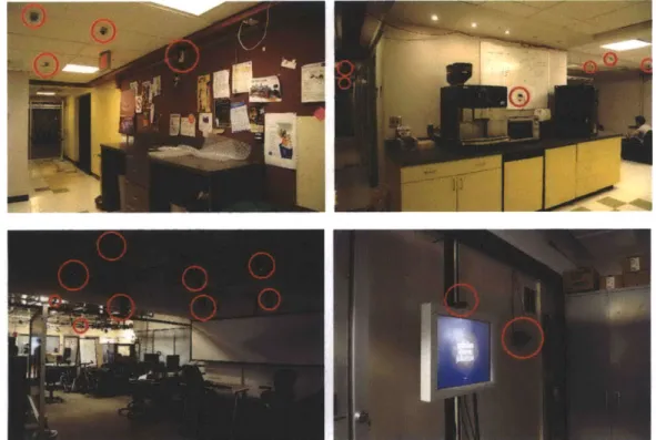
Figure 1.1 A series of pictures taken from common areas in the Media Lab. Each red circle
indicates a sensing device ... ... 18
Figure 1.2 Three layers of privacy aspect in the design of ubiquitous sensor networks. ... 18
Figure 2.1 Left: a MERL motion detector node [8]. Right: the pan-tilt-zoom camera system the MERL team used to compare with the motion detection system. ... 22 Figure 2.2 The design of active badge developed at Xerox PARC in 1991 ... 23 Figure 2.3 The active badge for building comfort control ... 24 Figure 2.4 (a) Two people interacting through their Meme Tag. (b) Close up image of one Meme
Tag. (c) Interaction between two UbER-Badges. (d) UbER-Badge users demonstrating the ability of scrolling text and showing simple animations from the LED array on their U bER -B adges. ... 25 Figure 2.4 Left: USP with an interactive application for sensor data browsing and real time video
streaming from other portals. Right: A user interacting via the USP's touch screen
interface... ... ... 26 Figure 2.5 The environmental SPINNER sensor board ... ... 26 Figure 2.6 Left: an active badge for dynamic management of dense ubiquitous media Right: a
portal that is collecting video of an active badge user. ... 27 Figure 2.7 The virtual extension of a portal from Second Life. Left: One portal view over time,
showing current and past images. Second Life visitors can look at video in the past by touching on the screens that are further back in the virtual portal view. Right: A real world user interacting with the virtual world through USP... ... 28 Figure 3.1 System block diagram . ... ... 30
Figure 3.2 After pressing the "NO" button on a privacy badge, the USP blocks all data transmission and start the 10 seconds count down. The badge also counts down and
informs the users with blinking from the four LEDs and buzzing from the vibration motor.
... 3 1 Figure 3.3 (a) A fully assembled Privacy Badge. (b)(c) Privacy level indication and notification
through the output of light and vibration ... ... 32 Figure 3.4 Sign up page of the web interface. The only information collected by the data server is users' randomly assigned badge ID. ... 33 Figure 3.5 The login page of our web interface ... ... 34 Figure 3.6 The "edit sensor" page allows users to click on each nodes from a map and edit sensor
setting on a location basis. ... ... 35 Figure 3.7 The "edit all sensors" page allows users to set up all sensor preferences regardless of
their location. ... 36 Figure 3.8 The "Edit Group" page allows users to reveal and share information such as images
and videos taken by the USPs with different group of people ... 37 Figure 4.1 Block diagram of the active privacy badge's hardware system. ... 40 Figure 4.3 Microprocessor on the PCB design ... 41 Figure 4.4 Left: The red circle indicates the CC2480 ZigBee processor. Right: Antenna extended
from the front of PCB . ... 42 Figure 4.5 The diagram shows how a host processor interfaces with CC2480 ... 43 Figure 4.6 Left: the Infrared transceiver modules' layout on our PCB design. Right: block
diagram of the IR receiver module. ... 44 Figure 4.7 Power flow diagram of the system power-path management IC (bq24030). The power
source can come from the USB port, AC adapter or the battery ... 45 12
Figure 4.8 Demonstration of charging the battery and powering the system from a USB cable. 45
Figure 4.9 Output devices on the badge... 46
Table 4.1 The ZigBee packet structure. ... 47
Figure 4.11 Pulse width encoding protocol for IR digital signal transmission... 48
Figure 4.12 A standard IR packet in our protocol ... ... 48
Table 4.2 IR packet protocol ... 48
Figure 4.13 Diagrams showing how middleware works. ... ... 49
Figure 4.14 Data structure in the MySQL database ... ... 50
Figure 5.2 Distribution of age and gender of the participants. ... .... 54
Figure 5.3 Distribution of background of the participants... ... 54
Figure 5.4 Necessity of surveillance systems ... ... 55
Figure 5.5 Importance of a context aware sensor network ... 56
Figure 5.6 Importance of privacy control for each individual ... 56
Figure 5.7 Whether ubiquitous computing in a building is necessary ... 57
Figure 5.8 Whether sensor system near their work place is invading their privacy. ... 58
Figure 5.9 Whether high resolution camera and voice recognition on cell phone is necessary.... 59
Figure 5.10 Whether the user enjoys the advancement of new multimedia technology... 59
Figure 5.11 The everyday routing information provided by one user... 60
Figure 5.12 The everyday routing information provided by every user on the 3rd floor. The five plots show five different office areas and the routing information of users from those areas . ... 61
Figure 5.13 Overall percentage counts from the daily routing provided by 24 participants. Note that the most frequent visited areas are the common areas - elevator, kitchen area, and two intersections connecting offices to the major path ... 62
Figure 5.14 Average usage of the blocking button on privacy badges. The upper left figure shows
the count of button presses from 23 users everyday. ... ... 63
Figure 5.15 Average number of active user over time ... ... 64
Figure 5.16 Ratio of button presses and the number of users at that time... 65
Figure 5.17 Visualization of button presses vs. location. Note the difference in the locations counts vs. Figure 5.13 could be derived from the online privacy setting ... 66
Figure 5.18 The percentage of users that chose to block each sensor from the broadcasting of their active privacy badge. ... 67
Figure 5.19 online pre-set sensor preferences for nodes in the kitchen area. ... 67
Figure 5.20 Average percentages of disabled portals over time. The average percentage of disabled portals is 8.06 percent ... 68
Figure 5.21 The results of post-experiment questionnaire... ... 71
Figure A-5: Node PCB Layout Top Overview... 85
Figure A-6: Node PCB Layout Button Overview... 86
Figure A -7: N ode PCB top Layout ... ... 87
Figure A-8: Node PCB Button Layout... ... 88
Figure A-9: Node PCB Middle Layer 1 Layout... 89
Figure A-10: Node PCB Middle Layer 2 Layout... 90
Appendix A for COUHES application- Questionnaire ... ... 99
Chapter 1
Introduction
Whenever a conflict arises between privacy and accountability, people demand the former for themselves and the latter for everybody else. -David Brin
We live in a world where advanced technology has made the production of extremely cheap, small yet powerful wireless sensor networks possible. The clusters of this electronic nervous system, unlike security surveillance systems on the street, have begun to invade our dwellings under the guise of household appliances and communication/media interaction devices. With the great capability of capturing high quality video and audio plus the current facial recognition technology, we might soon be living in the Orwellian nightmare without knowing it [1]. As researchers develop smarter, faster and more complex ubiquitous computing sensor networks, privacy issues are still yet to be solved. It will only become worse as invasive media capture eventually becomes an intrinsic property of devices scattered all over our environments.
In this research, we have constructed a system that allows users to control and configure their privacy within a ubiquitous sensor network from both online (pre- and post- processing) via a web interface and onsite via a privacy badge.
The construction of this system started from developing a multimodal sensor and display network, the Ubiquitous Sensor Portals [2-4]. This sensor network can communicate with wearable privacy badges through a ZigBee radio network and change the sensing parameters onsite, i.e. turn on or off different sensors according to the settings of each individual badge user. Users can setup their privacy preference online by editing the sensor settings of each node and post process their recorded data from a web interface. The privacy level can also be dependent on the group status of the client browsing the sensor network-the badge user can assign different levels of privacy to different groups of people (e.g. taking an analogy to UNIX file system permission: "user/group/world"). Physical means of providing immediate privacy are also afforded (e.g., physically obstructing the sensors). Also, users can also scrub (or selectively "blur") any archived data.
Unlike other systems designed for enhanced privacy protection (see Chapter 2.1), our system leaves all the control to the users with our active privacy badge. The experimental design for our user study focuses on changing different parameters of this sensor network, for example, the default settings (opt in or out), and the processing of information (broadcasting or recording). Therefore, our major contribution to the research of privacy will be providing a user-centric privacy platform for ubiquitous computing and, for the first time, using this platform to obtain real-time experience with user feedback towards privacy within different scenarios, and default settings in a distributed dense sensor network.
1.1 Theory
For years, the study of privacy in ubiquitous computing has focused on designing privacy protocols. System designers construct their own privacy protocols either based on assumptions from their own education, religion, and social background or a survey about privacy concerns from a limited number of users. They either define "private zone's" in a building, or use a context aware system to identify a possible "private scenario" [5-6]. After deciding on the complicated sensing algorithm, they declare their system to be privacy enhanced and able to protect any private scenario. However, a simple question one may ask is: "What situation should be considered private?" Does two people talking softly in a caf6, which is identified by the sensor network via a low audio signal with multiple motion sensor readings and the facial recognition system from the image snap shot, indicate a 100percent private conversation? The
answer is as simple as the question itself: "We don't really know."
"Privacy is the ability of an individual or group to seclude themselves or information about themselves and thereby reveal themselves selectively. " [7]
Admittedly, we system designers have overlooked one very important aspect of privacy for a long time - the dynamic nature of privacy. From the above definition of privacy, we can see that privacy is the ability of individuals to reveal themselves selectively. However, the existing systems only allow a fixed parameter that will define everyone's privacy opinion regardless of the difference between time, space and individuals. Our brain is a very sophisticated machine plus, as the definition for privacy is in an ambiguous gray zone, it is extremely difficult to conclude a general rule for privacy that can suit all ages, genders, cultural backgrounds, and education levels. Rather then trying to automatically deduce a desired level of privacy for everyone, it is much more trackable to allow users to change their settings and control the sensors on site instantly - through user-centric control over sensor-related privacy that exploits pre-established privacy preferences.
The problem does not end there. On the users' ends, there is almost no way for the users to access the information gathered by those sensor networks, not to mention having control over their personal information flow and customized privacy settings. The only option for the users is to trust the system and think that they are safe because of the accountability of system designers. Meanwhile, they try to stay away from the sensors as far as possible to protect their privacy making it impossible to realize the original goal of having a smart sensing and media interacting infrastructure in a modem building.
For example, Figure 1.1 is a series of pictures taken from the common area at the MIT Media Laboratory. Each red circle indicates a connected sensor node. There are at least 5 different sensor networks involved, including MITes [8], foodcam [9], Sociometric badges [10], G-speak [11] and Ubiquitous Sensor Portals [4]. Undoubtedly, it is an environment with dense sensor networks. It is also a very confusing space, since people have no control and almost no knowledge about the technologies around them. Although we trust our colleagues' administrative accountability and believe that those systems are well-designed for privacy protection, there is still no interaction between users and sensor systems provided. N. Aharony [12] suggests that networked devices should be able to act on our behalf to other people and devices around us in a manner analogous to the way humans naturally interact with one another. In the same way, any privacy system should be configurable, allowing users to dynamically change the resolution of personal information exposed to and by the system differently for different groups of users. Thus, from this approach, ubiquitous computing's goal of rich interactions in context aware
environments will be gracefully balanced against the dynamic and varied concerns of privacy. Therefore, in this research, we focus on what we will call the logical layer of privacy control (Fig.
1.2).
Figure 1.1 A series of pictures taken from common areas in the Media Lab. Each red circle indicates a sensing device.
Configurable representation of
sensor data / Controllable personal
data flow
Sensor selection
Sensing direction
Figure 1.2 Three layers of privacy aspect in the design of ubiquitous sensor networks. Instead of focusing on the code layer and basic system vulnerability (network security and
code or hardware verification, which are active areas of research in practice [13]) or the physical layer (sensor selection or sensing region), we create a new approach which aims at giving each user dynamic privacy control for various sensing modalities with the configurable wearable device - an active privacy badge. In a ubiquitous sensor network environment, there will be too many nodes in the environment to be able to manually mask or deactivate and granting access on each sensor node isn't a feasible task to explicitly do. Consumers will not accept devices into their environment unless they feel some control over the information leakage - the market will dictate the need for standards and verifications to maintain the knowledge of controllable privacy. Therefore, with an active badge system broadcasting privacy preferences to the local vicinity, the environment can automatically throttle data to maintain appropriate privacy levels.
Furthermore, an accessible server for sensor data display will enable users to post-process their information flow, delete or restrict any recorded data and adjust their privacy resolution to different groups. This approach, unlike the previous privacy protection work, aim at giving users a measure of control over and peaceful coexistence with the massive, dense, ubiquitous computing sensor networks coming in the future. Therefore, instead of developing rules for system designers, the focus of this research is about managing privacy in various ways at a logical level - how people manage their own privacy rather than secure it from the system designers' end.
Chapter 2
Background
"Conscience is the inner voice which warns us that someone may be looking."
-H.L. Mencken
2.1 Previous Work
2.1.1 Privacy Research in Ubiquitous Computing
Substantial research has been devoted to the design strategies and policies for approaching privacy issues in a ubiquitous computing environment. The major approach for controlling the privacy status within sensor networks is through constructing secure protocols and code verification mechanisms for system developers to follow and examine as they construct the infrastructure for data acquisition and post data processing. Bellotti and Sellen were pioneers
with their work on privacy in the context of video media spaces based on the experience of the RAVE media space at EuroPARC. They first proposed a framework in 1993 [14] for designing the feedback and control in ubiquitous computing environments and described the ideal state of affairs with respect to feedback or control of each of four types of behavior - Capture (What kind of information is being picked up?), Construction (What happens to information?), Accessibility (Is information public, available to particular groups, certain persons only, or just to one'self?) and Purposes (To what uses is information put?). The argument is that "feedback and control" over information in a ubiquitous computing environment can help preserve privacy.
Drawing upon Bellotti and Sellen's work, many toolkits and infrastructures have been developed to provide programming support and abstractions for protecting privacy in a ubiquitous computing environment. Confab [15], for example, is a personal ubiquitous computing system where data starts with the end-user (from a customized instant messenger) and can optionally be disclosed to others in a limited manner. It provides basic support for building ubiquitous computing applications with customizable privacy mechanisms. Campbell [16] and collaborators introduced Mist, a privacy control communication protocol, to separate location from identity from a privacy-preserving hierarchy of routers that form an overlay network.
Researchers also tried to use pseudonym and dummy users to blur users' information, especially location-specific data [17]. Recently, the research of privacy protection in context-aware pervasive systems moves further to the design of self-configuring privacy management infrastructures. Ortmann et al. proposed a self-configuring privacy management architecture for pervasive systems [4]. Further, Moncrieff and coworkers [5] presented a dynamic method for altering the level of privacy in the environment based on the context and the situation within the environment. Besides the research on dynamic privacy configuration in a building, the concept of automatically inferring privacy settings is also used in personal electronic devices such as a cell phone [18-19]. All of the above examples demonstrate the idea of creating a smarter and sophisticated system that could better suit users' need of privacy within the environment. However, without direct user control, the construction of an ideal system that can suit everyone's needs is almost impossible.
Another major method for improving the design of privacy protection in sensor networks is through the physical approach - different choice of sensors and location/direction for the sensing elements. In the technical report from MERL (Mitsubishi Electric Research Laboratories), "Worse is Better for Ambient Sensing", Reynolds and Wren [20-21] examined the ethical implications of choosing camera networks vs. infrared motion detector networks. Their results indicate that for most participants, infrared sensors (Fig. 2.1) were significantly less invasive than pan-tilt-zoom cameras. The design was later adapted and further developed by the House_n group at the MIT Media Laboratory [8], and implemented as a demonstration of a
portable kit of wireless sensors for less invasive naturalistic data collection. The problematic part about this direction, sacrificing the sensing modalities to meet privacy needs, is that in order to provide better feedback and functions for users in a context-aware building infrastructure, merely motion sensor data might be insufficient. Although it is proven that data collected from motion sensing can indirectly lead to approximate personnel identification and localization, a motion sensor network still can not provide the full function of a modem ubiquitous network. Therefore, we try not to compromise our sensor system design, but rather to control a dynamic privacy level from the users' end with a privacy badge.
Figure 2.1 Left: a MERL motion detector node [8]. Right: the pan-tilt-zoom camera system the MERL team used to compare with the motion detection system.
2.2 Wearable Badge Systems
Wearable devices are by far the most effective method for connecting individuals with ubiquitous sensor networks. There are two major types of badge systems: active badges and passive badges. Active badge systems interact with the environmental sensors and observe how their actions affect them. Examples of technologies that are used in active badge systems include infrared (IR) transceivers, RFID (Radio Frequency Identification) tags, Bluetooth, and ZigBee networks. Passive badge systems sense the signal from ambient environments and receive or send the information passively, for example, exploiting the Global Positioning Systems (GPS) or RFID tags. Passive systems reveal no information about the user to a sensor network. Therefore,
users can have full control over their privacy in a passive badge system. Because of the nature of its low privacy threat, we will focus this review on active badge systems.
2.2.1 Active Badge Systems
In a context-aware sensor network, active badges with the addition of multiple sensing modalities allow those network systems to adapt their functions to better suit the behavior and preferences of badge wearers. One of the first attempts to augment name tags with electronics and enhanced interaction was the active badge developed at Xerox PARC in 1991[22]. The badge (Figure 2.2) broadcasts the identity of its wearer and so can trigger automatic doors, automatic telephone forwarding and computer displays customized to each person reading them.
Control Button
Miro-Proessor
Infrared
LED&
Figure 2.2 The design of active badge developed at Xerox PARC in 1991.
In 1992, Hopper et al. from Olivetti Research developed a simple platform that periodically transmits a modulated infrared (IR) ID to the vicinity, enabling people to be located by the IR receiver network in their facility [23]. Besides simply tracking the location of badge users, an active badge could be used to interact with the building system and provides better control over heating, ventilation, air-conditioning (such as HVAC system) and lighting base on the arrival, departure and routine movement of each individual [24]. One recent example is demonstrated by Mark Feldmeier [25] at MIT Media Laboratory, exploiting dense sensor networks for building comfort control. He built short range RF active badges (Fig 2.3) for building occupants that infer their comfort level in terms of temperature, humidity and lighting. Users wear the badge and train this system to adapt their comfort settings from pressing the "too hot" or "too cold" button on the badge during the testing period. With the information, this
23
sensor networks can adjust the building's HVAC system automatically based on users' comfort preferences and minimize energy consumption while best maintaining the satisfaction of the occupants.
Figure 2.3 The active badge for building comfort control.
2.2.2 Active Badge Systems for Group Interaction
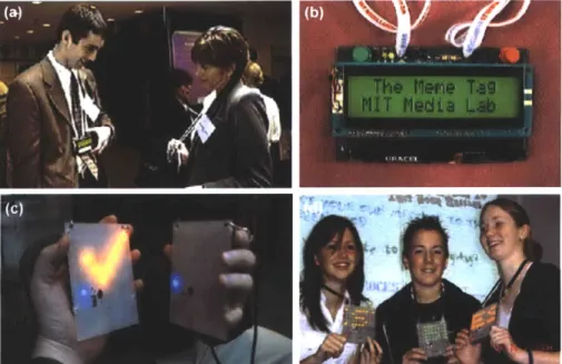
An active badge can also serve as a dynamic display for facilitating person-person interaction at large events. This direction started at the MIT Media Lab from the "Thinking Tag" project [26] that flashes LEDs according to agreement of wearers on a series of provocative questions, and the "Meme Tag"[27] which enabled users to selectively exchange brief catch phrases that can be tracked as they propagated through large groups (Figure 2.3 a,b). The idea of using active badge for group interaction was carried further by Mat Laibowitz with the design of UbER-Badge (Figure 2.3 c,d), a versatile platform at the juncture between wearable and social computing[28-29]. This platform was the first badge prototype that facilitates a variety of group interaction such as viral message passing, analysis of social networking, formation of affinity groups, real time display of social interaction and storing contacts for later retrieval.
The system was later adapted by the Sociometric badge, a wearable computing platform for measuring and analyzing human behavior in organizational settings [30]. The project proposed that through the use of active wearable badges, users' face-to-face interaction, conversational time and physical activity levels can be captured and analyzed to obtain their pattern of behavior. The developers believe the interaction and dynamics between organizations
and individuals can be analyzed and understood through this wearable computing platform.
Figure 2.4 (a) Two people interacting through their Meme Tag. (b) Close up image of one Meme Tag. (c) Interaction between two UbER-Badges. (d) UbER-Badge users demonstrating the ability
of scrolling text and showing simple animations from the LED array on their UbER-Badges.
2.3 Ubiquitous Sensor Portals
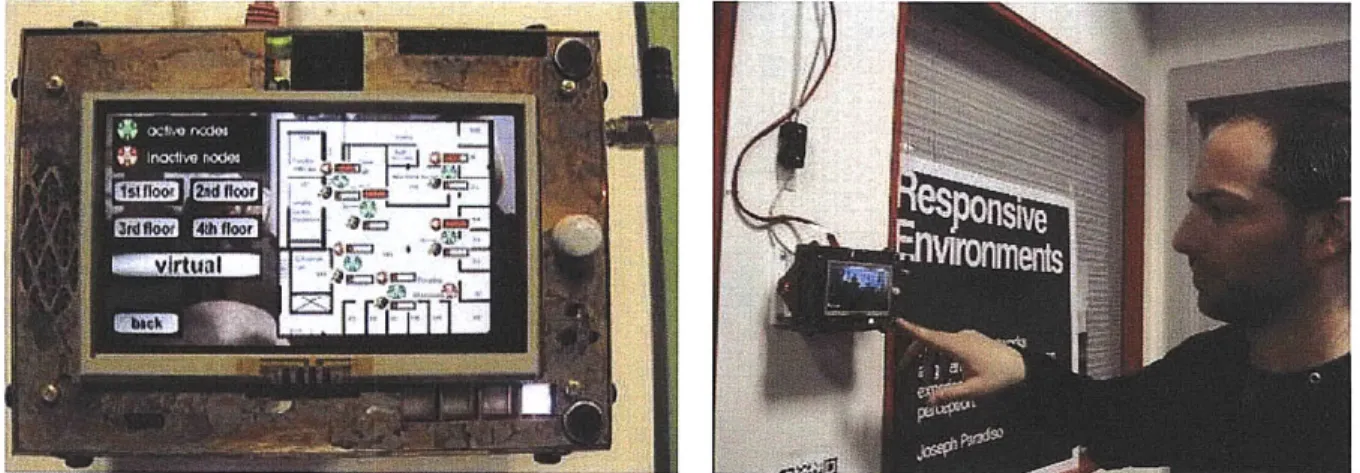
In order to study privacy from the viewpoint of actual users, the first step for this research is to build a highly visible lab-wide sensor network that potentially creates enough awareness for people working in this environment. We call it the Ubiquitous Sensor Portals (USPs). This sensor network was originally designed by Mat Laibowitz to support his SPINNER project [2-3] which will be described in the next section. The 45 portals comprise a sensor network that was distributed throughout the real world Media Lab (Fig. 2.4). Each portal, mounted on pan/tilt platform, has an array of sensors, as well as audio and video capabilities. Video is acquired via a 3 Mega Pixel camera above a touch screen display. The video board is driven by a TI DaVinci processor (an ARM9 running Linux paired with a C64x+ DSP core for video processing), and features a touch-screen LCD display and speaker.
Figure 2.4 Left: USP with an interactive application for sensor data browsing and real time video streaming from other portals. Right: A user interacting via the USP's touch screen interface.
The sensors and an 802.15.4 radio are mounted on a daughter card, which can be connected directly to a wired network for standalone operation or run as a slave to the video board. The sensor board runs off an AVR32 microcomputer (AV32UC3A1256) and features stereo microphone's, PIR motion sensor, humidity/temperature sensor, light sensor, and 2 protocols of IR communication so it can detect and talk to any of the Media Lab's badges (For example, the Sociometric badge, the Privacy badge and the wearable badge for SPINNER applications) that are in the line of sight. The daughter card also supports several status LED's, and the radio communicates with and coarsely localizes many of the wearable sensors that several groups in the Media Lab are developing. The ubiquitous sensor portals are capable of streaming real time sensor data over the network and initiate interactions between different portals.
2.3.1 SPINNER
SPINNER [3] (Sensate Pervasive Imaging Network for Narrative Extraction from Reality) is a novel sensor network system designed to detect and capture fragmented events of human behavior. SPINNER exploits the dense imaging sensor network formed by the USPs that cover
45 different places in the Media Laboratory. The network can collect and sequence the events through a sensor for narrative query and generate videos according to SPINNER's behavior model. The SPINNER network is comprised of wearable sensors (active badge and wristband, Figure 2.6), environmental sensors (Figure 2.5), and video sensors (Figure 2.6) that can identify and record events that fit specific narratives from the high resolution camera. Alternatively, the system can capture all events along with narrative data for cataloging and browsing. It is a platform for studying narratology in order to develop an effective narrative model that can be mapped onto sensor-detectable elements of human behavior.
Figure 2.6 Left: an active badge for dynamic management of dense ubiquitous media. Right: a portal that is collecting video of an active badge user.
2.3.2 Cross Reality Application
The portal platform also supports another application called Cross Reality that involves possible privacy risks. Cross Reality, sometimes referred to as X-Reality, is a framework where events in the real world drive phenomena in a virtual environment that is unconstrained by time, space, or the constraints of physics [31]. Unlike traditional sensors or surveillance systems that record information and store data in a secure server that can only be accessed by system administrator, X-Reality applications broadcast the information to the virtual environment. The problem is that when information is broadcast, it becomes harder to manage the information flow afterwards and track personnel or agencies that obtain the information. Therefore, a Cross Reality event can instigate even more privacy concern than a simple recording. Hence, it is crucial for us to find a solution for privacy protection before ubiquitous media and Cross Reality
events become substantial in our everyday lives.
In our Ubiquitous Sensor Portal system, we used Second Life from Linden Labs to demonstrate the Cross Reality concept. Created by Drew Harry, this virtual Media Lab on Second Life allows visitors to see live video from any of the portals in the real world by touching the screen of the portal with their avatar (Fig 2.7). They can also communicate with the real-world portal by touching a "Talk" button on the portal - initially, communication from Second Life to the real world is through text, but if the request to talk is granted in the real world, audio from the sensor board will also stream from the real world to the virtual portal, enabling 2-way communication.
Figure 2.7 The virtual extension of a portal from Second Life. Left: One portal view over time, showing current and past images. Second Life visitors can look at video in the past by touching on the screens that are further back in the virtual portal view. Right: A real world user interacting
with the virtual world through USP.
From the previous work about privacy research in ubiquitous computing, we have learned that it is important to create a flexible and configurable system that can protect users' dynamic privacy needs. The research on active badge systems further provides a good method for sending individual signals that allow users to provide immediate feedback to the sensor portals and control the sensor systems around them in any locations and scenarios. Therefore, by combining the concept of dynamic privacy adjustment with the work on active wearable badge systems, we designed an active badge system that can be more efficient and effective for privacy protection. More details about the design and implementation of the privacy badge will be discussed in the following chapter.
Chapter 3
Design and Implementation
Sacrificing anonymity may be the next generation 's price for keeping precious liberty, as prior generations paid in blood. -Hal Norby
3.1 System Overview
There are four basic elements in this system - active privacy badges, Ubiquitous Sensor Portals, a data server, and web browsers (Figure 3.1). In this chapter, we describe the design principles of each element. Also, information about experimental setup and user study protocols are provided. In Chapter 4 and 5, we will go though more details on the hardware and software design of each element.
Via ZIgBee Wireless Network
onsite control via a privacy badge Broadcast badge ID evety 5 secs
Via Ethemet Connection Web Browser ee re-
Privacy Badge
-Query settings badge users'pivacyfrom the sener andonline (pre- and post-
System
Overview
change sensor operationsprocessing) control -Tag the information being
via a web interface recorded by the network with
badge ID
Web Server
-PHP (Personal Home page) middle
ware for data query
-MySQL RDBMS (relational database
management system) server
Figure 3.1 System block diagram.
3.2 Privacy Badge
In order to provide active control, people in the sensor network environment are given active wearable privacy badges that broadcast a unique node ID through ZigBee radio every 10 seconds. The badge can also communicate with the portals via an IR transceiver. Users can register on the web interface with this unique set of 4 digits hex ID and edit their privacy preferences on each node (pre-processed privacy). Also, any information recorded (video, audio, motion sensor and the environmental sensor data) will be tagged with this ID so that users are able to post process their own information on the web interface (post-processed privacy).
While the users are wearing their badges within the coverage of our RF signal receiving range, this RF beacon can change the USPs' sensor settings accordingly. If a sudden privacy risk took place, users could block all sensor data recording for 10 seconds with the red panic button (Figure 3.2). After 10 minutes count down, the system goes back to its previous state.
30
... ... ... ... .
Figure 3.2 After pressing the "NO" button on a privacy badge, the USP blocks all data transmission and start the 10 seconds count down. The badge also counts down and informs the
users with blinking from the four LEDs and buzzing from the vibration motor.
In Figure 3.3, we demonstrate one possibility of integrating the electronics into our everyday accessories by assembling the electronics in a case and making it a key chain. The output devices from this design are the four LEDs and the vibration motor mounted at rear. LEDs on the front panel indicate the privacy setting of four privacy levels - video off, audio off, motion sensor off, out of sensing area/total blocking (Figure 3.3(c)). The LEDs can be integrated into illuminated icons with different colored pulses for better indication or even replaced with an LCD. For a user with higher priority (higher privacy criteria), a change of privacy level will trigger the change of other users' sensor settings in the environment. The vibration motor on the badge can inform users of any sudden privacy level changes such as settings being overwritten by someone nearby or the approach of another sensing device (Figure 3.3(b)).
LED indicator IR transmitter
IR receiver
LED indicator
Blac out Button
_Mini- SB connector LED indicator
The privacy level indicators change while the vibration motor informs users
about their privacy level's change
Privacy Level indication
Figure 3.3 (a) A fully assembled Privacy Badge. (b)(c) Privacy level indication and notification through the output of light and vibration.
(a)
LED indicator Zigbee radio Vibration motor (Mounted at rear) '~-" --~"- --- --- --- --- ---~ I --- -- -- 111-311hllll~3.3 Applications on USPs
The role USPs play in this system is to adjust sensors' settings (e.g. on / off of each sensor in different locations) according to each user's preferences. They receive badge ZigBee packets from the sensor board's ZigBee chip and forward this information via Ethernet to the data server. Meanwhile, through the touch screen display, users in the system can get immediate feedback
and control over the network (the "NO" image on the screen in figure 3.2 for example). After USPs receive ZigBee beacon packets from a user on IR line of sight signal (when the users stand
in front of the portals), they query the badge user's settings from the server via Ethernet connection and change sensor operations, such as turning off video recording but leaving the motion sensor on. They also encode users' ID into the information recorded. This allows users to post process their data by sorting through the ownership of the information.
3.4 Data Server and Web Interface
As mentioned in previous chapters, users can register on the web interface with this unique 4-digit hex ID and edit their privacy preferences on each node. The random badge IDs are assigned from the MAC address of each ZigBee chip (detailed codes are listed in chapter 4.5). The sign up page is designed to keep the anonymity of each user. Moreover, anyone can swap their badge and use a different badge ID to remain anonymous (Figure 3.4).
Sign Up
Please enter your username and desired password to sign up. Registration Info Badge_ID: Username: Password: Password (retype): E-mail(optional): Sign Up
Lbacki
login[contact]Figure 3.4 Sign up page of the web interface. The only information collected by the data server is users' randomly assigned badge ID.
33
In the login page, users can read instructions about protocols of this study (Figure 3.5).
Massive amounts of video, audio files, motion sensor data, environmental sensor data, as well as users' privacy settings are processed and stored in log files and then written to a data server. Developed by our fellow Research Assistant from the Responsive Environments Group, Bo Morgan, this server gets registration from all the SPINNER nodes and updates all sensor data and badge packets in to a log file. With a relational database management system (RDBMS), such as SQL or MySQL, we can store the data and query with middleware (such as PHP) and access or edit through a web interface, allowing badge users to control their privacy both online - pre-processing with sensor settings and post-processing from editing/deleting the
information recorded and onsite - via immediate feedback from pressing the blocking button.
Log In
Introduction
Username: Purpose of Study
I I -- Configurable Dynamic Privacy for Pervasive Sensor Networks:
Password: This goal of this research is to study the privacy issue within a ubiquitous computing system through providing a user centric control of their personal privacy setting in a sensor rich environment. There are two sets of different
Ln functionality in a sensor system - broadcasting information for interaction and
recording sensor data for story narrative. We will conduct different sets of
[siln up][ k] experiments base on the fundamental differences of those two functionalities and analyze the privacy issue for future references in the design and
deployment of pervasive sensor networks.
Study Protocol * System Overview
The System consists of two major components. The first component is the
sensor network composed of 45 "Ubiquitous Sensor Portals" distributed throughout the realworld Media Lab. Each portal, mounted on pan/tilt platform, has an array of sensors, as well as audio and video capabilities.
The second part of the system will be a wearable badge- the configurable privacy badge. The badge is built to study the privacy concern and control for users in a pervasive sensor network. The badge can talk to the Ubiquitous Sensor Portals through IRDA, one of the infrared protocol and Zigbee radio, a
Figure 3.5 The login page of our web interface.
3.4.1 Privacy Settings
On the users' end, they can edit sensor preferences on a location basis from the "edit sensor" page. For example, in Figure 3.6, the user is editing node 311 and turns off the video recording at this location. The design aims at getting information to adjust the privacy level of each location with users' sensor settings. We also provide an "edit all sensors" page (Figure 3.7) for people who do not feel like clicking on each node. Results from the data collection on this page can give us more insight about whether specific locations or the nature of different sensors is the greatest privacy threat for most people. In our first experiment, the default setting for all sensors is on (an opt out system that can generalize to higher-level sensor-derived features).
Besides allowing badge users to control the sensors around them, this web interface also provides a means to share your information recorded by the USPs with your friends. In the "edit group page", users can profile their group permission to customize how they appear to who is looking.
Edit Profile
You are logged in as nanwei. [Lo rbackl Preference Settings
Select Floor: . 3rdfloor
You are now editing node311
Figure 3.6 The "edit sensor" page allows users to click on each nodes from a map and edit sensor setting on a location basis.
35
You are logged in as nanwei Floor 3.
Node 311. Preference Setings Video: 0 On Off Audio: On 0 Off Motion: 1 On0 Off
submit Clote Window
Hello namnvei
Preference settings for all nodes Camera (Video) : 0 On 0 Off Microphone(Audio): 0 On 0 Off Motion sensors: 0 On 0 Off
submit
[bac][Edit Profilel[Edit Groupl
Figure 3.7 The "edit all sensors" page allows users to set up all sensor preferences regardless of their location.
3.4.2 Group Dynamics
One of the most important things for users' privacy protection in a ubiquitous computing sensor network is having the ability to post process our personal information flow. While our system has the ability to collect video, audio and images and display that information recorded for each user individually, it could also be tailored to share users' information with others. In the edit group permission page, the users are allowed to reveal their information according to the hierarchy -- user / group / world, like a UNIX file permission system (e.g. family, friends, and world in real life). Further, the users are able to create their own group and send out invitations for other users to join their group. This framework can not only allow the users to customize how they appear to who is looking, but also can be used as a social networking tool similar to Google tracker, which let you follow your friends' or families' locations in real-time [32].
Edit Group Permission
You are logged mi as nanwei. [Log out] [bak
Preference Settings
Select Floor: 14th floor B
You are now editing node405
SO . r. - O You are logged in as nanwei
c40 404
402 uY 401 403 Floor 4.
Node 405.
OA.. Preference Settings ge
IO
C
..
world
t.. no w *l Irr Video: 0 userO group O world
Ow- Audio: G user 0 roup 0 world
Motion: O user O group 0 world
.. Image: O user O group world
. -s
Another possibility of group sharing and social networking that we are currently developing4JO 0
selectively reveal your location-sensitive information to your social networks. Users can select and invite people to view and comment on the pictures, video and audio regarding you. Figure3.9 is a demonstration of location-based photo sharing on Facebook. Every picture is
automatically captured from the USPs. In our future system, this photo/video sharing mechanism
37 4M %WSW~ 42Mu glr~r t ullu 406 W 0 Dom 37
will enable one to automatically link his/her Facebook account to our web interface that will send friend requests and allow users to join groups from this location-specific social network.
I. . .. .
File Edit View History eookmarks Tools :elp
SX e f ( Lhttp: wwwaFacebookcomprofile php?id=180294708O&v=info#profile.php?id=180294708&v=waR
SMost Visited Getting Strted Latest Headlines Customize Unks Windows Marketplace The Regulatons and T.,
facbo k HiS Prie Fred Ino DSg Z
Nw Gong
Wall Info Photos +
Edit My Profile
Write something about yourself.
Information Networks: Boston, MA Birthday: July 7, 1983 Friends 0 friends
, Find people you know
Photos
1 album See All
SPINNER IS EVERYWHERE
Updated 3
minutes ago
Figure 3.9
What's on your mind?
Attach
CO Options Nw Gong
SPINNER IS EVERYWHERE
4 minutes ago -Comment, Like • Share
Nw Gong
SPINNER IS, EVERYWHERE
I July 16 at 12:33pm , Comment Uke ' Share
RECENT ACTIVITY
[] Nw joined the Boston, MA network. gD Nw joined Facebook.
Example of photo sharing on the Facebook platform.
In conclusion, we have built and implemented a privacy-aware social networking and interactive media system throughout the MIT Media Laboratory. Users' anonymity and privacy are carefully protected during the process of data acquisition. The following chapter will cover details about the hardware design of privacy badges.
Remove ,i ? I
--Chapter 4
System Design
"When a man assumes a public trust, he should consider himself as public property. "
-Thomas Jefferson
4.1 Hardware System
To implement the concept of using wearable active badges for privacy control, we built a hardware system comprised of 30 privacy badges that can communicate with the Ubiquitous Sensor Portals via ZigBee radio and Infrared transmitter. This wearable badge design aims to be as simple and small as could be in order to maintain light weight and be used as an everyday accessory, such as a keychain or a necklace. Another important aspect of badge design - the user interface for wearable badges - is also considered and discussed in the later chapters.
The system block diagram is shown below (Figure 4.1). Each node requires processing (microcontroller), communication (ZigBee radio and IR transceiver), and power management (rechargeable power source) capabilities as well as output devices, such as a vibration motor and LEDs to indicate current privacy status.
Figure 4.1 Block diagram of the active privacy badge's hardware system.
Figure 4.2 is the picture of our printed circuit board (PCB) layout. Each badge is powered by a 3.7V, 540mAh rechargeable lithium polymer battery. The top side of this board includes a MINI USB connector for charging the battery with a USB cable, 4 LEDs, IR LED, IR receiver, power switch and a big red button for ease of pressing.
/
jjjj
jj
Ir
Figure 4.2 Badge hardware top (left picture) and buttom (right picture).
On the bottom of this board, we can see the MCU (AT32UC3B164), ZigBee network 40
-- II
processor (CC2480), the power management ICs - step-down converter (TPS62050) and a single chip charge and system power-path management IC (BQ24030). The complete schematics, printed circuit board layouts, bill of materials are listed in Appendix A.
4.1.1 Processing
Each of the battery-powered nodes is controlled by an AVR32 32-bit microcontroller (MCU, here we use AT32UC3B164). The AT32UC3B is a complete System-On-Chip microcontroller based on the AVR32 UC RISC processor running at frequencies up to 60 MHz. It has 16K of SRAM and 64KB of flash for program storage. The power supply is a single 3.3V from the regulated battery power. The AVR32UC is a high-performance 32-bit RISC microprocessor core, designed for cost-sensitive embedded applications, with particular emphasis on low power consumption, high code density and high performance [34]. Two external oscillators are used in the processing circuit. One is an ultra small surface mount type 12 MHz crystal oscillator (NX3225SA, 3.2 x 2.5 x 0.55 mm, 17mg). Another external 32 kHz oscillator (FC-135, 3.2 x 1.5 x 0.8 mm) is also included in the processing module for power and clock management. This ultra-low power oscillator is used when the processor goes into a low power mode. In the low power mode we chose, all synchronous clocks are stopped, but oscillators and the Phase-Lock-Loop (PLL) are running, allowing quick wake-up to normal mode from RTC (Real Time Clock) or external interrupt (EIC) sources. This processor also features 7-Channel 16-bit Pulse Width Modulation Controller (PWM) and one Master/Slave Serial Peripheral Interfaces (SPI) with Chip Select Signals. In order to minimize the size of this board, we choose the smallest 48-pin QFN packaging.
Figure 4.3 Microprocessor on the PCB design.
Two communication methods were chosen in this design to provide long and short range data transmission. For the long range communication, a ZigBee radio network was chosen to provide a 10m-75m signal range in the building. For the short range communication, an IR Receiver Module and IR LED were selected.
* ZigBee Radio
ZigBee technology is a low data rate (250kbps at 2.4GHz), low power consumption, low cost, and wireless networking protocol targeted towards automation and remote control applications build around the IEEE 802.15.4 standard. The specific module used there is Z-Accel 2.4 GHz ZigBee chip (CC2480) from Texas Instruments [35]. The CC2480 is an IEEE 802.15.4-compliant 2.4 GHz DSSS RF transceiver which provides wide supply voltage range (2.0V -3.6V) low current consumption (RX: 27mA, TX: 27 mA) and fast transition times. The 7x7mm QLP48 package chip is shown in Figure 4.4. A single-ended monopole antenna with a Balun network between the trace wire differential output and the antenna is designed for our short range application. Monopole antennas are resonant antennas with a length corresponding to one quarter of the RF electrical wavelength (W4). The length of the V/4-monopole antenna is given by:
4 *L = c/f
Where f is 2.451GHz (for ZigBee channel 11) and c is 2.998x10^8 m/s, a W4-monopole antenna should be 30.59 mm (Figure 4.4).
Figure 4.4 Left: The red circle indicates the CC2480 ZigBee processor. Right: Antenna extended from the front of PCB.
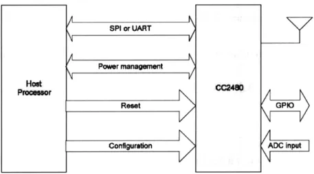
The CC2480 interfaces to any microcontroller through an SPI (Serial Peripheral Interface 42
Bus) or UART (Universal asynchronous receiver/transmitter) interface. In this design, the SPI interface was selected, allowing the microprocessor to control the ZigBee radio through TI's Simple API commands. Figure 4.5 shows the interfacing between a processor and the CC2480 chip.
Host
Proesor CC248
GPIO
ADC input
Figure 4.5 The diagram shows how a host processor interfaces with CC2480
Besides the SPI interface, there are three other hardware interfaces between the host processor (AV32UC3B) and CC2480.
1. Power Management: This interface (only used if SPI interface is selected) consists of
two signals (SRDY and MRDY) and is used to communicate the power management status and to wake up sleeping devices. The host processor can run in sleep mode and wait for an interrupt wakeup to save power.
2. Reset: The host processor can reset the CC2480 through the RESETN pin (hard reset). In addition, a software reset interface is provided.
3. Configuration: This interface consists of the CFGO and CFG1 pins on the CC2480, and
is used to select SPI or UART transport and to select whether a 32 kHz crystal is installed.
In addition, several other configuration parameters may be configured on the CC2480 through the software interface.
1. ADC inputs: the CC2480 has an onboard 12-bit ADC and 2 ADC input pins (AO and Al).
A software interface is provided for the host processor to perform an ADC conversion and read the value. For example, a built-in temperature sensor and battery monitor can be also read through the ADC interface.
2. GPIO pins: Four configurable GPIO pins (GPIOO-3) are available on the CC2480. A 43
SPI or UART
Powver management
Reset
software interface is provided for the host processor to read, write and toggle the GPIO pins. In our design, two LEDs (D91 and D92 on the front) are connected to the GPIO pins on CC2480 to indicate the current network status of each node (i.e. a coordinator, a router or an end device).
3. Non volatile parameters: This software interface allows the host processor to store and access 4 2-byte parameters and 2 16-byte parameters in the non volatile memory of the CC2480.
4. Software timers: Up to four software timers may be configured by the host processor on
the CC2480.
* Infrared Module
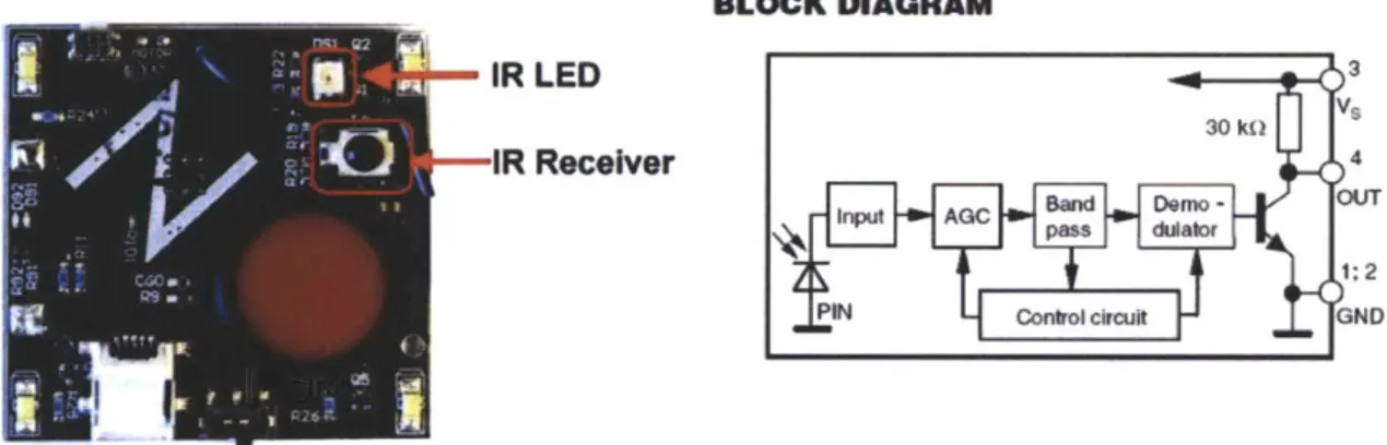
In order to provide a short range communication method for face-to-face interaction between badge users and the sensor portal, an IR receiver module (TSOP36238) was selected for receiving the IR data transmission. The TSOP36238 is an IR receiver module for the remote control system. A PIN diode and preamplifier are assembled on a lead frame; the epoxy package is designed as IR filters (Figure 4.6). The demodulated output signal can directly be decoded by a microprocessor. The 3 V supply voltage can support all major transmission codes. An IR LED was selected to pair with the IR receiver module for data transmission (Figure 4.6). This IR LED is connected to a PWM channel of the microprocessor for generating precision output. Via its 38 kHz carrier frequency, the information can be modulated and transmitted by various IR protocols. On the receiving end, the IR receiver module demodulates the signal and sends the output to a timer on a microcontroller.
BLOCK DIAGRAM
IR LED 3
30 kit
IR Receiver 4
input AGC d Demo
-pass dulator
1:2
PIN Control circuit GND
Figure 4.6 Left: the Infrared transceiver modules' layout on our PCB design. Right: block diagram of the IR receiver module.
4.1.3 Power Module
One of the most critical issues in the design of an active badge system is the power consumption. Although ZigBee is a low-power radio networking technology (RX: 27mA, TX: 27 mA), for an active badge system which requires a constant transmission, battery life can still be a
serious challenge. Here, we use a single-chip charge and system power-path management IC (bq24030 from TI [36]) for charging the lithium polymer battery via a USB port or an AC adapter. The chip can support up to 2 Amperes (A) and charge the battery up to 4.2 Volts (V). Moreover, it can power the system while independently charging the battery, which reduces the charge and discharge cycle on the battery, allowing proper charge termination. The design of this chip makes it possible to supply power to the system from AC, USB, or battery sources continuously (See Figure 4.7). It is also possible to provide feedback of the charging status via LEDs or the output to the MCU. Here, we use two 0603 package LEDs (green Dl and red D2) to
indicate the charging status. During charging, the red LED is on (Figure 4.8); when the fast charging is completed, the green LED will be on while the red is off. The chip pre-charges the battery when it is really low (<3V) and indicates the status with both LEDs on. In order to regulate the output voltage to provide the MCU with 3.3V, a step down converter chip (800-mA Synchronous step-down converter, TPS62050, 10 pin MSOP package) is also included in this circuit.
POWER FLOW DIAGRAM
AC Adaer AC 12 1 OUT
Figure 4.7 Power flow diagram of the system power-path management IC (bq24030). The power source can come from the USB port, AC adapter or the battery.
Figure 4.8 Demonstration of charging the battery and powering the system from a USB cable.
4.1.4 Output Devices
To provide instant feedbacks for the users, two output devices are provided on this badge. The first type of feedback, vibration, is from a vibration motor mounted on the back. The shaft-less vibration motor (310-10 Precision Micro-drives) we use is a 10mm diameter, 3.5mm thick motor which has an average rated speed of 12000 rpm. The start voltage is around 2.3 V and the start current is 85 mA. The overall vibration amplitude is about 0.8 G.
Another type of feedback is the visual feedback from LEDs mounted on the front of this PCB. Connected to the PWM channels, those LEDs can blink with different brightness for various indications and, in the same time, save the battery life.
Vibration LED
Motor
Figure 4.9 Output devices on the badge.
4.2 Software System
The software infrastructure for our system can be divided into three categories: the firmware for badge and portal communication (which runs on the nodes that sends and receives RF or IR beacons from the USPs and provides instant feedback from the output devices), the middleware that runs between a data server and the web interface and the application software that runs on each USP for providingd interactions on the touch screen. In this section, we will focus more on the communication protocols between each segment.