HAL Id: hal-02419663
https://hal.archives-ouvertes.fr/hal-02419663
Submitted on 19 Dec 2019
HAL is a multi-disciplinary open access archive for the deposit and dissemination of sci-entific research documents, whether they are pub-lished or not. The documents may come from teaching and research institutions in France or abroad, or from public or private research centers.
L’archive ouverte pluridisciplinaire HAL, est destinée au dépôt et à la diffusion de documents scientifiques de niveau recherche, publiés ou non, émanant des établissements d’enseignement et de recherche français ou étrangers, des laboratoires publics ou privés.
development
D. Plancq, L. Cachon, A. Woayehune, T. Verpoest
To cite this version:
D. Plancq, L. Cachon, A. Woayehune, T. Verpoest. Progress in the astrid sodium gas heat exchanger development. International Conference on Fast Reactors and Related Fuel Cycles Next Generation Nu-clear Systems for Sustainable Development (FR17), Jun 2017, Yekaterinburg, Russia. �hal-02419663�
Progress in the ASTRID Sodium Gas Heat Exchanger development
D. Plancq(a), L. Cachon(a), A. Woaye hune(b), Th. Verpoest(b)
(a) French Alternative Energies and Atomic Energy Commission (CEA), F- 13 108 Saint Paul Lez Durance, France (b) AREVA NP, F- 69456 Lyon, France
E-mail contact of main author: [email protected]
Abstract. Within the framework of the French 600MWe Advanced Sodium Technological Reactor for Industrial Demonstration project (ASTRID), a Gas Power Conversion System (PCS) based on a Brayton cycle is studied. This innovative option has never been implemented in any Sodium Fast Reactor and is mainly justified by safety and acceptance considerations in inherently eliminating the sodium-water and sodium-water-air reaction risk existing in Steam Generators with a Rankine cycle.
The present work describes the progress in the design of the ASTRID innovative compact Sodium Gas Heat Exchanger (SGHE) and highlights the industrial challenges this technology raises.
This paper presents the details of the design of the SGHE which allows a high thermal compactness. The main studies supporting the development are described whether on the external pressure vessel or on the compact internal heat exchanger modules.
At last, the qualification process is presented through a number of qualification phases at different scales.
Key Words: ASTRID, Heat Exchanger, Sodium, Nitrogen
1. Introduction
In the framework of the CEA R&D program developing the Advanced Sodium Technological Reactor for Industrial Demonstration (ASTRID), the present work describes the current status of an innovative compact heat exchanger and highlights the industrial challenges this technology raised. One of the main innovative options under investigation for ASTRID is the use of a Brayton cycle gas-power conversion system [1]. This system permits to avoid the energetic sodium-water interaction, which can occur in steam generators in case of tube failure if a traditional Rankine cycle is used. In this novel concept, steam generators would be replaced by a Sodium Gas Heat Exchanger (SGHE) [2], [3].
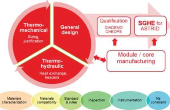
The development of SGHE requires different fields of studies as shown in figure 1.
Figure 1: Different fields of R&D needed for the SGHE development
The design and the qualification of component mainly relies on three disciplines in strong interaction [3]: (i) thermalhydraulics allows to define heat transfer surfaces taking into account the requirements in terms of efficiency and the heat exchanger technology, (ii) the
design study which proposes a 3 dimensional view taking into account technological constraints, (iii) the thermomechanical analyses allow to justify the design.
This design process is iterative, and is powered by R&D conducted on materials and physical chemistry. It also should consider constraints resulting from regulatory aspects, industrial capabilities and the use of sodium.
It is required that the designed object is feasible industrially: the design must take into account the specificities of the pressurized vessel as well as the assembly process envisaged for the manufacture of the heat exchanger modules. Therefore there is a strong interaction between the teams developing the compact plate heat exchanger assembly process, those in charge of the design of the heat exchanger module and those in charge of the overall SGHE integration.
The engineering of the SGHE overall component was transferred to AREVA NP in March 2016, CEA R&D pursuing design and manufacturing studies on heat exchanger module to continue the improvement of the maturity level. A road map for the development, qualification and industrialization of SGHE was since developed in synergy between ANP and CEA R&D.
The first part of this paper presents the details of the general design of this heat exchanger together with the principal benefits got with such a design. The main studies supporting this development are described.
The second part focuses on the progress in the design and the manufacturing process of the compact plate heat exchanger modules.
At last, the qualification program is presented. The qualification of both the design and manufacturing is made through a number of qualification phases at different scales before consolidating the SGHE in its final version.
2. Functional analysis of the SGHE
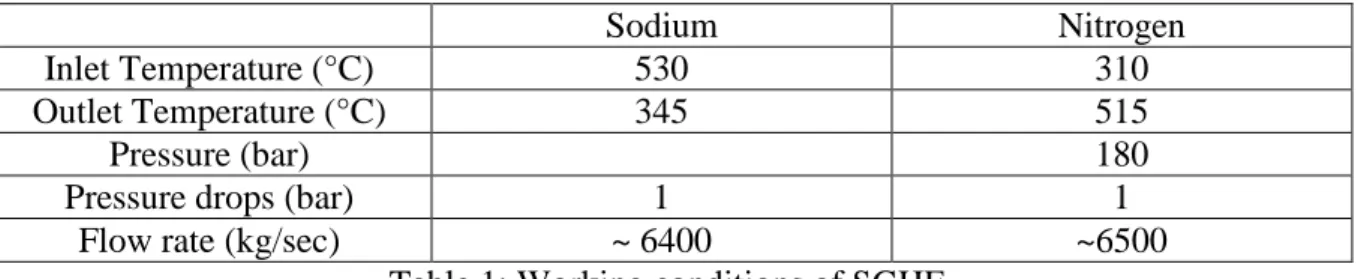
The SGHE has to transfer a total heat power of 1500 MWth between the 4 secondary sodium loops and the 8 gas loops of the power conversion system. The main working conditions of this heat exchanger are summarized in Table 1.
Sodium Nitrogen
Inlet Temperature (°C) 530 310
Outlet Temperature (°C) 345 515
Pressure (bar) 180
Pressure drops (bar) 1 1
Flow rate (kg/sec) ~ 6400 ~6500
Table 1: Working conditions of SGHE
Taking into account the low intrinsic heat transfer capacity of the nitrogen, the design is based on compact plate heat exchangers technology [2]. The principle of the design is to put compact plate heat exchanger modules in a pressurized vessel playing also a header function (figure 2). Each SGHE is composed of 8 modules with a thermal power of about 24 MWth each.
The principle of the design is to put compact plate heat exchanger modules in a pressurized vessel playing also a header function. The main motivations of this design are: (i) the bundle of plates is in compression (this limits the tensile solicitations in the structure), (ii) there is a limitation of constraints due to hyperstatism (each module is free to thermal expansion), (iii) the pressure drops on the gas side are minimized, (vessel acting as header), (iv) the module
access is allowed for the maintenance and inspection, (v) there are 2 confinement barriers between Na and the outside (hence a module failure has no impact on the outside), (vi) the Na inventory is low (<8m3).
3. The Sodium Gas Heat Exchanger Design Component description and principle
The Sodium Gas Heat Exchanger is composed of an external vessel in which compact modules are housed-in. Each module is organized on a base of a series of stacked plates bundle described in the following chapter.
The design of the component pressurized vessel is based on the RCC-MRx 2012 code. Assessment of safety analysis is on-going for this component. On the basis of the safety class level 2, engineering design studies are carried out according to the RCC-MRx mechanical quality level 2 criteria and manufacturing rules.
The heat exchanger component, shown in figure 2, has a thermal power of 187.5 MWth. ASTRID needs 8 SGHE, 2 by secondary loop, to transfer the total heat power to the gas power conversion system. Each SGHE is composed of 8 modules with a thermal power of about 24 MWth each.
Component coolants feeding organisation
The compact plate modules are fed with sodium by means of 32 feeding pipes. Pipes cross through the lower part of the pressurized vessel by the means of thermal sleeves and nozzles implemented onto the vessel lower elliptical head dome. Internal sodium pipes are displayed inside the pressurized vessel, between its lower part and the upper part of plate modules. Each plate module is fed with hot sodium in its upper part, when cold sodium flow-out from plate module on its lower part.
On the lower part of the component, outside the pressurized vessel, two self supporting toroidal sodium headers are installed. The two cold and hot headers feed the 32 “S” shaped external sodium pipes. These “S”shape feed pipes are set-up for pipe thermal expansion accommodation and thermal stress limitation within the structure.
In the upper part of the component, nitrogen gas coolant inlet and outlet are set-up for gas feeding. Nitrogen gas flows in and out the vessel by two large nozzles, allowing the gas pressure drop lowering.
Inside the vessel, an internal shell is installed along the vessel internal skin. Cold inlet gas is flowing in between the pressurized vessel and this internal bell shaped shell. This allows the vessel cooling by cold gas entrance at 310°C. At gas exits from the plate modules, an intermediate common chamber is implemented to collect the gas from all the modules. This chamber is linked to a concentric gas exit duct within the upper gas nozzle. To limit the gas leakage from cold gas inlet and hot gas exit, gaskets system and it support device are set-up in the upper part between the exit nozzle, and hot gas exit duct.
Supports and pressure vessel closing
The plate modules inside the vessel are layed-on on an internal metallic support slab installed inside the pressurized vessel. The support slab is composed of a network of beams that are welded together and fixed on slab periphery on the thick internal vessel by means of consol supports. The slab includes rooms for sodium feed pipe passages.
The coolants organization/segregation with gas feeding on upper part and sodium feeding on lower part favors the component and circuits set-ups optimization within the installation building.
The SGHE component is supported by a large conical skirt installed on the vessel lower part. An annular flange is welded on the skirt basement. The component is anchored to the building concrete slab using 24 studs distributed along the skirt flange. Seismic damping device may also be implemented on the upper part of the vessel.
The pressurized vessel is composed of two parts allowing an opening for in service maintenance / inspection or module replacement. The lower part supports the plates modules and its support slab but also the sodium pipe circuits, whereas the vessel upper part includes the gas nozzles. The vessel can be opened by handling the vessel upper part, without any sodium circuit opening. The two vessel parts are linked together by means of a set of 2 flanges and 46 studs. Leak tightness in between the two vessel parts is granted using two concentric O-ring metallic gaskets implemented near the large vessel flanges.
Pressurized vessel material
For the vessel, the reference material initially retained was the 21/4 Cr 1-Mo or 21/4 Cr 1-Mo -V with the objective of vessel wall thickness minimization. In charge of the vessel design, AREVA-NP recommends to select an alternative material as the 15 CD9-10 grade. The rational of this last choice is the benefits of a large mechanical strength, that is comparable to the 21/4 Cr 1-Mo-V grade, and without lowering the toughness. Moreover when compared with 21/4 Cr 1-Mo -V, the 15 CD9-10 grade have a better weldability. Data base for fatigue resistance or creep behavior remains to be completed for this last grade.
Component design challenges
Designing innovative component requires to face challenges. The sodium-gas plate exchanger component option is a promising component with no past feed-back experience that requires deep validation analyses. Among them the buckling of the hot vessel internals have to be pointed out and focused since they are also subjected to high transients thermal loadings induced by the efficient sodium coolant flow-in.
Since high pressure level near 180 bar is existing within the vessel at steady state, the internal structures housed within the vessel are subject to buckling on the one hand and thermal loadings on the other hand. This includes the internal sodium feeding and discharge pipes but also the connecting sodium headers that are welded to the compact plates modules. Both of them are loaded under compression stresses. One of the main challenges is to design efficiently these sub-parts accounting these two antagonist loadings. One requires thick and stiff structure when the other requires to reduce as far as possible the thickness and the structure stiffness. On-going relevant design studies and optimizations are still in progress. Two large flanges are requested for the closure in between the two vessel parts. To sustain the pressure loading during nominal operating condition and during the pressure validation tests, the thick flanges are designed with 650mm width. The flange sizes are out of current standard limits prescribed into the RCC-MRx design codes and standards (maximum allowed width =500mm). Even if this remains feasible according to the industrial manufacturing process, a specific development/qualification is required for the forged flange validation demonstration. This remains within the feasibility domains, the sizes of forged pieces for SGHE vessel and flanges being not far from the sizes mastered by AREVA-NP.
Sodium is fed by way of 316 L(N) grade pipes. Pipes have to cross through the lower part of the pressurized vessel by the means of thermal sleeves and nozzles implemented onto the 15
CD9-10 grade vessel, in the lower head dome. Bi-metallic welding between stainless steel thermal sleeves and the 15 CD9-10 ferritic grade vessel is to be assumed. Welding tests and qualification process are requested to analyse and validate this Bi-metallic welding option.
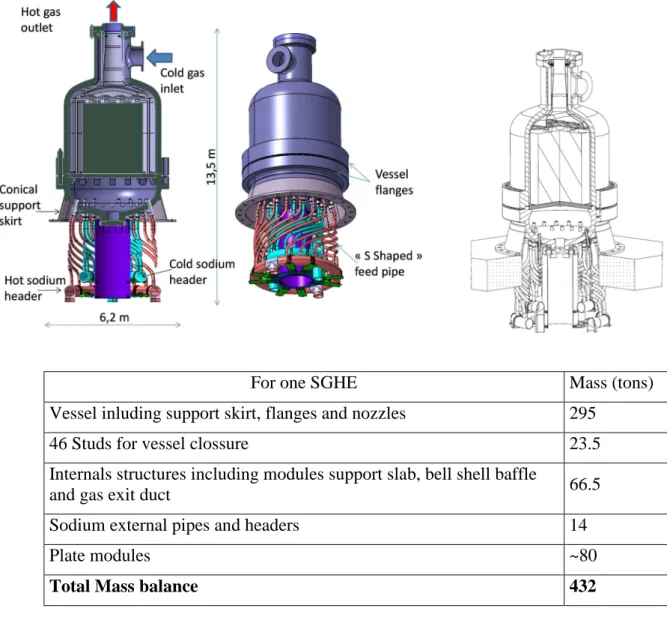
Vessel size and mass balance optimization
The vessel size relies on the interface dimension and space required for modules and internals housed inside the vessel. Currently, the internal vessel diameter required to house all the internals is 4225 mm. The vessel thickness is about 260 mm by taking into account a design pressure of 200 bar, slightly higher than the nominal pressure. With a total height of 13.5 m, the total mass balance for each of the 8 SGHE components reaches about 432 tons (including all the internals, the modules and external pipes and headers). Alternative solutions of vessel design are in progress to decrease the overall weight of the SGHE.
Engineering studies will be pursued to deal with the various challenges expressed above.
For one SGHE Mass (tons) Vessel inluding support skirt, flanges and nozzles 295
46 Studs for vessel clossure 23.5
Internals structures including modules support slab, bell shell baffle
and gas exit duct 66.5
Sodium external pipes and headers 14
Plate modules ~80
Total Mass balance 432
Figure 2: SGHE component vessel
4. The Sodium Gas Heat Exchanger module design and manufacturing process
The core of the SGHE is constituted by the heat exchange modules using the plate machined heat exchanger (PMHE) technology. The principal is to machine heat exchange patterns of each fluid on a set of plates, alternatively stack the gas plates and the sodium plates, and weld themselves by diffusion bonding. The design of each module was made by the help of a large R&D program dedicated to optimize (i) heat exchange pattern on the gas side, which is driven the global heat exchange, and (ii) the sodium header to allow a homogeneous feeding in order to save the thermal efficiency of the heat exchanger but above all to limit the thermal loading of the module.
The works made on the gas heat exchange pattern caracterized what could be the maximum thermal compactness reachable using PMHE technology and so what is thermal compactness loss with a more conventionnal heat exchange pattern [3][5]. A set of friction and heat exchange correlation were established in fucntion of the pattern geometry [3]. These correlations allow the thermohydraulical sizing of the module taking into account the specified working conditions (table 1).
The works made on the sodium headers allow to propose an innovative design of the sodium channels outgoing in the header [4][6] improving the sodium feeding. This particular channel design avoid thermal loading due to classical assymetrical sodium feeding, increase the pressure losses to an acceptable level by means of bifurcations (2 levels), allows a pressure correction between the channels and between the plates [6]. This header design were hydraulicaly qualified on DANAH facility (figure 4).
The design of the SGHE module is presented in figure 3.
Module Gas plate Sodium plate Channel section (2x2 mm²) Channel section (3x5 mm²)
Fig. 3 : module desing based on large R&D program [3][7].
ASTRID Project Business Confidential Information, CEA property designs
Manufacturing process
In order to achieve highly resistant modules, the stack of plates must be joined at its periphery but also at its center. Only brazing and diffusion welding can achieve this. Brazing has been discarded in order to avoid brittle compounds in the joints and to avoid contamination of the base material by foreign elements which could impair its properties, for example corrosion resistance under Na environment. For the same reason, homogeneous diffusion welding has been chosen, i.e. no coating (sometimes used as an aid to diffusion welding) has been applied. Due to the large size of the modules and the unavailability of large uniaxial presses, diffusion welding by Hot Isostatic Pressing (HIP) has been chosen [3]. The plates are grooved, cleaned and stacked in a canister. After vacuum outgassing, the canister is sealed and HIP’ed. During HIP, creep and diffusion enable the welding of the plates but channels may deform. The extent of welding and deformation depends on the HIP cycle parameters (pressure, temperature, time).
The performance of the heat exchanger modules relies on three main items: the achievement of expected channel dimensions, the performances of the material, the resistance of the joints. In other words, the development of the manufacturing process aims at providing answers to the following questions: (i) how to minimize the channel deformation, (ii) does the process modify the base metal and if yes, which properties are affected and how much? (iii) how to achieve joints with properties close or identical to base metal? The experimental development has allowed to identify and solve many issues linked to these questions.
The reference material for the SGHE application is a 316L steel grade with controlled addition of nitrogen, controlled impurities and with a small initial grain size.
The base material gets modified in different ways during HIP. The residual delta ferrite is dissolved and the grain size increases. The mechanical properties decrease accordingly, and this can be evaluated using Irvine’s empirical relation [8]. Particular attention was given to grain growth because, since the wall thickness between the two circuits is about 1mm, a too large grain size would question the applicability of design rules and impair the fatigue resistance, not mentioning the corrosion resistance [3].
The influence of the initial material features (microstructure and surface condition) and the process parameters on the microstructural evolution of the material and the interface microstructure have been thoroughly studied [8][9].
The main issues of the classical PMHE difusion bonding process are the control of the contact pressure, impacting the welding quality, on all the plates staking when pattern between two consecutive plates is différent and also the manufacturing control after difusion bonding. To solve these issues, an innovative welding process has been developped [10]. It consists to HIP independantly gas and sodium pairs plates, control them by tranparency using ultrasound technics, HIP the stak of plates pairs, and control the module boundary by ultra sound technics.
5. The Qualification Process
The qualification process of the ASTRID SGHE follows the general requirements of the qualification process of simulation tools, components and systems of the ASTRID Project [11].
The development of this SGHE may be broken down into three main stages [3] :
1. Conceptual studies and related justification calculations: this stage has to provide a certain number of innovations and related patents relative to (i) the design of the component
itself, (ii) the manufacturing process, (iii) the exchange pattern allowing an improved thermal compactness, (iv) the Na collectors to ensure a homogeneous distribution of the modules. These studies strongly rely on theoretical works, partially validated.
2. Analytical validation where the objective is the experimental validation on a reduced scale with simulating fluid, on representative parts of the concepts and models proposed and / or developed in the previous stage. For the thermal hydraulic performance studies, the validations were carried out on the scale of the gas-side channel [3][6] (test sections implementing LASER viewing), Na headers by means of water-to-sodium similarity tests at channel scale and scale 1 on DANAH facility [4] (fig.4).
Fig.4 : DANAH facility. Illustration showing calculated and measured channels outlet velocity profiles [4].
3. Global qualification: the objective is to take into account in a same test all the significant parameters validated individually in the previous stages. For that, it is needed a functional heat exchanger mock-up working with ASTRID conditions. In order to limit the risk and associated costs, two qualifications scales were chosen [3]:
• Small scale: tests on elementary Heat eXchanger (HX) mock-ups with a heat power capacity up to 40 kW. These tests are performed in the DIADEMO facility (Fig. 5) which is part of the PAPIRUS (Park of small Installation of R&D for Utilization of sodium) platform. The objective is to validate the thermal hydraulic performances of the current exchange part, as well as to validate in a preliminary way the thermomechanical behaviour of the bundle of plates and thus the assembly process. These experimental tests have started in 2013 and will contribute to raise the TRL index from 2 to 4.
Complementary to these tests, a series of elementary tests are carried out in parallel on other facilities belonging to the PAPIRUS platform.
Fig.5 : Picture of the Compact Plate Heat Exchanger (CPHE) and DIADEMO facility.
• Scale 1: tests on a large tests facility named NSET belonging to the CHEOPS platform. CHEOPS platform (see figure 6) is a CEA technological platform which is planned to be
built by 2020. It will be a set of large sodium facilities for component or system qualification.
Fig.6: CHEOPS drawing - Integration in the environment
The NSET facility will allow a power exchange up to 10 MWth. This facility is designed to bring validation on the operation and performance of the heat exchanger module (scale ≈1 of the ones foreseen for ASTRID) and components (regrouping a set of modules, scale 1:12) in stationary and transient conditions. These tests have will be performed during the ASTRID Basic design phase. The objective is to qualify in detail the heat exchange, the design (especially the design of the sodium manifold), the manufacturing process with its manufacturing control strategy and the instrumentation for in-service monitoring. These qualification tests will raise the TRL index from 5 to 7.
6. Conclusions
Progress in the ASTRID Sodium Gas Heat Exchanger development has been described focusing on the general design of this heat exchanger, together with the principal benefits got with such a design, and on the design and the manufacturing process of the compact plate heat exchanger modules.
The qualification program has been presented highlighting the different phases at different scales enabling the consolidation of the SGHE design in its final version.
REFERENCES
[1] D.PLANCQ et al., “Progress in ASTRID Gas Power Conversion System Development”, Proceedings of International Conference on Fast Reactors and
Related Fuel Cycles, Yekaterinburg, Russian Federation, (2017)
[2] L. CACHON et al., “Preliminary design of a large scale Sodium Gas Heat Exchanger (SGHE) for the Nitrogen Power Conversion System envisaged on the ASTRID SFR prototype” Proceedings of International Conference on Fast Reactors and Related
Fuel Cycles, Paris, France, (2013)
[3] L. CACHON et al., “Status of Sodium Gas Heat Exchanger (SGHE) development for the Nitrogen Power Conversion System planned in the ASTRID SFR Prototype”
[4] Ch. GALATI et al., “Numerical and Experimental Investigation of Flow Maldistribution in Compact Heat Exchanger”, The 17th International Topical Meeting
on Nuclear Reactor Thermal Hydraulics (NURETH-17), Qujiang Int
’
l ConferenceCenter, Xi
’
an, China,
September 3 - 8, 2017[5] F. VITILLO et al., "An innovative plate heat exchanger of enhanced compactness",
Applied Thermal Engineering (under review, sent in October 2014)
[6] L. Cachon, X. Jeanningros, C. Galati, A. Molla, patent « Module d'échangeur de chaleur a plaques dont les canaux intègrent en entrée une zone de répartition uniforme de débit et une zone de bifurcations de fluide » PATENT FR16 57543, 3 August 2016 [7] K.J. IRVINE et al., “The strength of austenitic stainless steels”, J. Iron Steel Inst. 207
(1969) 379–390
[8] N BOUQUET et al., « Interface formation during HIP-bonding of austenitic stainless steel », Proceedings of the 10th International conference on Brazing, High
Temperature Brazing and Diffusion Bonding, June 18 - 20, 2013 Aachen, Germany
[9] N BOUQUET et al., « Influence of industrial sheet surface finish on interface formation during HIP-bonding of austenitic stainless steel”, Proceedings of the 11th
International conference on Hot Isostatic Pressing, June 9 - 13, 2014 Stockholm, Sweden
[10] E. RIGAL, L. CACHON, I. MORO, patent «Procédé de réalisation d'un module de chaleur à au moins deux circuits de circulation de fluide », WO2014181297 A1
[11 ] G. GAILLARD-GROLEAS et al., “the qualification process of simulation tools, components and systems within the frameworks of the ASTRID project – Description and examples” Proceedings of ICAPP’17, Fukui and Kyoto, Japan, (2017)
![Fig. 3 : module desing based on large R&D program [3][7].](https://thumb-eu.123doks.com/thumbv2/123doknet/12996017.379676/7.892.123.637.616.1073/fig-module-desing-based-on-large-amp-program.webp)
