READ THESE TERMS AND CONDITIONS CAREFULLY BEFORE USING THIS WEBSITE. https://nrc-publications.canada.ca/eng/copyright
Vous avez des questions? Nous pouvons vous aider. Pour communiquer directement avec un auteur, consultez la première page de la revue dans laquelle son article a été publié afin de trouver ses coordonnées. Si vous n’arrivez pas à les repérer, communiquez avec nous à [email protected].
Questions? Contact the NRC Publications Archive team at
[email protected]. If you wish to email the authors directly, please see the first page of the publication for their contact information.
NRC Publications Archive
Archives des publications du CNRC
This publication could be one of several versions: author’s original, accepted manuscript or the publisher’s version. / La version de cette publication peut être l’une des suivantes : la version prépublication de l’auteur, la version acceptée du manuscrit ou la version de l’éditeur.
Access and use of this website and the material on it are subject to the Terms and Conditions set forth at
Heat transfer in silicon microhotplate structures
Beale, Steven; Conté, F.; Delesalle, B.; Albert, D.; Post, Michael
https://publications-cnrc.canada.ca/fra/droits
L’accès à ce site Web et l’utilisation de son contenu sont assujettis aux conditions présentées dans le site LISEZ CES CONDITIONS ATTENTIVEMENT AVANT D’UTILISER CE SITE WEB.
NRC Publications Record / Notice d'Archives des publications de CNRC:
https://nrc-publications.canada.ca/eng/view/object/?id=87d45010-0790-4cae-8475-e09823e7d163 https://publications-cnrc.canada.ca/fra/voir/objet/?id=87d45010-0790-4cae-8475-e09823e7d163
National Research Conseil national Council Canada de recherches Canada
Institute for Chemical Process Institut de technologie des procédés and Environmental Technology chimiques et de l'environment
Heat Transfer in Silicon Microhotplate
Structures
by S.B. Beale, F. Conté, B. Delesalle, D. Albert, M.Post
Paper presented at
CFD 99
7th Annual Conference of the CFD Society of Canada
Halifax, Canada, 30 May to 1 June, 1999, pp. 4-9 to 4-14.
CFD99 Proceedings 4-9
HEAT TRANSFER IN SILICON MICROHOTPLATE STRUCTURES
S.B. Beale1 F. Conté2 B Delesalle3 D. Albert2 M. Post1
1.National Research Council, Ottawa, ON K1A 0R6 2.Institut Catholique d’Arts et Métiers, 44470 Carquefou, France
3.Institut Catholique d’Arts et Métiers, 59046 Lille, France
ABSTRACT
The results of a 3-D analysis of heat conduction in microhotplate structures are presented. These structures are nominally 200µm x 200µm x 5µm, operate at 400 -500ºC, and are composed of several thin layers of materials, one of which serves as a resistive heater. Variable properties of the layers in the structure and surrounding air, including temperature dependence, are accounted for in the calculations. The goal is to obtain temperature uniformity of 10 ºC on the MHP surface. The results for two different designs are presented. Also presented are the results of calculations of the voltage distribution in the heater. This is required to compute the source term in the heat conduction equation, and is obtained by solving a Laplace equation for electrical conduction, subject to appropriate boundary conditions.
1. INTRODUCTION
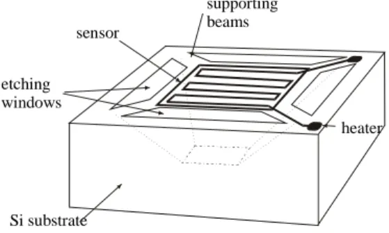
By using silicon bulk micromachining techniques, microsystems and microstructures can be fabricated which have suspended structures operating as microhotplates (MHP). These structures have typical size of the order 200µm x 200µm x 5µm, and can be used in a number of applications [1]. Embedded in the MHP structure is a layer of polysilicon which, because of its resistance characteristics, can dissipate sufficient power to act as a heater. A schematic of the MHP structure is shown in Fig. 1. In certain applications, the MHP must be operated at relatively high temperatures, around 500oC, in a controllable and reproducible manner to ensure spatial uniformity of temperature over the plate surface. It is also important that the region surrounding the micromachined cavity incur no significant temperature rise to avoid damage to control and signal processing circuitry, integrated with the MHP in the adjacent silicon.
etching windows sensor heater supporting beams Si substrate
Figure 1. Schematic of an MHP structure
The present study was initiated to model the heat flux and temperature distribution in two MHP designs, with differing geometries for the imbedded polysilicon heater. Of particular interest were the relationships between the geometric structure of the heater layer, the area of the MHP which could be considered as providing isothermal conditions for the surface film, and the degree of thermal isolation of the nearby bulk silicon
1.1 Previous work
Swart and Nathan [2] considered both steady-state and transient 2-D heat transfer analyses, and assumed the heat flux normal to the top and bottom surfaces to be negligible. The thermal capacity of the MHP considered was presumed to dominate the transient response of the device and convection and radiation were considered negligible. Allegretto et al. [3] used a control-volume scheme to model the transient response of two MHP devices. The approach involved the solution of three 2-D models, involving partial differential equations. Agreement with experimental results was typically within 1-2%. Fung et al. [4] presented a 3-D steady analysis of a MHP using commercial computer aided engineering software.
1.2 The present case
For the present problem, a detailed 3-D analysis was performed for two distinct MHP designs; Mark 1 and Mark 2. In both cases, a structured multi-block mesh was constructed. Figure 2 illustrates the mesh used for the Mark 1 prototype which consists of three-blocks of 14x27x40, 20x20x40 and 30x13x40 cells. For the Mark 2 design a mesh of 17x17x40, 20x34x40, and 14x34x40 cells was constructed. The cells pass through the solid and fluid zones occupied by the silicon substrate, air, beams and layers of the MHP structure, within which mesh lines are concentrated. Owing to symmetry, the Mark 1 mesh passed through one half of the design geometry, while the latter covered one quarter of the domain.
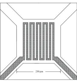
The polysilicon heater is located on layer 2, (see Fig. 3 and Table 1). The heater geometry is shown in Fig. 4. The zone between the Platinum material, illustrated in Fig. 5, defines the target area for the Mark 1 prototype. Figure 6 shows the heater design for the Mark 2 design. The Platinum layer for this model (not shown) is similar to that given in Fig. 5, except that it is symmetric in the y direction, as well as in the x direction.
The analysis considers the case of MHP operation in a quiescent environment, i.e., in the absence of any forced convection. Trial calculations suggested the Grashof and Rayleigh numbers to be 9.8x10⁻² and 6.8x10⁻² at 450ºC. Radiative losses were estimated to be only 2.4%-4.3% of total power input, Q&, in the range 400-500 ºC, assuming an emissivity of 0.7. Convection and radiation were therefore considered negligible.
In the absence of convection or thermal radiation the steady-state energy equation may be written,
div gradk T =S (1) where the thermal conductivity, k, is a function of the location within the MHP and also of temperature. For the present analysis, the source term in the heater,
S (W/m3), was presumed to be the net power consumption per unit volume,
S Q V EI V = & = heater heater D (2)
The implications of this premise are discussed
to capture the details of the heater geometry shown in Figs. 4 and 6, however some layers contain complex sub-scale microstructures, composed of different materials, Under these circumstances the cell conductivity was computed as an effective value,
k
eff=
r k
+
r k
1 1 2 2 (3)
where r1=A1
1
A1+A26
and r2 =A21
A1+A26
are the area fractions of the regions occupied by materials 1 and 2, conductivities, k1 and k2. This type of approximation is often used in problems involving heat transfer in porous media.Equation (1) may be converted to linear algebraic equations [5], and solved using a finite-volume method. The computer code PHOENICS was readily employed for the task at hand. Because of the large variations in thermal properties in the layers of the MHP, interfacial diffusion coefficients were computed using harmonic averaging. The thermal conductivity of air as a function temperature, T (ºC), was computed using linear regression from the data of Vargaftik [6] in the range 27-477ºC as,
kair =6 3973 10. x -5T+2 5471 10. x -2 (4)
2. TEMPERATURE DISTRIBUTION
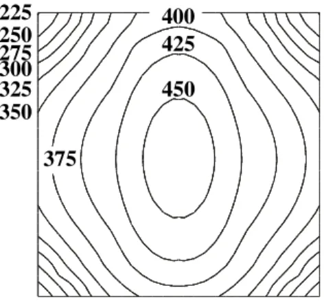
Figure 7 shows the surface temperature distribution for the Mark 1 design, for a power input, Q&, of 34 mW. The maximum temperature of 464°C occurs at the centre of the MHP. From here to the platinum pad, Fig. 5, there is a temperature decrease of 40°C along a horizontal line, or 70°C along a diagonal in the direction of the beams (located at the corners of Figure 7). The desired temperature uniformity is a maximum ∆t of 10 °C between the platinum contacts. The results of these calculations suggest an overheating area at the centre of the MHP, with the conclusion that the Mark 1 heater design is not suitable.
Figure 8 shows temperature contours for the Mark 2 design, for Q& = 30 mW. A relatively uniform temperature distribution is apparent; however inspection of Fig. 8 reveals four overheating areas within the target area, near the location of the heater turns (Fig. 6) where a maximum temperature of T = 433°C is observed. The temperature at the centre of the MHP is 401.5°C. There is thus a range of 30°C in the temperature field within the target area.
CFD99 Proceedings 4-11 Air MHP structure Etched cavity Cells concentrated within MHP
Figure 2. Detail of mesh used in this study of the Mark 1 design.
Figure 3. Vertical layers in Mark 1 and Mark 2 designs.
Table 1. Materials in layers of a MHP
Material Thickness (µm) 1 SiO2 1.0 2 Polysilicon 0.3 3 SiO2 0.8 4 SiO2 0.8 5 Absent 0.0 6 SiO2 0.5 7 Si3N4 0.5 8 Platinum 0.2 230 mµ
Figure 4. Mark 1 design: Plan of the heater layout
Figure 5. Mark 1 design, Platinum layer.
P o ly s i l i c o n h e a te r
150 mµ
Figure 6. Mark 2 design: Plan of the heater layout.
a perpendicular direction from the centre, and by 18°C diagonally towards the beams (prior to decreasing at the peripheral corners,). In both Figs. 7 and 8, the relatively large temperature gradient near the corners suggests that much heat transfer occurs through the beams.
The results for the Mark 2 model, while still not within the 10°C design envelope, represent a significant improvement over the earlier Mark 1 design. The four small hot spots located in the target area, (resulting in a ∆T of 30°C) obfuscate the fact that the temperature distribution over a majority of the area of the surface is quite uniform. This result is encouraging for future developments. The reader will note that the value of the input power, Q&, is a matter for concern: For Mark 2, the temperature at the connection between the MHP and the beam, is higher than for the Mark 1 design (330°C at 30 mW compared to 240°C at 34 mW), owing to improved temperature uniformity. This may lead to mechanical failure as a result of thermally induced stresses: Empirical tests conducted on Mark 1 indicated, that the beam ends failed due to thermal stresses forQ& ≥ 40 mW.
Figure 9 shows the temperature distribution along a line running vertically from the lower substrate through the etched cavity perpendicular to the MHP. The substrate is essentially isothermal at 20°C, due to the very high thermal conductivity of silicon: Large temperature gradients occur in the air above and below the MHP structure. This also suggests that the risk of damage to circuitry in the adjacent substrate to be minimal, provided the silicon is of sufficiently high purity that the thermal conductivity is very large. Experimental measurements [7] were obtained by measuring the black-body emission for Mark 1 geometry, at various operating powers, Q&. An imaging resolution of around 50µm was obtained using a standard microscope objective and a photomultiplier. Calibration was achieved by simultaneously probing a comparable set-up with a thermocouple. The experimental data suggest that for the Mark 1 model, the average plate temperature is
T
= 380 ºC forQ& = 34mW. Inspection of Fig. 7 reveals this value to be well within the observed range lending confidence to the present results.450
425
350
325
300
275
250
225
375
400
Figure 7. Surface temperature distribution, Mark 1 design, Q& = 34 mW
425
400
375
350
325
Figure 8. Surface temperature distribution, Mark 2 design. Q& = 30 mW
Figure 9. Mark 1 design. Temperature distribution in the vertical direction. Also shown is the effect of doubling the mesh in all three directions.
CFD99 Proceedings 4-13 8.39 x 10¹² 3.07 x 10¹¹ 1.12 x 10¹² 1.94 x 10¹² 2.76 x 10¹² 4.40 x 10¹² 3.58 x 10¹² 5.22 x 10¹²
Voltage, E
Source term, S
S constant
7.4 x 10¹² 2.2 x 10¹⁴ 2x10¹⁴ 2x10¹³ 4x10¹³ 6x10¹³ 8x10¹³ 1x10 14Voltage, E
Source term, S
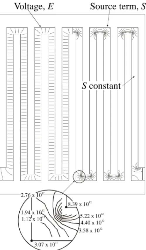
Figure 10. Mark 1 heater. Contours of Voltage, E (V), and heat source, S (W/m3).
Figure 11. Mark 2 heater. Contours of Voltage, E (V), and Heat source, S (W/m3).
3. HEATER VOLTAGE DISTRIBUTION
In the thermal analysis described above, the source term, S, was presumed to be constant, corresponding to a linear drop in voltage, E, along a heater of constant cross section. The impact of this assumption was investigated by computing S according to,
S =gradE¼sgradE (5) where the heater voltage, E, is solved for according to Laplace’s equation,
div grads E = 0 (6) The solution for E was obtained in a 2-D Cartesian mesh, by prescribing Dirichlet boundary conditions at both ends, corresponding to the potential difference across the heater, and Neumann conditions along the sides of the element. The latter was achieved by assuming σ = 0 outside the heater, and using harmonic averaging [5]. For a heater layer, of width,
w, thickness, d, and length, l, the electrical
conductivity, σ, may be related to the resistance, R, and sheet resistance, Rs, according to [8].
R Rw
l d
s= =
1
s (7)
Figures 10 and 11 show details of the voltage distribution, E, and corresponding source term, S, in the Mark 1 and Mark 2 heater elements. It can be seen that for the Mark 1 design, grad E and hence S is quite constant, nominally within ±10% of the constant value presumed in the heat transfer analysis, over the majority of the length of the heater. In the bends, however, E displays the well-known tendency of harmonic functions, i.e. the equipotentials are closely-spaced at convex boundaries and widely-closely-spaced at concave boundaries. It can be seen that S is a minimum of 3.1x10¹¹ at the outside corner and a maximum of 8.4x10¹² at the outside corner (inset Fig. 10). These values are approximately 170% greater and 90% less than the presumed S = 3. 1x10¹² W/m3, and represent a significant, if somewhat localised departure from the presumed boundary condition.
Inspection of Fig. 11 (inset) reveals similar trends to those described above, for the Mark 2 geometry. In addition, variation in grad E also results from changes in the width, w, of the heater. Since E is a conservative function; voltage lines are more dense in regions of narrow width, hence S is reduced in the wider central zones of the heater.
4. CONCLUSIONS
A 3-D design tool for thermal management in MHP structures was developed. Detailed calculations showed that (i) temperature uniformity on the target area approaches, but does not yet meet design specifications, (ii) the degree of insulation from the surrounding substrate appears to be adequate. An investigation of the premise that the heat source may be treated as a constant volumetric source, was performed assuming metallic-type electrical conduction in the heater. The results suggest that this is a reasonable assumption for constant heater width, away from bends, but not for complex variable heater geometries, where it is an idealisation.
5. FUTURE RESEARCH
Future work is required to incorporate the variable source term obtained above, into the 3-D heat transfer calculations. In addition the impact of the temperature distribution upon the stresses in the beams will be studied by simultaneously conducting thermo-elasticity calculations with the heat transfer analysis. It is anticipated that detailed experiments on the local temperature distribution on the MHP structure will also be gathered in the future, in order to validate the results of numerical calculations.
6. ACKNOWLEDGEMENTS
This work resulted from an exchange program of three 5th year engineering students at L’Institut Catholique d’Arts et Métiers (France) at NRC. The work contributed towards an NRC/NSERC/Industry joint research project with Concordia University and Armstrong Monitoring Corporation. The authors would like to acknowledge the contributions of all the partners, and especially those of Profs. David Cheeke and Leslie Landsberger (Concordia) and Dr. Donald Singleton (NRC) for reading the manuscript. Acknowledgements are also due to Dr. Oleg Grudin and Mr. Radu Marinescu (Concordia), who fabricated the MHP's and answered numerous technical questions. We would also like to thank Dr. Simon
experimental data. The technical support provided by Mr. Ron Jerome to our modelling group is also gratefully appreciated.
REFERENCES
1 S. Wessel, M. Parameswaran, S.R. Morrison and R.F. Frindt. "A CMOS Thermally Isolated Heater Structure as a Substrate for Semiconductor Gas Sensors". Proc. Canadian Conference on Very Large Scale Integration, Kingston , 1.6.1 - 1.6.8, 1991. 2 N.R. Swart and A. Nathan. “Design Optimization of Integrated Microhotplates”, Sensors and Actuators A,
43, 3-10, 1994.
3 W. Allegretto, B. Shen, Z. Lai, and A.M. Robinson. “Numerical Modelling of Time Response of CMOS Micromachined Thermistor” Sensors and Materials,
6, 2, 1994.
4 S.K.H. Fung, Z. Tang, P.C.H. Chan, J.K.O. Sin, P.W. Cheung. “Thermal Analysis and Design of a Micro-hotplate for Integrated Gas Sensor Applications”, Sensors and Actuators A, 54, 482-487, 1996.
5 S.V. Patankar. Numerical Heat Transfer and Fluid
Flow. Hemisphere, New York. 1980.
6 N.B. Vargaftik. Handbook of thermal conductivity
of liquids and gases. CRC Press, Boca Raton, 1994.
7 S. Fafard. Personal Communication, April 1999. 8 L.A.A. Warnes. Electronic Materials. MacMillan, London, 1990.