HAL Id: cea-02442288
https://hal-cea.archives-ouvertes.fr/cea-02442288
Submitted on 16 Jan 2020HAL is a multi-disciplinary open access
archive for the deposit and dissemination of sci-entific research documents, whether they are pub-lished or not. The documents may come from teaching and research institutions in France or abroad, or from public or private research centers.
L’archive ouverte pluridisciplinaire HAL, est destinée au dépôt et à la diffusion de documents scientifiques de niveau recherche, publiés ou non, émanant des établissements d’enseignement et de recherche français ou étrangers, des laboratoires publics ou privés.
alkali-activated slag mortars
F. Rifai, A. Darquennes, F. Benboudjema, B. Muzeau, L. Stefan
To cite this version:
F. Rifai, A. Darquennes, F. Benboudjema, B. Muzeau, L. Stefan. Study of shrinkage restraint effects at early-age in alkali-activated slag mortars. IA-FraMCoS-9 - 9th International Conference on Fracture Mechanics of Concrete and Concrete Structures, May 2016, Berkeley, United States. �cea-02442288�
F. Rifai, A. Darquennes, F. Benboudjema, B. Muzeau and L. Stefan
STUDY OF SHRINKAGE RESTRAINT EFFECTS AT EARLY-AGE IN
ALKALI-ACTIVATED SLAG MORTARS
F. RIFAI*,†, A. DARQUENNES†, F. BENBOUDJEMA†, B. MUZEAU* AND
L. STEFAN††
*Den-Service d’Etude du Comportement des Radionucléides (SECR) CEA, Université Paris-Saclay
F-91191, Gif-sur-Yvette, France e-mail: farah.rifai@cea.fr
e-mail: benoist.muzeau@cea.fr
†LMT Cachan – ENS Cachan – Paris-Saclay University Cachan, France
e-mail: aveline.darquennes@ens-cachan.fr e-mail: farid.benboudjema@ens-cachan.fr
††AREVA NC, D&S, Technical Direction La Défense, France
e-mail: lavinia.stefan@areva.com
Key words: Alkali-activated blast-furnace slag mortar, Restrained Shrinkage, Hydration Modelling,
Durability
Abstract: Alkali-activated materials are being increasingly studied nowadays as hydraulic binders.
In order to be enrolled in different civil engineering applications, several properties must be characterized. This study focuses on their cracking risk by shrinkage restraints. This paper summarizes the experimental and modelling results of a project assessing the development of early age properties of an alkali-activated slag mortar. Firstly, an experimental campaign was held in order to quantify hydration heat release and hydration kinetics, determine the time evolution of the Young modulus and the tensile strength and measure free shrinkage strains, all in autogenous conditions. Secondly, two modelling approaches for mechanical properties and shrinkage development were compared. The results showed that the classical approach to characterize the hydration kinetics based on semi-adiabatic calorimetry results isn’t suitable for the studied binder because of slow hydration and low heat release. Numerical work was finally conducted in order to predict stress development of a massive structure of alkali-activated slag mortar subjected to internal (self) and external strains’ restraints (at mesoscopic and macroscopic scales).
1 INTRODUCTION
Hydration processes of alkali-activated materials have been addressed in the literature, but few industrial application are available [1-2]. The main driving factor behind the beginning of adopting alkali-activated materials solutions was the substantial reduction in CO2 emissions accompanying the
Portland cement fabrication [3].
However, experimental investigation, especially those monitoring transport and mechanical properties, showed advantages of using this type of materials as an alternative for Portland cement in some specific applications [1-4].
alkali-activated binders, different applications were possible. In fact, the lower leachability of several species (Pb, Cr, Zn) in BFS binders compared to ordinary Portland cement (OPC) ones [5] and the lower interference of heavy metals with setting and strength development [6], make them a better choice for hazardous materials stabilization/solidification.
Furthermore, BFS concretes have been used in the 1980’s in USSR [4] countries for structural engineering applications. High-rise residential buildings were built using a BFS concrete, alkali-carbonate activated, with a water to binder ratio (w/b) of 0.35.
In fact, BFS binders show in general equivalent or higher mechanical strength [7] than OPC binders at early age, but comparable or lower mechanical strength at long term, depending on the type and the concentration of the activator used. This behaviour is variable according mainly to the type and dosage of alkaline activator used, the mineral composition of the BFS and the w/b ratio. However, BFS binders undergo higher delayed strains [7] than OPC ones leading to higher cracking risks by shrinkage restraints.
Therefore, further investigation of the mechanical behaviour of BFS binders is necessary in order to integrate them in major civil engineering applications. Specifically, stress development caused by strains restraints (by aggregates in BFS concrete, hazardous waste in solidification matrix) should be studied.
The main objective of this project is to provide a thermo-chemo-mechanical model describing the behaviour of a massive alkali-activated slag mortar structure, subjected to internal and external shrinkage restraints.
First, the modelling approach and the experiments used for material parameters identification are presented and discussed. Numerical simulations are then performed both at macroscopic and mesoscopic scales.
2 EXPERIMENTAL WORK AND MODELLING
The analysed composition is a hydraulic binder mortar of BFS activated with sodium
hydroxide (NaOH) solution. The mortar has an initial water to binder (w/b) ratio of 0.5 and a ratio of sand to binder equal to 2.
All the experiments are conducted on specimens kept in autogenous conditions (protected by plastic film and aluminium sheets after demoulding at the age of 24 hours in order to inhibit moisture transfer) and conserved in a controlled room at 25 ± 1˚C and 35 ± 5% RH.
2.1 Thermo-chemical analysis 2.1.1 Modelling strategy
The heat balance including hydration heat release can be written as follows:
= ∇ ∇ + ξ (1)
Where is the volumetric heat capacity [J/m3.K], the thermal conductivity [W/m.K], the hydration latent heat [J/m3] and ξ the degree of advancement of hydration reaction. It is assumed that heat release source is proportional to the rate of hydration of the binder.
The following hydration model is assumed, in which hydration is expressed as a thermo-activated reaction obeying to Arrhenius law by the mean of an appropriate chemical affinity [8-9]:
ξ = ξ exp − (2)
Where is the activation energy [J/mol], the universal gas constant [J/mol.K] and ξ is the chemical affinity [/s].
The volumetric heat capacity and the thermal conductivity of tested mortar were determined experimentally via the hot wire and hot plane methods [10].
Hydration equation and material’s properties identification are detailed in the next section.
2.1.2 Semi-adiabatic calorimetric test results and analysis
using semi-adiabatic calorimetry method (Langavant Bottle NE 196-9) on a cylindrical specimen having a diameter of 7 cm and a height of 16 cm. The specimen was made of the studied activated slag mortar. The results of temperature raise measurements are given in the figure 1.
Figure 1: Temperature evolution in the middle of the
semi-adiabatic calorimeter specimen and ambient temperature.
Hydration heat q [J] development taking into account heat losses is calculated as follows:
= − 0
+ ! + "#
$
# d (3)
Where a [W/K] and b [W/K²] are constants for the Langavant bottle, is total heat capacity of mortar specimen and Langavant bottle [J/K], specimen temperature at time t, 0 initial specimen temperature and # the temperature difference between Langavant bottle and ambient temperature. The paste age was corrected to account for the effect of temperature evolution.
1Cast3m, Commissariat à l'Energie Atomique CEA
- DEN/DM2S/SEMT, Cast3m finite element code, available at http://www-cast3m.cea.fr/
The chemical affinity was then calculated and interpolated using a polynomial function as shown in figure 2.
The thermo-chemical problem can be now solved by implementing the thermal parameters into cast3m1 for finite element simulation.
Figure 2: Identified chemical affinity.
2.2 Mechanical analysis
In order to study the mechanical behavior of alkali-activated slag mortar, an elastic model is used for a first approach.
The Poisson ratio is assumed to be constant. For instance, taking into account its evolution in ordinary concrete showed to be not significant [11]. The Young modulus and the tensile strength & increase due to hydration. Basic creep strains effect is taken into by using simplified effective modulus approach.
The evolutions of elastic Young modulus and tensile strength are determined with respect to binder’s maturity and taking into account the relaxation effect by creep. Elastic strains tensor '() is expressed in terms of total strains ', autogenous strains ' *, thermal strains tensors ' + and basic creep strains ' ,-as follows: 20 22 24 26 28 30 32 34 36 0 5 10 15 20 T e m p e ra tu re [ °C ] Time [days] Specimen Temperature Ambient Temperature 0 10 20 30 40 50 60 0 0,2 0,4 0,6 0,8 1 C h e m ic a l A ff in it y [s -1]
Hydration reaction advancement degree [-]
'()= ' − ' *− '+− ',- (4)
A damage approach is used to describe cracking. Since cracking occurs mainly in tension at early-age (due to the restrain of strains), a Mazars model [12] is adopted with some slight.
The relationship between apparent stresses ., effective stresses ./, damage 0, elastic stiffness tensor , elastic strains '() reads:
. = 1 − 0 ./ (5)
./ = '23= ' − '!4− 'ℎ− '"6 (6)
0 is linked to the elastic equivalent ensile strain '̂
'̂ = 8〈 '23〉;: 〈 '23〉; (7)
Where ⋅ + is the positive part operator. The damage criterion is given by:
& = '̂ − =$ (8)
Where =$ the tensile strain threshold is computed from the evolution of tensile strength & and Young modulus as follows:
=$ = & (9)
Then, D& =0 if
ε
ˆ≤κ
0 and:(
) (
)
[
ε(
ε)
]
ε κ ˆ 2 exp ˆ exp 1 ˆ 1 0 t t At Bt D= − +A −B − − if εˆ≥κ
0 (10)Where At and Bt are constant material parameters which controls the softening branch in the stress-strain curve in tension.
Strain softening induces inherent mesh dependency and produces failure without energy dissipation [13]. In order to avoid such shortcomings, a characteristic length 3- related to the mesh size is introduce in order to dissipate the same amount of energy after mesh refinement, when strains localize in one row of finite elements [14-15].
For the adopted model, the dissipated energy density >?@ at failure in tension reads:
(
)
t t t ft B A f g = 1+ 2 (11)It is related to the fracture energy Gft [J/m²]:
c ft ft l G g = (12)
Since no data are available, parameters coming from ordinary mortar are taken for fracture energy.
To summarize, in order to apply the described modelling strategy, the evolution of mortar strains (thermal and autogenous), Young modulus (taking into account basic creep relaxation) tensile strength and fracture energy should be determined. Thermal strains could be determined from the resolution of Heat equation as shown in the previous section. Remaining evolution laws and parameters are identified based on experimental results as detailed hereafter.
2.2.1 Shrinkage strains evolution
The autogenous shrinkage strains of alkali-activated slag mortar were measured using LVDT on three 4 x 4 x 16 cm specimens, placed in the controlled room.
Figure 3: Experimental results of autogenous. shrinkage
(mean and standard deviation).
Figure 3 illustrates the mean of the 3 autogenous shrinkage strains evolutions with the standard deviation.
The results show that the autogenous shrinkage is not stabilized even at the age of 100 days. This tendency could be related to the slow hydration kinetics of alkali-activated slag. A parasitic mass loss is also possible.
An experimental campaign is currently undertaken by measuring parasitic weight less as well as relative humidity (RH) inside the specimen to unveil some correlation between self-desiccation and autogenous shrinkage. The first approach used to simulate this behaviour was the one supposing that the autogenous shrinkage is proportional to the advancement of hydration reaction degree starting from the mechanical percolation threshold A$:
' * = = A̅
A̅ = 〈AA − A$
C− A$〉;
(13)
This last parameter was taken equal to the set point measured by the Vicat needle method. Experimental results showed that this classical model is not suitable for this type of cementitious material. For instance, the curve giving the evolution of shrinkage strains with respect to A̅ is given in figure 4:
2EC2 partI, Eurocode1, Design of concrete
structures, 1992
Figure 4: Comparison between experimental and
simulated results of autogenous shrinkage Eq.13.
The results show that the evolution of shrinkage strains cannot be expressed in terms of the advancement of hydration degree. This could be related to the limitations of modelling approaches based on semi-adiabatic calorimetric results. In fact, the hydration reactions of alkali-activated slag mortars having slow kinetics, produce a small amount of heat at long term that is not detected by calorimetric methods.
Therefore, another modelling approach was used. The autogenous shrinkage model is based on the mathematical function used in EC2 part I2 for the description of mechanical properties development, function of the equivalent time. The setting time $ was introduced into the expression to account for the percolation threshold: ' * 2 = ' * DE× G-HIJ KLIJ G-HIJ = exp MNHIJO1 − P〈 28 (− $〉;ST ( , = exp V− W1− 1 (XYZ $ d (14) Where ( is the equivalent time and (X the reference temperature taken equal to 23˚C.
-600 -500 -400 -300 -200 -100 0 0 20 40 60 80 100 Sh ri n ka g e s tr a in s [µ m /m ] Time [days] -600 -500 -400 -300 -200 -100 0 0,0 0,2 0,4 0,6 0,8 1,0 Sh ri n ka g e s tr a in s [µ m /m ] A ̅ [-] Experimental points Affinity linear model Equation 131
Figure 5: Modelling autogenous shrinkage.
Comparison between autogenous shrinkage model and experimental results is given in figure 5. This model can thus be used for numerical simulation.
2.3 Mechanical properties development
Dynamic elasticity modulus was monitored via ultrasonic measurements on 3 specimens of 4 x 4 x 16 cm. The corresponding “static” Young modulus was determined according to the following relation assuming that the correction factor is similar to the one used in concrete [16-17]:
[ = 1.2\ (15)
Where [ is the “static” Young modulus [GPa], \ the dynamic elasticity modulus measured with ultrasonic waves method.
A simplified approach is used to take into account basic creep based on the effective modulus:
(XX = 1 + ^[ (16)
Where ^ is the creep coefficient taken equal to 1.2, considering that basic creep behavior of alkali-activated mortar is comparable to that of OPC one [18]. Note that basic creep model is planned to be used after experimental results have been obtained using an adapted version of the model used in [19].
Tensile strength development was
evaluated using 3 points bending test on 3 duplicates of 4 x 4 x 16 specimens kept in the curing conditions described above until the test day. The tests were conducted according to NF 196-1. In order to account for the difference between tension and bending, correction factor is applied to measurement results using the relationship provided in EC2 part I.
In a similar way of that of shrinkage modelling, the mechanical properties’ evolutions are simulated by curves expressed in function of equivalent time.
G- = exp MN O1 − P〈 28
(− $〉;ST
[ 2 = [DE× G- K_`
& 2 = &DE× G- Kab (17) The experimental results determining the evolution of mechanical properties are shown in figures 6 and 7.
On one hand, the evolution of elastic modulus demonstrates the rapid gain of stiffness of alkali-activated slag mortars at early ages. On the other hand, results show that this type of mortars presents high tensile resistance at early ages and a slower strength development at advanced ages. This could be related to the kinetics of hydration process of alkali activated materials, described in several previous works [19-21].
Figure 6: Modelling the evolution of tensile strength
based on 3 points bending tests.
-700 -600 -500 -400 -300 -200 -100 0 0 20 40 60 80 100 Sh ri n ka g e s tr a in s [µ m /m ]
Equivalent Time [days]
Experimental points Model 0,0 0,5 1,0 1,5 2,0 2,5 3,0 3,5 4,0 0 20 40 60 80 100 T e n si le S tr e n g th [ M P a ]
Equivalent Time [days]
Experimental points Model
Figure 7: Modelling the evolution of Dynamic elastic
modulus based on ultrasonic measurements.
3 NUMERICAL ANALYSIS
In this part, the numerical work undertaken in order to predict stress development in two case studies is presented.
The first case study simulates a massive alkali-activated slag mortar structure that could represent a package for hazardous waste stabilization/solidification. The massive aspect is chosen in order to obtain high values of temperature elevation and evaluate the cracking risk resulting from thermal deformations self-restriction. In fact, self-induced stresses are caused by the temperature and humidity (not taken into account here) gradients inside the material. It is characterized by the development of compressive stresses in the interior (subjected to higher temperature values) and tensile stresses on the surface (with lower temperature values due to the heat transfer with the outside) of the element in the heating phase while in the cooling phase stress inversion may occur. Additionally, this type of packages is usually cast in metallic containers adding another source of restraints. The second case study addresses the restriction caused by the presence of rigid inclusions inside the binder matrix [22]. The inclusions could represent either hazardous wastes (as the metallic wastes mentioned in the introduction) or aggregates used to fabricate alkali activated slag concrete.
Figure 8: Thermal and mechanical boundary
conditions.
An axisymmetric model with regular 4-node element mesh was used according to figure 8. Boundary conditions for both thermal and thermo-mechanical problems are also summarized in this figure.
Points PA1, PA2 and PA3 are used for numerical results analysis.
3.1 Alkali-activated mortar cylinder 3.1.1 Chemo-Thermal analysis
Hydration process results from a system of thermo-activated reactions. Therefore, the advance in chemical hydration and the temperature at a point of the mortar are strongly coupled. This coupling is governed by eq.1 and 2.
A finite element code developed in Cast3m was used and adjusted in order to describe the hydration kinetics and resolve the heat transfer equation. Results are presented in figure 9. A rise of 20˚C is found in the center of the package due to hydration heat release. This value decreases with increasing distance from the center. The difference in temperature at the different points leads to a difference in the advancement degree of hydration reaction (figure 10). 15 16 17 18 19 20 21 22 23 24 25 1 10 100 D yn a m ic m o d u lu s [G P a ]
Equivalent Time [days]
Experimental points Model
Figure 9: Temperature evolution in a massive activated
slag mortar structure.
These results are in accordance with the thermal gradient phenomena evolved and the thermal activation property of hydration process.
Figure 10: Degree of advancement of hydration
Reaction advancement in a massive activated slag mortar structure.
3.1.2 Mechanical analysis
In this part, the mechanical effect of thermal strains, determined from the thermal analysis, as well as shrinkage strains are studied.
Evolutions of elastic modulus and tensile strength determined in previous sections are implemented in the model.
Firstly, the mechanical behavior of the material is supposed to be elastic. Secondly, Mazars damage model with energy regularization method to account for mesh sensitivity is applied.
Elastic computation results are presented in
figures 11 and 12.
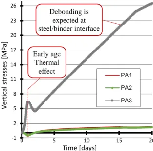
The simulations translate the heterogeneity in stress development in the structure. The model does not take into consideration the debonding between binder and steel container. Therefore, results at the interface binder/steel (at the point PA3) are not reliable for mechanical analysis. Evolution of radial stresses given in figure 12 justifies the debonding assumption. Contact elements should be introduced in the model in order to simulate real behavior of such structures.
Figure 11: Internal vertical stresses evolution in a
massive activated slag mortar structure - Elastic model (signs convention: (-) compression, (+) tension).
Figure 12: Internal radial stresses evolution in a
massive activated slag mortar structure - Elastic model.
20 23 26 29 32 35 38 41 0 5 10 15 20 T e m p e ra tu re [ ˚C ] Time [days] PA1 PA2 PA3 0 0,1 0,2 0,3 0,4 0,5 0,6 0,7 0,8 0,9 1 0 5 10 15 20 D e g re e o f a d va n ce m e n t o f h yd ra ti o n r e a ct io n [ -] Time [days] -1 2 5 8 11 14 17 20 23 26 0 5 10 15 20 V e rt ic a l st re ss e s [M P a ] Time [days] PA1 PA2 PA3 -1 2 5 8 11 14 17 20 23 26 29 0 5 10 15 20 R a d ia l s tr e ss e s [M P a ] Time [days] PA1 PA2 PA3 Early age Thermal effect Debonding is expected at steel/binder interface
The effect of thermal strains is reproduced in the mechanical results. The higher rise in temperature in the center at very early age will induce an expansion that will be restricted by surface undergoing a lower rise. This will result in compression stresses in the center, traction stresses at the surface. At higher age, the tensile stresses generated by autogenous shrinkage strains restriction will be the most significant phenomenon.
Computation results obtained with Mazars damage model are only shown for analysis points PA1 and PA2 in figure 13. Reduction in developed stresses values is observed showing that localized debonding at steel/binder interface reduces the degree of restriction and thus generated stresses.
Figure 13: Internal stress evolution in a massive
activated slag mortar structure - Damage Model.
The mechanical modelling proved that the study of cracking risk in alkali-activated slag mortar massive structures needs to model in a relevant way the interface between the binder and the steel container.
3.2 Alkali-activated mortar with rigid inclusions
An inclusion having an elastic modulus of 44 GPa and Poisson ratio of 0.2 is considered. A volume fraction of 50% is used in the modelling.
The presence of rigid, dimensionally stable inclusions will generate tensile stresses in the binder by restraining autogenous shrinkage
strains. Therefore the mechanical impact of rigid inclusions should be studied.
Multi-scale modelling approach is thus relevant in this case of study. It provides upscaled material properties (thermal conductivity, Young modulus etc…) but also generated stresses by self-restraints (inclusion/binder).
3.2.1 Mesoscale homogenization
Different analytical models were developed in this research field. Some consider general ellipsoidal inclusions (Mori Tanaka, coherent and auto-coherent) [23-24] based on the model of Eshelby tensor, while others consider spherical inclusions (Hashin) [25].
The model developed by Leroy [22] was chosen as a first approach for simplicity. Analytical computation was conducted to determine the effect of rigid spherical inclusions on the equivalent shrinkage (binder + inclusion) and the internal stresses development.
The model is based on Hashin theory and takes into consideration inclusion compactness. The mechanical behavior is supposed to be elastic. The tensile Orto-radial stresses .cd generated in the mortar resulting from inclusion strains restriction are illustrated in figure14. Dark regions 1 and 3 represent the binder (mortar) while region 2 represents the inclusion (aggregate).
Figure 14: Stress generation due to spherical inclusion
internal restriction [22].
The model is detailed in the mentioned reference [22]. Application results are summarized in figures 15, 16 and 17.
The analytical results (figure 17) show that the mortar will not be damaged because of the
-0,2 0 0,2 0,4 0,6 0,8 1 1,2 0 5 10 15 20 V e rt ic a l st re ss e s [M P a ] Time [days] PA1 PA2
inclusions restriction during 20 days. In fact, the generated stresses due to shrinkage restriction are lower than the tensile strength calculated for the mortar matrix at early ages (20 days).
Figure 15: Young modulus calculated according to
Leroy.
Figure 16: shrinkage restriction caused by rigid
Inclusions according to Leroy.
Figure 17: Developed radial and tangential stresses in
the mortar matrix according to Leroy compared to tensile strength development.
Although these calculations give an idea on the stresses generated in the matrix, the developed model doesn’t take into account yet the
evolution of strains and elastic modulus in time. Therefore additional work should be carried out in order to determine more accurate relations of shrinkage restriction. Furthermore, the study should be extended in time in order to predict stresses development and cracking risks for long term behavior.
3.2.2 Macro-scale simulation
At this level, only thermo-chemical finite element simulations were conducted.
Density, volumetric calorific capacity and thermal conductivity (according to Mori-Tanaka model [23]) were calculated for the homogenized material. Additionally, the latent hydraulic heat was multiplied by the volumetric fraction of mortar present in the material Results are represented in figures 18 and 19.
Figure 18: Temperature evolution in a massive
activated slag mortar structure with 50% rigid inclusions.
Figure 19: Degree of advancement of hydration
reaction evolution in a massive activated slag mortar structure with 50% volume fraction of rigid inclusions.
0 10 20 30 40 50 0 5 10 15 20 E la st ic it y M o d u lu s [G P a ]
Equivalent time [days]
E (Inclusion) E (homogenezation) E (mortar) -250 -200 -150 -100 -50 0 0 5 10 15 20 A u to g e n o u s sh ri n ka g e [µ m /m ]
Equivalent Time [days]
Matrix shrinkage Restricted shrinkage 0 2 4 6 8 0 5 10 15 20 St re ss e s [M P a ]
Equivalent Time [days]
Mortar tensile strength Tangential stresses Radial Stresses 20 20,5 21 21,5 22 22,5 23 23,5 24 24,5 25 0 5 10 15 20 T e m p e ra tu re [ ˚C ] Time [days] 0 0,2 0,4 0,6 0,8 1 0 5 10 15 20 D e g re e o f a d va n ce m e n t o f h yd ra ti o n r e a ct io n [ -] Time [days]
They show the significant decrease in temperature rise due to hydration heat and complementary decrease in reaction kinetics. These observations underlines that autogenous shrinkage restraint is the main phenomenon in cracking.
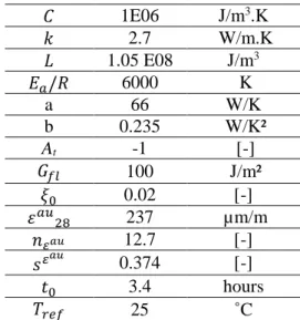
4 MODELLING PARAMETERS
Table 1: Modelling parameters recapitulation.
1E06 J/m3.K 2.7 W/m.K 1.05 E08 J/m3 / 6000 K a 66 W/K b 0.235 W/K² At -1 [-] fX) 100 J/m² A$ 0.02 [-] ' * DE 237 µm/m gHIJ 12.7 [-] NHIJ 0.374 [-] $ 3.4 hours (X 25 ˚C 5 CONCLUSIONS
This project allowed us to draw the following conclusions:
- Alkali activated slag binders exhibit exothermal hydration reactions with low heat release,
- Autogenous shrinkage strains of alkali activated slag binders are significantly high and evolve even after 100 days. This study should be continued with measurements of desiccation shrinkage, internal relative humidity and creep strains for further understanding of the material’s delayed deformations, - Experiments showed that the classical
thermo-chemo mechanical modelling used for OPC binders (based on quasi-adiabatic tests for parameters identification) is unsuitable for this type of binders. However, equivalent time modelling seemed to be adequate, - The transition between dynamic
elasticity modulus and static one (Young) for alkali-activated slag should
be addressed,
- Numerical simulations addressing a massive structure of the studied materials showed that developed stresses are mainly due to autogenous shrinkage strains than to thermal gradient in the material,
- Contact elements should be used at the binder/container interface in order to reproduce the debonding that would result from binder shrinkage. Experimental study of steel/slag mortar adhesion is necessary,
- In order to simulate cracking risks derived from rigid inclusions restrictions, further work on homogenization method taking into account evolution of mechanical properties, autogenous and basic creep strains with time is necessary. Furthermore, the transition from meso to macro scale stresses should be studied,
- Study the material’s tensile creep is also important to assess the relaxation of induced stresses at early age.
REFERENCES
[1] Zhang, Z., Yao, X. and Zhu, H. 2010. Potential application of geopolymers as protection coatings for marine concrete: II. Microstructure and anticorrosion mechanism. Applied Clay (49); pp. 7-12. [2] Malolepszy, J., Deja, J. and Brylicki, W.
1994. Industrial application of slag alkaline concrete. Proceedings of the first international conference on alkaline cements and concretes (2); pp. 989-1001.
Cited in [4]
[3] Scrivener, L., Kirkpatrick, J. 2008. Innovation in use and research on cementitious material. Cement and concrete research (38); pp. 128-136.
[4] Provis, J. and van Deventer, J. 2014. Alkali activated materials. (Eds) State of the art
report, RILEM TC224-AAM.
[5] Deja, J. 2002. Immobilization of Cr6+, Cd2+, Zn2+ and Pb2+ in alkali-activated slag binders. Cement and concrete research
(32); pp. 1971-1979.
[6] Shi, C. and Fernandez-Jimenez, A. 2006. Stabilization/solidification of hazardous and radioactive wastes with alkali-activated cements. Journal of hazardous
materials (B137); pp. 1656-1663.
[7] Cartwright, C, Rajabipour, F., Radli, A. and Building, S. 2014. Shrinkage characteristics of alkali-activated slag cements. Journal of materials in civil
engineering (27); pp. 1-9.
[8] lackner, R. and Mang, H.A. 2004. Chemo-plastic material model for the simulation of early age cracking: From the constitutive law to numerical analyses of massive concrete structures. Cement and concrete
composites (26); pp. 551-562.
[9] Ulm, F.J. and Coussy, O. 1998. Coupling in early-age concrete: From material modelling to structural design.
International journal of solids and structures (35); pp. 4295-4311.
[10] Shin, K.Y., Kim, S. B., Kim, J. H., Chung, M. and Jung, P. S. 2002. Thermo-physical properties and transient heat transfer of concrete at elevated temperatures.
Neuclear engineering and design (212);
pp. 233-241.
[11] Briffaut M., Benboudjema F., Torrenti J.-M. and Nahas G. 2011. Numerical analysis of the thermal active restrained shrinkage ring test to study the early age behavior of massive concrete structures, Engineering
Structures, 33 (4), pp. 1390-1401. International journal of solids and structures (35); pp. 4295-4311.
[12] Mazars, J., 1986. A description of micro and macroscale damage of concrete structures. Engineering Fracture Mechanics (25), 729-737.
[13] Pijaudier-Cabot, G., and Bažant, Z.P., 1987. Nonlocal damage theory. Journal of
Engineering Mechanics (113); pp
1512-1533.
[14] Cervera, M. and Chiumenti, M. 2006. Mesh objective tensile cracking via a local continuum damage model and a crack tracking technique. Computer methods in
applied mechanics and engineering (196);
pp 304-320.
[15] Rots, J.G., 1988. Computational modeling of concrete fracture. PhD Dissertation,
Delft University of Technology, Netherlands.
[16] Martinez, F. 1992. Experimental control of deformability at hsort-term loading in testing large-span pre-stressed structures.
Materials and structures (25); pp 231-238.
[17] Byfors J. 1980. Plain concrete at early ages.
Cement and concrete research institute.
[18] Collins, F. G. and Sanjayan, J. G. 1999. Workability and mechanical properties of alkali-activated slag concrete. Cement and
concrete research (29); pp 455-458.
[19] Hilaire A., Benboudjema F., Darquennes A., Berthaud Y. and Nahas G. 2014. Modeling basic creep in concrete at early-age under compressive and tensile loading,
Nuclear Engineering Design, (269); pp.
222-230
[20] Gebregziabiher, B. S., Thomas, R. and Peethamparan, S. 2015. Very early-age reaction kinetics and microstructural development in alkali-activated slag.
Cement and concrete composites (55); pp
91-102.
[21] Chen, W. 2007. Hydration of slag cement theory, modelling and application. PhD
Dissertation, University of Twente, Netherlands.
[22] Le Roy, R. 1995. Déformations instantanées et différées des bétons à hautes performances. PhD Dissertation,
Ecole Nationale des Ponts et Chaussées, France.
[23]Mori, T., Tanaka, K., 1973. Average stress in matrix and average elastic energy of materials with misfitting inclusions. Acta
Metallurgica (21); pp 571–574.
[24]Hill, R. 1965. A self-consistent mechanics of composite materials. Journal of
mechanics and physics of solids (13); pp
213–222.
[25]Hashin, Z., Shtrikman, S., 1963. A variational approach to the theory of the elastic behaviour of multiphase materials.
Journal of Mechanics and Physics of Solids