HAL Id: inria-00070205
https://hal.inria.fr/inria-00070205
Submitted on 19 May 2006HAL is a multi-disciplinary open access
archive for the deposit and dissemination of sci-entific research documents, whether they are pub-lished or not. The documents may come from teaching and research institutions in France or abroad, or from public or private research centers.
L’archive ouverte pluridisciplinaire HAL, est destinée au dépôt et à la diffusion de documents scientifiques de niveau recherche, publiés ou non, émanant des établissements d’enseignement et de recherche français ou étrangers, des laboratoires publics ou privés.
Hardware/Software Exploration for an Anti-collision
Radar System
Sébastien Le Beux, Vincent Gagné, El Mostapha Aboulhamid, Philippe
Marquet, Jean-Luc Dekeyser
To cite this version:
Sébastien Le Beux, Vincent Gagné, El Mostapha Aboulhamid, Philippe Marquet, Jean-Luc Dekeyser. Hardware/Software Exploration for an Anti-collision Radar System. [Research Report] RR-5820, INRIA. 2006, pp.15. �inria-00070205�
ISSN 0249-6399
ISRN INRIA/RR--5820--FR+ENG
a p p o r t
d e r e c h e r c h e
Thème COM
INSTITUT NATIONAL DE RECHERCHE EN INFORMATIQUE ET EN AUTOMATIQUE
Hardware/Software Exploration for an Anti-collision
Radar System
Sébastien Le Beux — Vincent Gagné — El Mostapha Aboulhamid — Philippe Marquet — Jean-Luc Dekeyser —
Email: {lebeux,marquet,dekeyser}@lifl.fr {gagnevi,aboulham}@iro.umontreal.ca
N° 5820
Unité de recherche INRIA Futurs Parc Club Orsay Université, ZAC des Vignes, 4, rue Jacques Monod, 91893 ORSAY Cedex (France)
Téléphone : +33 1 72 92 59 00 — Télécopie : +33 1 72 92 59 ??
Hardware/Software Exploration for an Anti-collision Radar System
Sébastien Le Beux , Vincent Gagné , El Mostapha Aboulhamid , Philippe Marquet ,Jean-Luc Dekeyser ,
Email:{lebeux,marquet,dekeyser}@lifl.fr {gagnevi,aboulham}@iro.umontreal.ca
Thème COM — Systèmes communicants Projet DaRT
Rapport de recherche n° 5820 — January 30, 2006 — 15 pages
Abstract: Anti-collision radars help prevent car accidents by detecting obstacles in front of vehicles
equipped with such systems. This task traditionally relies on a correlator, which searches for similari-ties between an emitted and a received wave. Other modules can then use the information produced by the correlator to compute the distance and the relative speed between the moving vehicle and the obstacle. We implemented such a system using FPGA. We used hardware blocks to implement the high demanding computing correlator and a soft-core processor to compute the distances and speeds. In order to improve the maximum detection distance reached by the correlation algorithm, we developed and tested a modified version of a Higher Order Statistics based algorithm. This work results in a detailed description of this new algorithm, its possible implementations and their FPGA synthesis results.
Exploration matérielle/logicielle d’un système de radar anti-collision
Résumé : Les radars anti-collision permettent la prévention d’accidents, via d’une détection des
obs-tacles se trouvant devant un véhicule utilisant ce dispositif. Cette tâche de détection d’obsobs-tacles est généralement réalisée à l’aide d’un corrélateur, mettant en évidence les points communs entre une onde émise et une onde reçue. D’autres modules peuvent ensuite calculer la distance et la vitesse relative entre la voiture en déplacement et l’objet détecté. Nous avons implémenté un tel système sur FPGA. Nous avons utilisé des blocs matériels pour implémenter le corrélateur, gourmand en res-sources de calculs, et un processeur soft-core pour traiter les calculs de distance et de vitesse. Dans le but d’augmenter la distance maximale de detection actuellement permise par l’algorithme de la corrélation, nous avons développé et testé une version modifiée d’un algorithme basé sur les statis-tiques d’ordres supérieurs. Il découle de ce travail une description détaillée de ce nouvel algorithme, ces possibles implémentations et les résulats de sa synthèse sur FPGA.
Hardware/Software Exploration for an Anti-collision Radar System 3
Introduction
Safety has become an important subject for car manufacturers. Some approaches target the safety of the passengers in a crash, while others try to anticipate them. Anticipating a delicate situation requires the knowledge of the exterior context. It is the case of anti-collision radars, which use radar waves to detect obstacles. An embedded anti-collision radar is a system which emits a wave (in our case: 76.5 GHz). When the emitted wave hits an obstacle (other vehicles, animals, etc.), it is re-emitted in the direction of the vehicle. The system compares the received wave with the re-emitted one, searching for similarities resulting from the presence of an obstacle in front of the car. Computing the time spent between the emission and the reception of the wave, the system can determine the distance between the car and the obstacle. By periodically computing this distance, the system can also estimate the relative speed of the car and the obstacle. Similarly, the system can determine the acceleration using two or more speed estimations.
Thus, detecting an obstacle comes down to one task: performing the correlation of an emitted and a received wave. A well-known correlation algorithm, described in Section 2, fails to satisfy certain constraints [3]: according to the characteristics of a certain radar, the maximum detection distance of such an algorithm is almost 100m in favorable conditions [5]. In this article, we propose a new algorithm, based on Tugnait’s work [10, 11], that increases the maximum detection distance. This algorithm is based on Higher Order Statistics formulation [10].
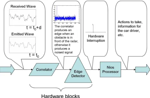
This obstacle detection is placed in an embedded system context, where resources are limited. This leads us to use FPGA technologies, which offer flexible solutions for the implementation of the modified Tugnait algorithm. Moreover, FPGAs allow us to implement a complete system, where intensive signal processing tasks are implemented as hardware blocks and sequential computations (distance, speed, etc.) are performed on a soft-core processor (see Figure 1).
Figure 1: Schematic view of the obstacle detection system on FPGA
The paper is organized as follows: Section 1 justifies the need for a new anti-collision radar algo-rithm. Section 2 presents a well-known correlation algorithm and its FPGA implementations. From that, we extract simple mathematical formulas estimating the amount of resources needed for their implementation on a FPGA. The same formulas are used to estimate the number of resources taken by the modified Tugnait algorithm, presented in Section 3. Section 4 describes the software tasks
4 Sébastien Le Beux, Vincent Gagné, El Mostapha Aboulhamid, Philippe Marquet, Jean-Luc Dekeyser
performed by the Nios processor. Section 5 presents a basic visual validation of the whole system. Finally, Section 6 concludes this work.
1 Motivation and justification
A well-known detection algorithm, presented in Section 2, allows the detection of an obstacle located at 100m or less in front of the radar. Increasing the algorithm’s signal-to-noise ratio (SNR) is equiva-lent to increasing its maximum detection distance. This in turn helps to better anticipate a collision. Several solutions exist to enhance the SNR:
• Increasing the power of the emitted wave: This is probably the simplest solution to improve the SNR observed in the received wave. However, power constraints (often present in the embedded world) limit the use of this solution.
• Increasing the sample resolution of the received wave: Received waves collected by the radar (analog) are converted into a digital form. According to the precision of the converter, the dig-ital signal can be encoded using 12, 16 or more bits. Using a high resolution seems to be an efficient way of increasing the performance of the global detection algorithm. However, previ-ous studies [5] have shown that using 4 MSB bits to encode the received signal is an optimal solution, since other bits mainly contain noised information and consume more computation resources.
• Increasing the length of the reference code: It increases the precision of the system. How-ever, each time the code’s length is doubled, the computation complexity and the number of resources used are also doubled [8].
• Changing the detection algorithm: Changing the correlation algorithm to a more powerful one should increase the maximum obstacle detection distance. We decided to implement a modified version of the third Higher Order Statistic algorithm [10, 11]. We aim to increase the SNR, and in doing so increase the maximum detection distance. Other algorithms [1, 4, 12] that propose to reduce the noise within the emitted signal may be considered in the future.
2 Correlation algorithm
Detecting an obstacle is possible thanks to the comparison between the received wave and the emit-ted one. A common correlation algorithm [2] performs this comparison. In this section, we give three views of this algorithm: mathematical, software and hardware.
2.1 Mathematical Formulation
A mathematical formulation of the correlation algorithm is given by: Ccy(j) = 1 N N −1 X i=0 c(i) · y(i) (1)
• N: The number of samples in the reference code. In our case, we fix N to 1023 based on previous work [5].
• c: The reference code [7] used to create the emitted wave (to be more precise, the radar signal is modulated with a reference code, and is continuously emitted) generated by a Linear Feedback Shift Registers [6]. Each sample of c is encoded using 1 bit: =
(
1 if c=010
−1 else
Hardware/Software Exploration for an Anti-collision Radar System 5
while (1) {
OutCorrelation = 0; y[0] = *ReceivedSignal; for(i=0; i<1022; i++) {
y[i+1] = y[i]; }
for(i=0; i<1023; i++) {
OutCorrelation += c[i] * y[i]; }
EdgeDetection(OutCorrelation); }
Figure 2: A C implementation of the correlation algorithm
• y: The received wave (only noise if there is no obstacle, reference code attenuated with noise if there is one). Each sample of y is encoded using 4 bits (previous studies have shown that it is a good trade-off between precision and resources used) and is used N times [5].
The 1
N factor normalizes the results. We do not take into account this factor while implementing
the algorithm. Thus, a reduced formula is: Ccy(j) = 1022 X i=0 c(i) · y(i) (2) 2.2 Software Implementation
A software implementation of the correlation algorithm given in formula 2 is immediate. Figure 2 contains such an implementation in C.
When using an AMD processor (32 bits, 1200 MHz, 256 kB cache size, 1 GB RAM memory), the maximum runtime frequency is approximately 63 kHz. Using another AMD processor (64 bits, 2200 MHz, 512 kB cache size, 2 GB RAM memory), we obtain a maximum runtime frequency of 122 kHz. Those results are far away from the required frequency, which is 100 MHz.
In a software implementation, operations are mainly done in a sequential way, explaining the obtained results. Using a multiprocessor architecture would enhance the maximum frequency of the application. Moreover, since operations use 32-bit integers, the software implementation is poten-tially more precise than the FPGA implementation (which uses 4 bits to encode y[i]). However, the code given in Figure 2 is highly parallelizable, suggesting that a hardware implementation would give better results.
2.3 Hardware Implementation
When implementing the correlation algorithm 2 on a FPGA, one needs to understand how its design choices will affect the performance of the resulting circuit. The objective of this section is to clearly define which kind of implementation is efficient and which one is not. Therefore, we synthesized each one of the proposed implementations.
Moreover, in order to re-use the synthesis work done in this section, mathematical formulas es-timating the number of resources used by any given implementation were developed (estimations are precise when the target FPGA is an Altera Stratix board; if not the case, some modifications are
6 Sébastien Le Beux, Vincent Gagné, El Mostapha Aboulhamid, Philippe Marquet, Jean-Luc Dekeyser
needed to take into account the target’s characteristics). The formulas shall allow us, in Section 4 and in future works, to easily estimate the impact of future hardware implementations on FPGA.
The formula 2 can be decomposed into three steps: shift registers, multiplication and addition. Shift registers: In the correlation algorithm 2, each received wave sample is used 1023 times. Since we need to compare the last 1023 received samples with the reference (which is fixed), each newly received sample is sent to a shift register, as shown in Figure 3.
EShif tRegisters= N · n (3)
E represents the estimated number of resources used and n represents the number of bits used to encode each received sample. In our case, n = 4 and N = 1023.
Ccy y received wave c reference code
y(i) "0001" −1 1 −1 c(i) y(i).c(i) Systolic topology Tree topology Ccy Ccy
Figure 3: Schematic view of the hardware implementation of the correlation algorithm Multiplication: 1023 multipliers are required to perform the global summation. They are inde-pendent and thus, can be done in parallel.
ESimpleM ultiplication= N · n (4)
Addition: The addition step performs the summation of all 1023 products coming from the mul-tiplication step. Since all 1023 products are 4-bit words, results are coded using 14 bits. There are two main hardware implementations for a summation:
• Tree topology • Systolic topology
Hardware/Software Exploration for an Anti-collision Radar System 7
2.3.1 Tree Topology
A well-known solution to implement a summation is the tree topology. To allow better segmentation of the addition tree (which has 1023 inputs), a neutral value is added. Thus, the addition tree has 1024 values and can easily be decomposed (see Figure 4). The critical path of this structure is equiv-alent to crossing one addition of each stage. However, this topology enables the use of registers to pipeline the additions. When adding a register between each stage, the critical path becomes equal to the longest path between two stages. The maximum obtained frequency then depends on the last addition (the 14-bit addition). Other solutions can be employed to reduce the latency of the global summation without decreasing the maximum reached frequency. Since we do not really care about latency, we do not elaborate on this subject.
Formula 5 estimates the number of FPGA resources required for the implementation of the tree.
EAdditionT ree= N · (n + 2) − log2(N ) − n − 2 (5)
In order to use fewer resources, it is possible to perform averages instead of additions. It results in a reduction of the system’s precision. For example, if a full average is performed on 1023 4-bit input values, then the output will be encoded using 4 bits. In comparison, the output would be encoded using 14 bits when performing a normal summation. The impact on the output precision shall be evaluated in order to choose between the two solutions. Of course, an intermediate solution (using both additions and averages) can be used.
Formula 6 estimates the number of resources used when performing averages.
EAverageT ree = (N − 1) · (n + 1) (6)
2.3.2 Systolic Topology
The systolic topology is another well-known structure. According to [9], the implementation of such algorithms is efficient on FPGAs. Thus, in order to validate/invalidate those assumptions, we de-cided to implement it. When implementing the pipeline solution, many cells are only used for their 1-bit register. When not pipelining the additions, all of them need to be done in one cycle. This means that the critical path becomes equivalent to crossing all additions (1022). Thus, the maximum obtained frequency is very low.
The estimation formulas can be expressed by:
EAdditionSystolic = N · (log2(N ) + n − 1) − n + 1 (7)
EAdditionSystolicP ipeline = 2 · EAdditionSystolic (8)
Similarly to the tree topology, the systolic topology can perform averages instead of additions. The formulas become:
EAverageSystolic= (N − 1) · (n + 1) (9)
EAverageSystolicP ipeline= (N − 1) · (2 · n + 1) (10)
8 Sébastien Le Beux, Vincent Gagné, El Mostapha Aboulhamid, Philippe Marquet, Jean-Luc Dekeyser
Implementation details Max. frequencies Used Resources (in MHz) Synthesis Estimations
Addition Tree Full pipeline 229 14 362 14 312
One cycle 45 11 873 14 312
Systolic Full pipeline 151 36 736 34 802
One cycle 5,5 12 957 21 493
Average Tree Full pipeline 232 13 296 13 299
One cycle 49 10 718 13 299
Systolic Full pipeline 180 15 538 17 391
One cycle 0.61 11 761 13 299
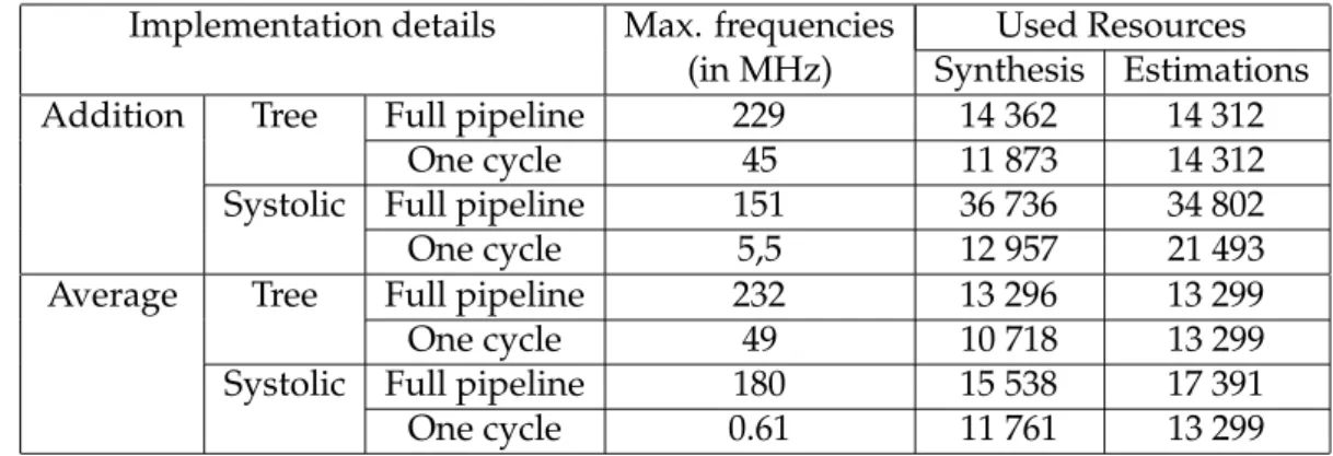
Table 1: Synthesis and estimation results for the correlation algorithm on a Stratix pro board 2.4 Comparison and Summary
Using the formulas 1 to 9 and synthesis results, we created Table 1, summarizing the synthesis and estimation results of different correlation algorithm implementations. The estimations errors do not exceed 20%, except for the addition, systolic one cycle solution. Indeed, this solution can be highly optimized by the FPGA manufacturers’ tools. Examining Table 1, we find that the tree topology is the most efficient implementation in both addition and average cases. It is the solution that allows for the most compact implementation among those reaching the required 100 MHz frequency. The tree topology shall be used in more complex algorithm implementations.
The synthesis results shown in Table 1 were obtained using an Altera Stratix pro. When syn-thesizing the algorithms for a Xilinx board, the results may be different (lower) due to availabil-ity/efficiency of logic cells to compute more complex fine grained operations.
3 Modified Tugnait Algorithm
In this section, we present and implement a new algorithm, based on Tugnait’s research [10, 11]. The objective of this new algorithm is double: increasing both the maximum obstacle detection distance and the SNR.
3.1 Mathematical Formulation
The mathematical formulation of the Higher Order Statistics (HOS) [10] algorithm is given by: J32(i0) = N −1 X j=0 " 1 N N −1 X i=0
y(i) · c(i + 1) · c(i + j)
# · " 1 N N −1 X i=0
y(i) · c(i + 1) · y(i + j + io)
#
(11) Just like the correlation, we are not interested by the normalization. Thus, the implemented algo-rithm is:
J32(i0) = N −1
X
j=0
Cycc(j) · Cycy(j + i0) (12)
Cycc= N −1
X
i=0
y(i) · c(i + 1) · c(i + j) (13)
Cycy = N −1
X
i=0
y(i) · c(i + 1) · y(i + j) (14)
Hardware/Software Exploration for an Anti-collision Radar System 9
• y: Received wave • c: Reference code
• N: Length of reference, = 1023
J3,2(io) is a correlation. Since the two entry points of this correlation are themselves results of previous correlations, we can expect the synthesis to produce a much larger design.
Three elements are required to compute Cycc: y(i), c(i+1), c(i+j). The last two are coded using 1 bit, and can easily be implemented by a multiplexer. The last one, y(i), uses 4 bits. Cycc computation is similar to the Ccy one.
Cycy structure is similar to the Cycc one. However, its implementation is much more complex. The difference is that y(i+j) is needed. Since y(i + j) is a previous value of the input signal (encoded using 4 bits, as opposed to the 1-bit encoding of c(i + j)), synthesizing this part of the algorithm requires more resources than synthesizing Cycc.
The evaluation of y(i) · c(i + 1) is needed to compute both Cycc(j) and Cycy(j). To optimize the implementation, its evaluation is done only once and then sent to both modules:
s(i) = y(i) · c(i + 1) (15)
s Cycy Cycc J3,2 J Detection Reference code Received wave c y
Figure 4: Schematic view of the modified Tugnait algorithm Figure 4 shows the schematic view of our hardware implementation of formula 11. 3.2 Comparison with the Correlation Algorithm
According to the mathematical formulations of both correlation and HOS algorithms, we can eval-uate their differences from a computation point of view. In order to facilitate the comparison, we choose to use an input wave composed of integers ranging from -7 to 7. Moreover, after analyzing the results presented in Table 1, we chose the pipelined tree solution performing additions as the reference correlation algorithm. Results are shown in Table 2.
3.3 Software Implementation
We implemented the algorithm described in formula 11 using the C language:
The resulting frequencies are 13 kHz for the 1200 MHz AMD processor and 32 kHz for the 2200 MHz 64-bit AMD processor.
10 Sébastien Le Beux, Vincent Gagné, El Mostapha Aboulhamid, Philippe Marquet, Jean-Luc Dekeyser
While(1) { J32 = 0;
y[0] = *ReceivedSignal; for(i=0; i<1022; i++) {
y[i+1] = y[i]; }
for(i=0; i<1023; i++) { s = y[i] * c[i+1]; Cycc[io] += s * c[i+io]; Cycy[io] += s * y[i+io]; } for(j=0; j<1023; j++) { J32 += (Cycc[j] * Cycy[(j+io) % 1023]); } io = (io+1) % 1023; } 3.4 Hardware Implementation 3.4.1 Full Version
The hardware implementation of the HOS algorithm requires much more resource than the correla-tion one.
One of the main reasons is the complexity increase in the multiplications. In the correlation al-gorithm, they are simple since one of the operands is a single-bit encoded element, while the HOS algorithm requires 1023 multiplications of two 4-bit operands and 1023 multiplications of a 15-bit operand by a 19-bit operand. DSP blocks can be used to implement some of the multiplications, but not all of them.
Another reason for the resource increase is the higher number of registers needed by the modified Tugnait algorithm.
The computations of Cycy and J3, 2 elements require y(i + j) and Cycy(j + io). Therefore, we cannot use shift registers to store the values of y(i + j) and Cycy(j + io). In order to limit the number of connections (a full point-to-point connection would require 1023 exp 2 4-bit connections), the ob-jective is to immediately put the received sample in the right place. Each received sample in y(i + j) is used 1022 times. Looking at the algorithm, we find that they can be loaded inside the array y(i + j) cyclically, using enabled latches and a time base counter. Thus, since one part of the correlator uses shift registers and the other uses the counter solution, an efficient correlation is realized. This solu-tion seems to be the best one for the targeted FPGA family. Figure 5 shows a described view of the hardware implementation of formula 11.
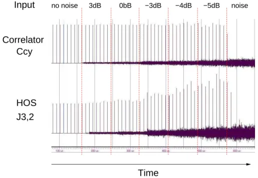
Simulations allow us to quickly evaluate the system’s behavior. Figure 6 compares the two al-gorithms. In order to simulate the radar’s inputs, we have created an input signal identical to the reference code, but attenuated with noise. The noise function used is based on classical Gaussian form, and does not produce noise like the one encountered in real conditions (on road) [10], for which the mathematical form is unknown. Thus, we can expect that the simulation results will be worst than real conditions ones. Reference code and noise are cyclically emitted, as in real conditions. This fact explains the edges on the output sides, which mean that an object has been detected.
Hardware/Software Exploration for an Anti-collision Radar System 11
Algorithm Formula Computation required Estimations Total
Correlation 2 shift y(i) 4 092 14 312
1 023 4-bits multiplications 4 092 14-bit summation of 1 023 elements 6 128
HOS 15 shift y(i) 4 092 8 184 378 480
1 023 4-bits multiplications 4 092
13 shift c(i + j) 1 023 11 243
1023 4-bits multiplications 4 092 14-bit summation of 1 023 elements 6 128
14 route y(i + j) 4 092 33 749
1023 8-bits multiplications 19 437 18-bit summation of 1023 elements 10 220
12 route Cycy(j + i0) 18 414 325 304
shift Cycc(j) 14 322
1023 32-bits multiplications 257 796 42-bit summation of 1023 elements 34 772
Table 2: Comparison between the correlation and the modified Tugnait algorithms
As expected, the output noise generated by the modified Tugnait solution is higher than the correlator’s one. However, the modified Tugnait solution produces higher edges when used in a high noised environment, showing a performance improvement over the correlator solution.
4 4 8 4 32 42 J3,2
Latch Latch Latch
Counter(mod 1023) Cycy
Counter(mod 1023)
Latch Latch Latch Latch Latch
y received wave
c(i+1) reference code s(i)
c(i+j) reference code
18 Cycc 14 y(i+j) y(i) Cycc(j) Cycy(j+i0)
Figure 5: Schematic view of the modified Tugnait algorithm hardware implementation
3.4.2 Reduced Version
The full version of the algorithm, with no reduction, requires at least 375 000 logical cells. The Altera board we are targeting is a Stratix pro edition, which contains 40 000 logical cells. The full circuit
12 Sébastien Le Beux, Vincent Gagné, El Mostapha Aboulhamid, Philippe Marquet, Jean-Luc Dekeyser
cannot be implemented on it. In that version, the inputs are encoded using 4 bits and the results use 44 bits. However, many optimizations are possible, and allow a reduced algorithm implementation on the target FPGA, with a performance reduction.
Two optimizations are performed:
• The first uses the average version rather than the addition one; • The second reduces the sample resolution of the inputs.
Using the formulas developed in Section 2, we can easily estimate the number of resources required for any given implementation. Results are given in Table 2. According to it, the target FPGA (Stratix pro containing 40 000 logical cells) only supports the last solution, which uses the average method-ology and receives signals comprised between -1 and 1. Still, various tests run on the implemented reduced FPGA version proved its validity.
In this section, we have presented a modified Tugnait algorithm. From its mathematical formu-lation, we have made a software implementation, and a hardware one. According to simuformu-lation, we have validated the algorithm’s behavior and, based on the results given in the correlation algorithm section, we have chosen the right solution and implemented it on the target FPGA.
HOS
Time
J3,2
Correlator
Ccy
no noiseInput
3dB 0bB −3dB −4dB −5dB noiseFigure 6: Simulation results comparing both algorithms
4 Software Tasks
The algorithms presented in the previous sections produce a signal in which an edge is generated whenever an obstacle is detected. According to this detection, distances and speeds can be computed in a sequential way. A soft-core processor and a C program are efficient enough to do that work.
Three elements are needed to compute the distance:
• an edge detection module, which generates interruptions on the processor; • a counter, which computes the wave course time;
Hardware/Software Exploration for an Anti-collision Radar System 13
Implementation choice Number of logical cells Possible target Correlator addition −7 ≥ y ≥ 7 14 312 Stratix II EP2S30
Tugnait addition −7 ≥ y ≥ 7 375 000 none
Tugnait average −7 ≥ y ≥ 7 150 000 Stratix II EP2S180 Tugnait average −3 ≥ y ≥ 3 100 000 Stratix II EP2S130 Tugnait average −1 ≥ y ≥ 1 32 000 Stratix II EP2S60
Table 3: Estimation results for the modified Tugnait algorithm
//Radar is a structure composed of NB_AVERAGE_DISTANCE //variables, holding the last computed average distances while(1) {
if(EdgeDetection) { NbEdges++;
DistanceTemp += *Counter;
//*Counter is directly proportional to the obstacle distance }
if(RadarPositionChange) {
for(i=NB_AVERAGE_DISTANCE; i>0; i--) Radar[PreviousPosition].distances[i] = Radar[PreviousPosition].distances[i-1]; if (NbEdges != 0) Radar[PreviousPosition].distances[0] = DistanceTemp/NbEdges; else Radar[PreviousPosition].distances[0] = NEUTRAL_VALUE; DistanceTemp = 0; NbEdges = 0; PreviousPosition = *RadarPosition; } }
Figure 7: Distance computation
• the radar direction, creating a 2-dimensional view of the context in front of the vehicle equipped with the radar.
Interrupts are used to detect both edges and radar orientation changes. For each position, edges and their associated distances are stored in memory. When the radar position changes, an average distance, based on previously stored data, is computed. The following code (we omitted the inter-rupts handlers’ details) performs these actions:
In this section, we showed that we are able to use a processor to analyze the outputs of the algorithms presented in sections 2 and 3 and to anticipate a collision.
5 First Experimental Validation
A full validation of the anti-collision algorithm and the complete system, including the soft-core, needs precise and long tests. However, in order to get a first approximation, we have connected a VGA monitor to the FPGA. This monitor gives a first useful view of the application behavior.
14 Sébastien Le Beux, Vincent Gagné, El Mostapha Aboulhamid, Philippe Marquet, Jean-Luc Dekeyser
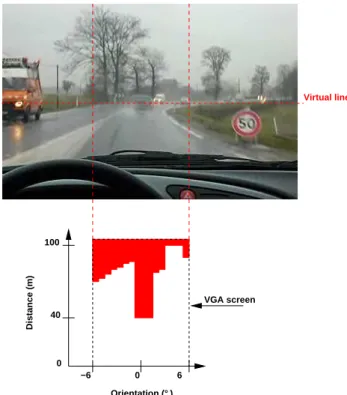
When an emulated object is detected, according to the algorithm describe in section 3, the proces-sor stores relevant data and compute distance as described by the algorithm of the figure 7. These distance informations are written to output VGA screen and are directly associated to the radar orien-tation. Sixteen different orientation of the radar are possible and the distance is the only information reported on the screen.
0 Orientation (°) 6 −6 Distance (m) 0 100 40 Virtual line VGA screen
Figure 8: VGA output screen
The figure 8 shows an example of what is expected in real conditions tests. For that test, a radar emulator generate a received wave y according to the picture shown on the top of the figure. On the bottom of the figure, all objects placed on the virtual line at a maximum of 100 meters are detected. On the screen output, the column comprise between -1° and 2° corresponds to the car on the road in front of the system detection. Others details appears, like the car place on the orientation limit of the radar.
The basic exploitation of the whole system including the hardware and the software modules in this visualization on a VGA screen allows to partially validate behavior of the global system.
6 Conclusion
A way to increase the sensibility of an anti-collision detection system is to change the algorithm in charge of the evaluation of the similarities between emitted and received waves. According to simu-lation, it has been shown that the algorithm based on Higher Order Statistics (HOS) computation is an efficient solution. For a well-known correlator algorithm, we analyzed several FPGA implementa-tions results. From those results, simple mathematical formulas estimating the resources needed by the FPGA were created. According to the estimations, we defined an efficient hardware implemen-tation of an efficient anti-collision algorithm. However, this algorithm requires too much resource for the target FPGA. A reduced version was then developed. We compared the several implementa-tions of this algorithm, in terms of FPGA needed resources and signal-to-noise ratio. The full system, based on a reduced version, was implemented on FPGA and coupled to a processor. The processor
Hardware/Software Exploration for an Anti-collision Radar System 15
is needed to compute the distance and the speed, and is independent of the chosen algorithm. We are planning on running simulations using real conditions to test HOS algorithm. However, our ex-perimentations allowed us to estimate that a reduced algorithm could be implemented on a FPGA containing 130 000 basics cells. Real test conditions shall allow us to determine the maximum detec-tion distance offered by the implemented algorithm.
Acknowledgment
We would like to acknowledge J. Zaidouni and A. Menhaj-Rivencq, from the University of Valenci-ennes, for the fruitful discussions covering the correlation algorithm. M. Le Beux was supported by ModEasy, an Interreg III A project.
References
[1] R. Pan C. L. Nikias. Time delay estimation in unknown gaussian spatially correlated noise. In
IEEE trans. on acoustics, speech and signal processing, volume 36, nov 1988.
[2] Byron Edde.Radar Principles, Technology, Applications. Prentice Hall, September 1992.
[3] B. Fremont, A. Menhaj, P. Deloof, and M. Heddebaut. A cooperative collision avoidance and communication system for railway transports. In3rd IEEE Conference on Intelligent Transportation Systems, October 2000.
[4] C. L. Nikias H. Chiang. A new method for adaptative time delay estimation for non-gaussian signals. InIEEE trans. on acoustics speech and signal processing, volume 38, pages 209–219,
Febru-ary 1990.
[5] Y. El Hillali. Etude et réalisation d’un système de communication et de localisation, basé sur les tech-niques d’étalement de spectre aux transports guidés. PhD thesis, University of Valenciennes, 2005.
[6] NASA. Linear feedback shift registers. Technical report, NASA, 2002. [7] W. Peterson and E. Weldon.Error-correcting codes. MIT press, 1972.
[8] D. V. Sarwate and M. B. Pursley. Crosscorrelation properties of pseudorandom and related sequences. Inproceedings of the IEEE, volume 68, pages 563–619, May 1980.
[9] Satnam Singh. The lava hardware description language. Technical report, LAVA, 1999.
[10] J.K. Tugnait. On time delay estimation with unknown spatially correlated gaussian noise using fourth-order cumulants and cross cumulants. InIEEE transaction on signal processing, volume 39,
pages 1258–1267, June 1991.
[11] J.K. Tugnait. Time delay estimation with unknown spatially correlated gaussian noise. InIEEE transaction on signal processing, volume 42, pages 549–558, feb 1993.
[12] M. Raghuveer W. Zhang. Nonparametric bispectrum-based time delay estimations for multiple sensor data. InIEEE transaction on signal processing, volume 39, pages 770–774, March 1991.
Unité de recherche INRIA Futurs Parc Club Orsay Université - ZAC des Vignes 4, rue Jacques Monod - 91893 ORSAY Cedex (France)
Unité de recherche INRIA Lorraine : LORIA, Technopôle de Nancy-Brabois - Campus scientifique 615, rue du Jardin Botanique - BP 101 - 54602 Villers-lès-Nancy Cedex (France)
Unité de recherche INRIA Rennes : IRISA, Campus universitaire de Beaulieu - 35042 Rennes Cedex (France) Unité de recherche INRIA Rhône-Alpes : 655, avenue de l’Europe - 38334 Montbonnot Saint-Ismier (France) Unité de recherche INRIA Rocquencourt : Domaine de Voluceau - Rocquencourt - BP 105 - 78153 Le Chesnay Cedex (France)
Unité de recherche INRIA Sophia Antipolis : 2004, route des Lucioles - BP 93 - 06902 Sophia Antipolis Cedex (France)
Éditeur
INRIA - Domaine de Voluceau - Rocquencourt, BP 105 - 78153 Le Chesnay Cedex (France)
http://www.inria.fr