Publisher’s version / Version de l'éditeur:
ASHRAE Transactions, 65, pp. 551-570, 1960-07-01
READ THESE TERMS AND CONDITIONS CAREFULLY BEFORE USING THIS WEBSITE.
https://nrc-publications.canada.ca/eng/copyright
Vous avez des questions? Nous pouvons vous aider. Pour communiquer directement avec un auteur, consultez la
première page de la revue dans laquelle son article a été publié afin de trouver ses coordonnées. Si vous n’arrivez pas à les repérer, communiquez avec nous à [email protected].
Questions? Contact the NRC Publications Archive team at
[email protected]. If you wish to email the authors directly, please see the first page of the publication for their contact information.
NRC Publications Archive
Archives des publications du CNRC
This publication could be one of several versions: author’s original, accepted manuscript or the publisher’s version. / La version de cette publication peut être l’une des suivantes : la version prépublication de l’auteur, la version acceptée du manuscrit ou la version de l’éditeur.
Access and use of this website and the material on it are subject to the Terms and Conditions set forth at
Condensation between the panes of double windows
Wilson, A. G.; Nowak, E. S.
https://publications-cnrc.canada.ca/fra/droits
L’accès à ce site Web et l’utilisation de son contenu sont assujettis aux conditions présentées dans le site LISEZ CES CONDITIONS ATTENTIVEMENT AVANT D’UTILISER CE SITE WEB.
NRC Publications Record / Notice d'Archives des publications de CNRC:
https://nrc-publications.canada.ca/eng/view/object/?id=eadb4bdc-f2ee-4e83-958a-3c47244823d8
https://publications-cnrc.canada.ca/fra/voir/objet/?id=eadb4bdc-f2ee-4e83-958a-3c47244823d8
Ser
TH1
N2lr
2
no.
100
c. 2
BLDG
NATIONAL
RESEARCH
COUNCIL
C A N A D A
DIVISION OF BUILDING RESEARCH
CONDENSATION BETWEEN THE PANES O F DOUBLE WINDOWS
BY
A. GRANT WILSON AND E. S. NOWAK
REPRINTED FROM A M E R I C A N S O C I E T Y O F H E A T I N G . R E F R I G E R A T I N G P N D AIR - C O N D I T I O N I N G E N G I N E E R S T R A N S A C T I O N S . VOL. 65. 1959. P 551 - 570 RESEARCH PAPER NO 100 O F THE
- -
---? D 1 v l s l O N O F BUILDING R E S REsEP,RCI( ~ ~,
~ ~ ~ ~-
LIFl?/:!?Y
-I
I I PRICE 25 CENTSi
7. vnqq I .).. -' , . 'dI
OTTAWAI
1
i p q r ; O d s L ; I F S K . > . < C r cO:,h::ii)
J U L Y 1960 \.---
~~i NRC 5 4 2 0This p u b l i c a t i o n i s being d i s t r i b u t e d by t h e D i v i s i o n of Building Research of t h e National Research Council a s a c o n t r i b u t i o n towards b e t t e r
b u i l d i n g i n Canada.
I t
should not be reproducedi n whole o r i n p a r t , without permission of t h e
ori-
g i n a l publisher. The D i v i s i o n would be g l a d t o be
of a s s i s t a n c e i n o b t a i n i n g such permission.
P u b l i c a t i o n s of t h e D i v i s i o n of Building Research may be 0htaqne.1 h-7 - 0 4 1 4 q g t h e a p p r o p r i a t e
remittance, ( a
'
"0st
Off i c e MoneyOrder o r a chew
:
par i n Ottawa,t o t h e Receiver I, c r e d i t National
Research council; Research Council,
Ottawa. Stamps a, 2 . A coupon make payments f
c
Coupons a r e a v a i l and9
c e n t s , a n m i t t a n c e a s i n d i c ? used f o r t h e pur C o u n c i l p u b l i c a t i c t h e Canadian Gavel ? n introduced t o _&e l a t iv e l y s h p l e.
q.tions o f 5, 25, I by makinga
r e - s e couponsmay
be . a t i o n a l Research xpecifications of ions Board.Reprintedfrom
ASHRAE
TRANSACTIONS,
Vo1. 65, 1959
AMERICAN SOCIETY OF HEATING, REFRIGERATING AND AIR-CONDITIONING ENGINEERS, INC.
Copyright 1960
Printed in U.S.A.
No. 1685
CONDENSATION BETWEEN THE PANES
OF DOUBLE WINDOWST
T
HE VALUE of double windows in reducing heat transmission through windowareas and in permitting higher inside relative humidities during the winter, without excessi~e condensation on inside glass surfaces, is \\-ell known. Some form of cIouble-~\-indo~\~ arrangement is used in most houses in regions having low winter temperatures. 'I'hcre is a n increasing use of double \vindo\\rs in con~mercial and industrial buildings, particularly when year-round a i r conditioning is employed.
Condensation of water vapor between the panes, and on the inside surface of the outer pane, is a common occurrence with most types o f double windows except the factory-sealed variety. A small amount of such condensation is accepted generally a s inevitable. When it begins to obstruct seriously the view through the window for long periods, however, or when the run-off contributes t o the deterioration of surrounding materials, there is reason for concern.
Condensation will occur on the inside surface of the outer pane whenever the temperature of t h a t surface a t any point is below t h e dew-point temperature of the a i r - ~ a p o r mixture in the space between the panes. This ultimately \\ill occur, with outside temperatures laxer than inside, if the gain in water vapor to t h e space is greater than the loss.
In this paper the factors involved in the transfer of water vapor t o and from the space betv een the panes of double windows other than the factory-sealed t y p e are considerrd. A relatively simple approach is developed for determining under what conditions condensation will occur in a given window, or alternately, for designing a window to be free of condensation under given conditions.
\&later vapor generally moves in t o and o u t of the air space of a double window under two forces. It moves through the materials a n d cracks in the window assem-
t This paper is a contribution of the Division of Building Research, National Research Council of Canada and is published with the approval of the Director of t h e Division.
*
Head. Division of Building Research. National Research Council of Canada.*:k Division of Building Research. National Research Council of Canada.
Presented a t the Annual Meeting of t h e AMERICAN SOCIETY OF HEATING. REFRIGERATING A N D AIIL-
CONDITIONING ENGINEERS, Lake Placid. New York, June 1959.
NRC 5420
ASHRAE T R A N ~ A C T I O X ~
bly by diffusion a s a result of differences in partial pressure of the water vapor, a n d
.
i t is transferred a s a component of the air which flows through the craclrs in t h e assembly under total air pressure differences.Most of the materials used in window construction are relatively impermeable t o vapor, except wood and i t can be made relatively resistant through painting. T h e . craclrs and openings in the assembly will thus usually provide the major paths for vapor flow by diffusion. T h e permeability coefficient for air water-vapor mixtures is independent of relative humidity but does vary somewhat with temperature. For purposes of this discussion, however, i t can be assunled constant. The vapor flow by diffusion in to and o u t of the air space is then directly proportional to t h e pressure difference across inner a n d outer panes.
The vapor pressure differences across inner a n d outer panes are dependent o n inside and outside temperatures and relative humidities. Table 1 illustrates t h e possible order of these pressure differences. The values have been calculated t a k - ing inside room and air-space vapor pressures corresponding t o saturation a t t h e temperatures of the inner surfaces of the inner and outer panes respectively. Out- side vapor pressures were taken to correspond to saturation a t the outside air tem- perature. Surface temperatures were calculated for an inside air temperature of 70 F assuming an overall U value for the window of 0.53 a n d inside and outside
surface conductances of 1.5 and 6.6 respecti1 ely (based on heat transmission values for winclolvs in TIIE GUIDE 1958 of ASHAE).
The m p o r pressure difference across the inner pane is se\ era1 times greater than the l7apor pressure difference across the outer pane in all cases, the ratio of these pressure differences increasing with decreasing outside ten~perature. Thus, to ~naintain outflow equal to inflow, the effective resistance of the inncr glazing t o vapor flow by diffusion must be many times that of the outer glazing.
Se~reral factors may contribute t o total pressure differences across windows. \I ind is one commonly recognized. Air moTtn1ent around a structure nil1 result in a pattern of pressures t h a t depencls on man). lactors. Information on t h e actual pressures around buildings is relatively sparse. I t can be assumed in the si~nplest cases t h a t the pressures on leenard n.alls are below barometric n-hile those o n wind- n a r d walls are above it. Pressures inside the building resulting from mind action will depend on the distribution o f air leakage throughout the building enclosure. If the leakage characteristics of all exposures are similar, the pressures inside mill probably be less than barometric. As a basis for discussion, pressures on t h e nind- ward side, Icel~ard side, and inside o l 0.8, minus 0.5 and m i n ~ i s 0.2 \.elocity heads respectively can be assuiued. This leacls t o total pressure differences ol 1.0 vclocity head across windward windons and 0.3 velocity head across l e e ~ a r d windoi\-s.
5 5 1 ASI-IRAE TR.ZNS.\CTIONS
O U T S I D E
)
,--
A I R S P A C EPRESSURE PRESSURE PRESSURE
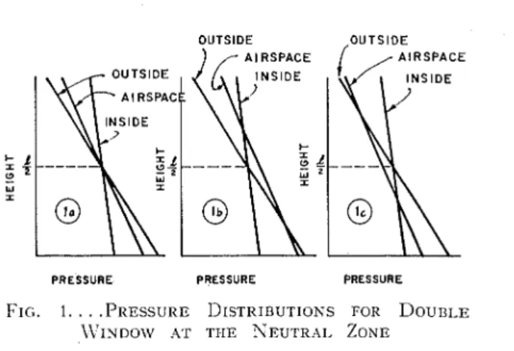
FIG. I . . . .PRESSURE DISTRIBUTIONS FOR D o u n ~ . ~
\\'INDO\V A T T I I E ~ E U T R A I , ZONE
For purposes of heat loss calculations, t h e flow from outside to inside resulting from the higher pressure difference is significant. I t is the flow from inside t o out- side occurring under the lower total pressure clifference, however, t h a t is significant in connection with condensation between double windows, since this results in a n e t gain in water vapor t o the air space. Table 2 illustrates the possible order of the pressure differences across leeward windows a s a result of wind action, based on 0.3
velocity head and a n air density of 0.075 Ib per cu ft.
A second major factor contributing to total pressure differences across windows is chimney action between air in a building and the outside induced by temperature differences. As a result, air tends t o flow into the building through lower openings ancl leave through upper openings. With no other forces acting, there is a neutral zone somewhere between a t which inside and outside pressures a r e equal. T h e pressure difference across the walls of any enclosed space due t o chirnney action can be calculated easily providing the temperature differences and the level of the neu- tral zone a r e known. Unfortunately, information on neutral zone locations for both residential ancl commercial buildings is estreinely limited.
Available csperin~ental I-ccords for residences1 suggest t h a t the actual levels arc considerably highcr than \voulcl bc predicted on thc basis of thc vertical distribution of \vindou.ancl door cracks. In single-story houses, the neutral zone may be above first floor windows, while in two-story houses it may be a t the level of second story mindo\vs. Recently published information on pressure differences across entrances
23 VENT HOLES DIA SPACED APPROX I'/; APAR
o o o o o o o o o o o o 6 o / o o o o ) 0 o o o o - A OUTSIDE
n
ALUMINUM CLIPS HOLDING INNER t~ GLAZING u ALUMINUM)
FRAMEI;'
LRUBBER GASKET INSIDE-
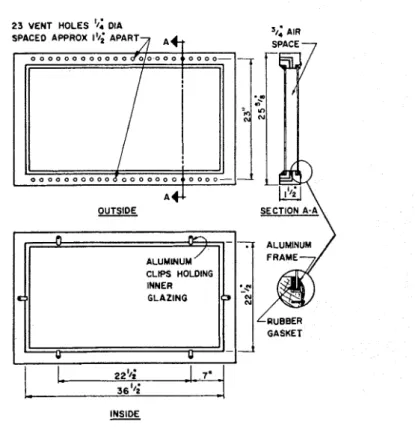
FIG. 3 . . . .DETAILS OF CENTER \ T 7 1 ~ ~ o \ v
of tall buildings suggests t h a t t h e neutral zone location in such structures may be well above mid-height.'
Since flow from the building t o outside occurs only above the neutral zone, the l e ~ e l ol the neutral zone is significant in connection with condensation between the panes, windo~vs above the neutral zonc being much more likely to eshibit such con- densation. Any factor tending t o raise the neutral zone, such a s venting or
mechanical exhaust s j stcms, \\.ill rccluce thc possibilitj of \\-indo\\? condensation ;
ally factor tcndillg to Ion-er the Ic\.el of thc neutral zonc, such as pressurizing o l buildings, will have the opposite effect.
The order ol the inside-outsicle pressure differences resulting Irom chimnej effect can be seen in Table 3 which gives pressurc differences per ft of distance froin the
556 ASHRAE TRANS~ZCTIONS
neutral zone a t different outside temperatures. T h e values a r e based on inside air a t 70 F with a density of 0.075 Ib per cu ft.
In double windows the resistance to air flow of the passages leading from inside the building t o t h e air space may be different from t h a t of the passages leading from
thc air space to outside t h c building. T h i s is not sigllificant with respect to heat loss, where overall leakage values are important. T h e rclativc air leakage charac- teristics of passages in to and o u t of the air space ]nay be highly significant, Ilonr- ever, with respect to condensation between panes. This is apparent when the dis- tribution of total pressures and resulting air flo~vs across double windows a r e 9
considered.
Fig. 1 illustrates the variations in pressure with height across a double window, subjected t o a temperature gradient where the neutral zone occurs a t mid-height. In representing the relative slopes of the pressure distribution curves, i t uras assumed I t h a t the temperature of the air space was closer t o outside temperature than to t h a t inside. T h e pressure distributions shown in Fig. l a will result whenever the resist- ance to flow above and below t h e neutral zone, around either or both panes, is equal. For example, this will occur with t h e passages uniformly distributed around the periphery of one or both panes.
Under these circu~ustances the air-space pressure is between inside and outside pressures a t all levels. Thus, inside pressure is higher than air-space pressure above
tlie neutral zone ancl l o ~ ~ e r below the neutral Lone. Similarly, the air-space pres- sure is higher than the outside pressure abo1.e tlie neutral zone and lower belom the neutral zone.
T h e air flow resulting from these pressure distributio~is will depend on t h e loca- tions and resistances of the passages. Flow will v a n from zero through passages located a t the ne~rtral zone to a ~naxirnum through pacsages a t the top and bottom of the wintlov. 'I'he air space can interchange air ~vitli 110th the inside and outside; the relati1.e amounts depend on the relati] e resistance t o do\\ of I he passages. If the inside of tlie \\indon. were completely sealetl the arr LI)ace ~\oulcl interchange air with the outside only.
Fig. Ib illustrates pressure distributions when passaycs of tlie outside pane a t the bottom have n~ucli lower resistance to flow than other passages. Similarly, Fig.
I I PRESSURE CONNECTIONS PRESSURE CONNECTION
1
{TO MICROMANOMETER TO DISPLACEMENT I I r D O U B L E WINDOW MANOMETER 7 b"8.a 8-r. 8 - TEMPERATURE BATH PUMP LDRYING LSURGE BOTTLE IWTTLEl c shows pressure distributions with the lo\\, resistance passages a t the t o p of tlie outside pane. For tlie situations illustratecl in Figs. l b a n d Ic, appreciable air flow will occur when there a r e openings past both inner ancl outer panes, the flow being from insicle to out in the forri~er and from outsicle t o i n in tlie latter.
Fig. 2 illustrates the variations in pressure with height across a double ~ ~ i n d o w subjected t o a tenlperature gradient where the neutral zonp is below the window, i.e., where the total pressure inside is greater than the total pressure outside a t all levels.
Fig. 2a represents the pressure conditio~is when t h e resistances to flow around both panes are equal. The air-space pressure is approsimatcly mid-may between inside and outside pressures and flow is fro111 inside to out through all openings. The air space does not interchange air with the inside or outside. Fig. 22, represents the pressure distribution when tlie resistance t o flow through passages of the inner pane is much greater than t h a t t l l r o ~ ~ g h passages of the outcr pane, these being evenly dis- tributed above ancl belom the mid-height of the n-inclon., with equal openings top and bottorn. Under these conditions, t h e pressure a t the top of the air space is greater than outside and the pressure a t t h e bottom is less. The air space can inter- change air with the outside, all outflow passing throu:li tlie upper passages of the outer pane. This corrsists of both tlie inflow through the lower openings of the
ASHRAE TRAXSAC~~IONS
L
MAGNESIUM PERCHLORATEFIG. 5.
.
.
.SI'BCIJIEN FORL'APOR
DIFFIJSION THROUGH%-IN. T U B E
outer pane and the flow from inside t o the air space through passages of the inner pane.
These conditions can only be approached il the pressure difference required t o move all the air through the upper openings ill the outer pane is less than t h a t created by the difference in weight bet~veen the colunlns of air in the space between the panes and t h e outside.
Fig. 2c represents the pressure distribution when the resistance to flo~v through t h c passages of the outer pane is much greater than through those of t h e inner pane. the passages of both panes being equally distributed abo1.e and below the mid-height
VOLUME FLOW (CUBIC F E E T PER HOUR 1
0 0 0 3 0 - 1
-
0 . 0 0 2 5 - =:
0 . 0 0 2 0 - a 0 . 0 0 1 0',,
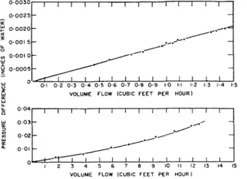
0 . 0 0 1 WFIG. 6.
.
.
.AIR FI.OW US. PRESSURE DIFFERENCE FOR INNER PANE USED IN \TAPOR DIFFUSION ~\~~EASUKBAIENTSI I I I I I 1 1 1 1
-
5 -.*.?
/& 0 --
J - 0 ' 5 0 ' 6 0 1 7 J 0 0 1 9 1'0 1 ' 1 1'2 IL3 1'4 1 5 VOLUME FLOW (CUBIC F E E T PER HOURI= w
./
W = 0 0 1 O 1 2 3 4 5 6 7 8 9 1 0 1 1 1 2 1 3 1 4 1 5of the \vincIow. Uncler this condition, thc air spacc \vill intci-change air \\-it11 the inside, thc amount of air flo\v through the outer pane b e i ~ ~ g equal to thc clifference in inflow and o u t f l o ~ \ ~ past the inner glazing.
T h e foregoing discussion of pressure distributions across double windows has shown that, with the air-flow resistance of the inside pane sufficiently higher than that of the outsidc panc, and with the openings in thc outside pane located a t the top a n d bottom of the window, thc air space can interchange air \\-it11 the outside even when an overall flow fro111 inside to outside occurs T h e relationship between these a i r flo~vs a n d condensation bet~veen the panes can bc s h o w by a simple mass balance.
If vapor flow by diffusioii is ncglectecl, the nct gain of \I-ater vapor by the air space a s a result of air flow from the insidc is appro\imatcly cqual to
wliere
Qi = volume rate of flow into the air space from the inside. d ; = density of inside air.
Wi = humidity ratio of inside air.
W , = humidity ratio of air iri space between palies.
Tlic net loss of water 17apor by the air space as a result of air flo~v from t h e out- side is approximately cclual to:
Q,d,(W,- W , ) .
. . .
(2)where
Q , = volurne rate of flow into the air spacc froin the outside. do = density of outside air.
W , = humidity ratio of outsidc air.
W , = humidity ratio of air in space between thc panes.
T o prc\.cnt conclensation the ilct gain in vatcs xpos I,! thc air spacc inust equal thc nct loss ot \vatel- I apor by the air spacc.
Equating Ecluations 1 and 2 it can bc sho\\n that,
R = minimum ratio of outside to inside air to prcvcnt condensation between panes.
To = absolute temperature of outside air, Rankine degrees. Ti = absolute temperature of inside air, Rankine degrees.
T h e values of the minimum ratio of outside to insidc a i r to prel-cnt coilclensation a t clilfcrent outsidc temperatures will depcild on insidc tcmpcratures ancl relative humidities. Valucs gi\;en in Tablc 4 arc based on humidity ratios for insiclc, air space, and outsiclc corresponding t o saturation a t the temperature of thc inner and outer panes and of outside air respectively, using the same conductances as for Table 1. Thc \ d u e of the minimum ratio increases with decreasing outside tcmpcsaturc.
Another factor t h a t j)l~ocluccs total prcssusc diffcrcnces bctwcen the air space and outsidc is a cliangc in air-spacc tcmpcrature. If the I\-inclo~v is not sealed this pres-
sure differencc \\-ill cause air flow t o or from the air space and the ~vindow breathes.
The total amount of air interchange can be calculated from the perfect gas laws and \\.ill depend on the nlajinitudc of the temperature change a n d t h e volume of t h e air enclosed in the sllacc bc:t:~~cen t h e panes. \\.l~ethcr the air space will lose or gain water \.al)or as a result of t:his mechanisnl \\.ill clel>cntl or1 whether t h e major open- ings arc al-ountl tllc outer or inner panes.
Laboratory stuclics we]-e carried out, based on thc foregoing considerations, to cletermine the degrce of vcnting of the air space t o outside required to overcome condensation I~etween the panes of a simple \~-ood sash window. Details of the unit are given in Fig. 3. The inner glazing, contained in a metal frame n-it11 a rubber gasket, was tiscd to the mood sash with alunlinu~ll clips ~vhile the outer glazing was sealed to the sash ~ v i t h glazing con~pound. The resistance to air a n d water-vapor flo~v around thc outcr pane was alterccl Ily opening or closing %-in. diam vent holes providecl in the top and bottom mclnbcrs of the sash. The vcnt holes were approsi- mately 1 in. long, mc.asurcd along tllcir ccntcr-lincs.
In discussing the mechanisms of \.apor transmission in to and o u t of the air space of double ~vindolvs! transfcr Ily diffusion and by air flou. have been dealt with separ- ately. Both mechanisms \\.ill operate s i m u l t a ~ ~ e o ~ r s l y , however, a n d \\;ill interact in an actual installation, malcing i t impossible to determine their relative contribu- tion to vapor flo1v. Separate measurements \\-ere therefore macle of the Ivater vapor diffusion and air flolv characteristics of the cracl<s around the inner pane and of t h e vent holes a r o ~ ~ n d tlic outcr pane a s a lrieans of assessing the relative importance of the two ~nechanisms.
Fig. 4 sllows the arrangement used for measuring the vapor cli~fusion characteris- tics of the cracks around the inner pane. There were 110 vent holes around the outer
pane in the sash used for this study and the .i\;ood was sealed \\-it11 w a s to make i t essentially inlpermeable. T h e procedure consisted of supplying dry air to the win- clolv air space a t a Itnown rate and ~neasuring the humidity rise. If there is no total pressure difference b e t m e n the space and outside, vapor transfer is by diffusion only. A t equilil~riu~n, the amount of vapor transferred by diffusion through t h e craclcs around the inner glazing is equal to the gain in moisture of t h e air flowing through the ~vindow space. T h u s ,
Ad = rate of water vapor transfer past the inner glazing, g r a i ~ ~ s per hour.
D = vapor diffusion coefficient for the inner glazing, gralns per (hour) (il~chcs mercury).
AP, = difference i n partial pressure of water vapor across the ir~ner glazing, inches mercury.
Q = volume rate of Row of dry air being circulated cubic feet per hour. d, = density of air being circulated, pounds per cubic foot.
M/,
= humidity ratio of circulating air a t inlet to the window space, grains per pound dry air.Ft'z = humidity ratio of circulating air at the outlet from the window space, grains per pound dry air.
'I'lle humidity of the air being circulated was ~ncasurcd a t the inlet and outlet of the ~ ~ i n c l o m spacc with 2 elcctric llygron~eter elenlclrts. 'I'hcsc \\,ere calibrated prior
to and follo\\ring the tcst in an apparatus providing controlled conditions with an absolute accuracy of &0.1 percent relative humidity. T h e conditions in the room in which the tests \\,ere carried out were controlled a t 72 F and 50 percent relative humidity within close tolerances.
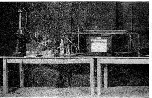
T h e air \\!as circulatccl by a small diaphragm pump and the rate \\as measured usith a capillary tube flownlcter in conjunction with a sensitive micromanometer.
A displacement-tlpe micron~anometer in conjunction with a single pan analytical balance was ~ ~ s e c l throughout the test to nleasure the total pressure tlifterence be- tween the \\rindow space and the laboratory. A change in the balance reading of 1 milligralll corresponds to about 0.0001 in. of \\rater. Since there was no change, it can be concluded t h a t the total pressure difference across the inner glazing was essentially zero throughout the test.
T h e vapor diffusion coefficient, basecl on Equation 4, using the average of initial and final calibrations for the electric humidity sensing elements was 1.89 grains per (hr) (in. Hg). T h e possible error in the measurement is about &20 percent.
.,
k , 0 0 6 & t;k
'
, 0 0 4:
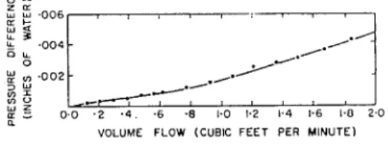
,,, , 0 0 2 3 w $ 6 .+--*/ W Z a ; 0 . 0 . 2 . 4 . . 6 .8 1.0 1.2 1.4 1.6 1.0 2 . 0 nVOLUME FLOW (CUBIC F E E T PER MINUTE)
FIG. 7.
.
.
.AIR FLOW VS. PRESSURE DIFFER-ENCE FOR OUTSIDE PANE WITH 46 VENT I ~ O L B S
Rather than atteillpt to make direct measurenle~~ts of the vapor diffusion coeffi- cients of the %-in. diam vent holes, tests were carried o u t on a %-in. dialn copper tube with 90 deg bend, mounted in a permeability cup as shown in Fig. 5. T h e tests were carried out in a conclitioned cabinet maintained a t 73 F and 50 percent relative humidity. The open end of the tube was protected froin direct impingenlent of air being circulated 11-ithin the cabinet. The permeance obtaillecl for the tube a s shown in Fig. 5 was 90 grains per (hr) (sq ft) (in. Hg). Tests were also carried out on a straight %-in. diam tube 1% in. long and the perlneance obtained was 100 grains per (hr) (sq ft) (in. Hg). The corresponding permeability is 150 grains per (hr) (sq ft) (in. I-Ig per in.).
Air flour tests were carried out 011 the inner glazing to cleternline its leakage char-
acteristics during the vapor transinission measurements. T h e method consistecl of supplying air to the window air space a t the rate required to maintain a given pres- sure difference across the window. Pressure clifferenccs greater than 0.005 in. of water were incasurccl with a nlicrolnanometer sensitive to about 0.001 in. of water; pressure differences less than this were measured \\.it11 the displacement manometer and analytical balance sensitive to 0.0001 in. HzO. Subsequent calibration of this manometer has sho~vn t h a t the error in measurement a t pressures less than 0.005 is about plus 15 percent. Air flows less than about 2 CLI ft per hr were luade with the capillary tube flowmeter previously described. A t higher flows a calil~rated vari- able area flowineter was used.
T h e results of thc air flow incasurernents on thc inner glazing are shown in Fig. 6.
562 ASI-I IZAE TR;\NSACTIONS
air Ro\v 11 as found to be independent of the direction of flo\\r a t pressures less than 0.015 in. of water.
LIeasurements \\rere made to determine the air-flow characteristics of the M-in. cliam \.ent holes in the sash around the outer pane, using the equipment just referred to. The flow through the 46 vent holes was not exactly 46 times t h a t through t h e single vent hole since the lioles varied in resistance, having been drilled by hand. Fig. 7 sho\\s the flow characteristics of 46 vent holes in the range of prcssure dif- fercnccs normally pro\iclecl by chimney action bctxveen the air spacc and outside. All Ho\vs have bcen conxerted \\,it11 refcrcnce to air a t 0.075 111 per cu f t .
,
.
l o assess the re1atix.c i~rlportance of vapor flow by diffusion and by air flow i n relation t o conclensation between the pancs of double \vindo\\7s, it is necessary t o ccnsider \\-hat total pressure differences are a\,ailable across the inner and outer panes a t different conditions of ov-erall inside-outside prcssure difference. This can :, be clone with reference to the pressurc distributions illustrated in Figs. 1 and 2. Figs. l a ancl 2b a r e ol particular interest \\~ith respect to thc test window since they represent arrangements in ~vhich chimney action bet\\ven the air in the \\rindow space ancl outside can bc utilized.
\Yitli the center of the \\'indo\\. a t tlic neutral zone, as illustrated in Fig. 2a, t h e prcssurc diffcrcnce across thc botto111 and top openings of the outer pane is,
Po = prcssurc diffcrcnce across top or bottom of outer panc, poullds per square foot.
I = height of window space, feet.
(1, = density of outside air, p o ~ ~ n d s per cubic foot.
d , = density of air in window space, pounds per cubic foot.
g = accclcration of gravity, 32.2 ft pcr [second) (second).
g, = proportionality constant, 32.2 (mass Ib) (ft) per (force Ib) (sec) (sec).
,
.
I l1i.j can be c q ~ ~ - c s s c d as
T s - T o
12, = 3.821
. . .
( 6 )T , X T o
h , = pressure difference across top or bottom of outer pane with window a t neutral zone, inches of water.
T, = mean temperature of air space, Rankine dcgrees.
T o = outside air temperature, Rankine degrees.
Siliiilarl~- the pressure differences across thc inner pane a t the top or bottom \\-it11 t h e \vir~do\\- a t the neutral Lone is,
hi = pressure difference across top or bottom of inner panc, inches of water.
T, = inside air temperature, Ranliine degrces.
\iTith the centcr of the winclo\\l above the neutral zone as illustratetl in Fig. 2b, thc \\.intlo\\r air spacc prcssure d c l ~ c n d s on the relative resistance to air flo~r, of cracks
CONDEKSXTIOX RIIT\VEEX P.ISES OF Dourir.~ \ \ ~ ~ s o o m s , BY \ \ ' ~ ~ s o s a r o Sow.\rc 563
or openir~gi m o ~ ~ n t l the inner and outer panes. Flow Iron1 outsitlc t o the a i r space occurs through the openings arouncl the o~~tyicle pane belo\v level 11. Thi5 \ olume, together with the air flo\v through cracks around the inner pane, fl0u.s t h r o ~ ~ g t i openings arouncl the outer pane alxn e le\.t=l 11. If the ratio of o~rtsicle air t o inside air i i that clefinetl t)!~ l<cl~ration 3 (lien,
QT = flow tllro~~gh cracks around outer pane above level 1,.
But @,[. aiid I;), can be e\pressecl in terms of nxeeasured flow characteristics. F o r the test window the relationship is simple since, as sho\on in Fig. 7, flow is clircctly pro- portional to pressure cliflerence a t the small pressure differences producecl by chinx- ney action and the bent holes are locatecl onl! a t top and b o t t o ~ n . Thlls,
and
QT = Co(do - d,)(l - ll ) g / g c . . .
where
C, = flow coefficient for vent holes.
1, = distance from the bottoril vent holes tn the level where air space and out- side pressures are equal, feet.
Substituting Ecluations 9 ailcl 10 in E q ~ i a t i o ~ i 8
I t folio\\-s, with reference to Fig. 211 t h a t
IL', = pressure difference across 1)ottom of outer pane with wintlow al~ove ncutral zone, inches of water.
Also
where
1 ~ ' ; = pressure difference across center of inner pane with window above neutral zone, inches of water.
IL = inside+~~tsitle air pressure difference across center of wiridow, inc:hes of water.
TO assess the relati\-e rates of \,apor flow by diffusion and air flow in t o ancl out of the air space of the test \vinclo\v, outside conditions of 0 I; ancl 85 percent relative
humidity and inside conditions of 7 0 F and 25 percent relative humidity have been chosen. T h e vapor pressure in t h e space has been taken to correspond to satura- tion a t the temperature of the inside surface of the outer pane. T h i s temperature was calculated assuming an outside surface conductance of 4.0 (for a 10 iuph wind) and a
U
value of 0.51. For these conditions R in Equation 3 equals 3.42.Based on the measured diffusion coefficient, the vapor transmission by diffusion through the cracks around the inner pane is 0.23 grains per hr. T h e vapor hdns- mission by diffusion through two %-in. vent holes, assuming one a t t h e top and bot- tom, is 0.0019 grains per hr. Calculated vapor transmission rates b y air flow for different conditions of inside-outside total pressure differences are given ill Table 5. These values are based on the measured air flow characteristics and t h e simple rela- tionships developed in the preceding section.
I t can be seen t h a t the relative importance of vapor transinission b y diffusion a n d air flow through craclrs around the inner glazing depends to a considerable estent o n
neutral zone a t center h = O
neutral zone at bottom edge h = 0.002
h = 0.004 h = 0.014
the inside-outside total pressure difference. \Vith the iieutral zone a t the center of the windolv, the vapor transfer by air flow is about twice t h a t by diffusion; with the neutral zone a t the bottom edge the ratio is a b o u t 10 for t h e conditions chosen. At higher total pressure differences, vapor transfer by diffusion becomes relatively insignificant. T h e vapor transfer through the %-in. vent holes by diffusion is un- important compared to t h a t by air flow, regardless of the total pressure difference, so long a s the vents are distributed so that chimney action can occur between t h e air space and outside.
The amount of venting of the air space to outside required to maintain vapor outflow equal t o inflow, and thus t o avoid condensation between the panes, can be determined from Table 5 for the conditions chosen. With the neutral zone a t t h e center of the window, 2 or 3 vent holes a t top and bottom are required depending on the contribution of diffusion to vapor transfer in t o the space. \Yith the neutral zone a t the bottom edge 10 vent holes a t top and bottom are required.
At pressure differences of 0.004 and 0.014 respectively, some twenty and sixty %-in. vents are required. These pressure differences were chosen from Table 2 t o represent those that might occur across leeward windo\vs with winds of 5 and 10 mph. If vapor transfer f r o ~ n the air space t o outside by diffusion is the only avail- able mechanism, the number of vents required is many times the values just given. Air flow in t o and out of the window space a s a result of breathixg action due t o temperature changes has been mentioned a s a means of vapor transfer. I t can be
C O N D E N ~ A ' ~ ~ O N ULI\VEEK PANES 0 1 7 DOUBLE WINDOWS, BY WILSON A N D NOWAI< 565
shown for the test \vindo\v that the average air floiil in to or out of the space due to a daily outside temperature cycle from -20 F to f 2 0
F
is about 0.001 cu f t per hr. This compares with a calculated air flow through the cracks around the inner glazing as a result of chimney action, with the \\rindo\vat the neutral zone, of 0.42 cu ft per hr. Thus, for the test Ivindow, the amount of vapor transfer as a result of breathing action is insignificant relative to t h a t as a result of chi~nney action. T h e importance of brentl~ing action in moving water vapor in to or out of the air space of a double window ill depend on its air leakage characteristics and the volume ol air between the panes. Unless the air space is unusually thick, breathit~g action will have only a secondary effect on all but extremely tight \vindows.COLD Iiooar TESTS
I n predicting lor the test \vintlow the amount of \.enting of thc air space t o outsidc required to overconle condcl~sation under spccificd conclitions, a n r ~ ~ n l ~ e r of sim-
Cold room at 0 F Warm room at 70 F and
38% relative humidity
I
3 top and bottom
/
borderline 4 top and bottom borderline 5 top and bottom adequate 6 top and bottom adequate23 bottom inadeauate
1
241
23 topI
I
inadequateplifications were introduced. For examplc, in clctermining the stack action I~etween the air space and outside i t was aisuinetl that thc air space temperature could be taken as cqual t o thc mean of the temperatures of the t ~ o panes. Roth h o r i ~ o r ~ t a l and vertical temperature gradients in the space were tlisrcgardctl.
Colcl rooin tests were ~~ntlertakcn to determine by direct obscr\ ation thc ainou~lt of venting required unclcr specific conditions. For this stucly, a test \vinclow \vas installed in a \vall panel which formed p a r t of a partition between a \\-arm a n d cold room. The teinpcrature of the cold room could be controlled over a wide range within ~k0.25 F deg, with floor to ceiling temperature gradients not exceeding 1 F
deg. The relative humidity in the cold room \!,as about 50 percent. Air move- ment over the wintlo\v uasdownward a t about 6 inph. Closc control of tempera- ture and humidity \\?as also provided in the \17arm room.
\\-it11 a warn1 rooin tenlperature of 70 F a t the windo\\, le>el, observations of condensation between the panes were made a t a number of cold room temperatures and warin room hunliclities, with various degrees of venting of the air space to the cold room. Results obtained with a cold room temperature of 0 F and a warm room 11umidit> of 38 percent are given in Table 6. None of the conditions c o ~ e r e d by Table 6 led t o inore than light deposits of frost. For the 2 venting conditions judged adequate, the frost was limited to small patches in the two upper corners. T h e vents were located near the center of the top and bottom edges.
It
is thought t h a t if they had been inore uniformly dispersed t h e window \vould have remained566 ASHRAE TRANSACTIOSS
cntircl! clcal-. For the t\vo \.cnting arrangements judged to be borderline, there vcrc two or three small adclitional patches of light frost near the bottom 01 the win- c l o ~ ~ . \TVith the openings a t top or bottom only there \\ere t u o light bands of frost from t o p to bottom on either side of center.
The ~ i n d o ~ v unit usecl for the cold room tests was a different specimen fro111 t h a t used for the \ apor cliffusion nlcasurcmcnts. Measurenlcnts were made to deter-
mine the air flow characteristics of the cracks around the inner pane and the results are gi~.cn in Fig. 8. This unit was found t o be sonle\vhat tighter than the other specimen, as can bc seen from Fig. 6. I t was found that the degree of tightening of the scrc\\s holding the aluminunl clips affected the tightness of the window. T h e
VOLUME FLOW (CUBIC FEET PER HOUR )
air Rev characteristics shov n in Fig. 8 are b e l i c ~ cd t o be r c p r c s c n t a t i ~ c of the unit a5 installccl in the cold room.
AIcasurcnlents of pressure difference between cold and \\arm rooms 15 ere made t o determine the total pressure clistribution 01 er the test \\indo~v. Results of these measure~nents n ith the cold room a t 0 F, given in Fig. 9, indicate t h a t the ncutral zone was between the center and bottom edge of the window.
No measuremeilts of the vapor diffusion characteristics of the craclts around t h e inner glazing used in the cold room tests were made. Predictions of the amount of venting required to prevent condensation between the panes must therefore b e based on air flow alone. Such calculations show t h a t with the neutral zone a t t h e center of the n-indo~v, 1 vent holes top and bottom are required, while 4vent holes top and bottom are needed ~vit11 t h e neutral zone a t the bottom edge of the window. The vapor pressure in the air space was assumcd t o correspond to saturation a t t h e nliniinum tcinpcraturc measured on the inside surfacc of the outer pane. The coin- parison of J-apor transfer by diffusion and air Row for thc inner glazing uscd in t h e diffusion measurements has s h o ~ v n that diffusion contributes a signilicacit propor- tion of the vapor flow a t these snlall pressure differences. Calculations for this unit under the cold room conditions show t h a t the flow by diffusion is from one-third t o one-half t h a t by air flow, wit11 the window a t t h e neutral zone. Applying this proportion to the window unit tested in the cold room, the number of vent holes
required becomes 2 ant1
-1!5,
~ ~ i t h tht, neutral 7one a t t l ~ e ccntcr ant1 I~ottorn ctlgc. respecti~~ely.There is fair agreement I~et\veen the cold room ol,ser\.ations ant1 the estimatetl amount of enting of the air space required to o\.ercome condensation bet\\leen the
7 .
panes. I he coltl roo111 tests \\ere not itleal for such a con~pariso~l I)eca~r\e ol tllc quite small total pressure tliflerences provided, \vhen accurate mea\L~~erncnts of pressure and flow become difficult. Further~aore, s~ n a l l changes in the location of the neutral zone \\.ill lead to relatively large cllanges in the venting rerluirements.
PRESSURE DIFFERENCE (INCHES OF WATER)
FIG. 9.
. .
.PRESSURE DIFFERENCE I ~ E T W E E N \I':\RAIA m COLD Roonls vs. HEIGIIT
I t is clear t h a t coltl room s t ~ ~ d i e s of condensation between the panes of double windo~vs are o i little 1,alue ~ ~ n l e s s the total pressure dilferences across the n.indo~v are m e a s ~ ~ r e d . Even then, the o b s e r ~ ations are of use only in confirming some other approach for determining condensation performance, unless the total pressure differences correspontl to those for which the \vindo\v is being considered.
I t has been s h o n n t h a t veliting of thc air space to outside tlirougll chilnney action is a n efiectiie means of controlling corldensation between the panes of double windows. I t will be recognized, however, that ewessive venting will lower the mean temperature of the air space and increase ox erall heat transmission. Taking the air space a s equivalent to I surface conductances its mean te~nperature can be
568 ASI-IRAE T ~ a s s . i c ~ ~ o ~ s
estimated bl equating the hcat floiv through the inner pane to the heat Ilo~v througli the outer pane plus that carried away by the ventilating air. The apparent overall heat transn~ission coefficient ivith venting can then be expressed as
U' = apparent overall heat transmission coefficient with venting.
U = overall heat transmission coefficient without venting.
Ti = inside air teinperature.
T,' = mean air space temperature with venting. T , = mean air space temperature without venting.
On this basis the percentage increase in the overall heat transnlission coefficient has been calculatecl with venting a s required a t 0 F and 85 percent relati1.e humidity outside, and 70 F and 25 percent relative humidity inside.
For the test \\~indow used in the diffusion measureinents, the increase in U value is 1 percent \\.it11 a total pressure difference of 0.004 in, of water, a n d 2.5 percent with a total pressure difference of 0.014 in. of water. The increase in
U
alue for the window used in the cold roo111 studies is less than 1 percent a t a total pressure dif- ference of 0.014 in. of water. Both these specimens are, ho~vever, relatively tight. At a presiure differeilce of 0.301 in. of water (equivalent to the velocity pressure of wind a t 25 mph) the air lealrage rate of the latter is 0.04 to 0.05 cu f t per n ~ i n per f t of crack.Leakage through the other specimen was not measured a t this pressure difference. I t can be estimated, however, assuilling t h a t the flow can be expressed as
where
c = Row coefficient.
tt = exponent of flow, between ? $ and 1.
The exponent )L is about 0.55 for tlre test units. T h e flow through the spcci~nen
used in the clilfusion tests is then 0.07 to 0.08 cu f t per inin per ft of crack a t a pres- sure difference of 0.301 in. of \\rater.
These leakage rates are probably representative of the leakage through cracks around the inner pane ot illany residential and commercial windows of the case- ment, awning, or hopper types, haling inner and outer glazing in the same sash. There are other window t j pes having a much lower resistance to flow from inside
-
to the air space. For example, the Specification of the Aluminum \I7intlo~\. Manu- facturers Association permits a maximum air lealrage rate of 0.5 cu f t per min per f t of crack a t a pressure difference of 0.301 in. of water for a double double-hungwin do^.^
An approximation of the venting requirements and the resulting increase in
U
value for such a \vindo\v, for the conditions just referred to, can be made by extrapo- lating flo~v rates on the basis of Equation 15. If it is assumed t h a t all the resistance to flow is from inside to the air space, the increase in U value is about 9 percent a t a pressure difference of 0.001 in. of water and about 16 percent a t a pressure difference of 0.014 in. of water. If it is assumed that the resistance to flow is nornlally evenly divided bett~reen inner and outer sash the increases in U value are 13 percent a n d
2 1 percent respectively with the required venting. T h e advantage of a t i g h t inner sash i s a p p a r e n t .
I n applying principles of venting t o t h e design of a window, a m b i e n t conditions should be carefully selected. I t is usually n o t necessary t o design for t h e m o s t es- trerne condition, since s o m e condensation can generally b e toleratecl a n d t i m e is required for i t s accumulation. Since information o n t h e a c t u a l total pressure differ- ences across building walls is q u i t e limited, application of venting principles should be combined w i t h directed observations of field performance.
1. With outside t e ~ u p e r a t u r e s lower t h a n inside, condensation will ulti~uately occur on the inside surface of the outer pane of double windows if the gain in water vapor to the window space is greater than the loss.
2. Vapor pressure differences available for diffusion of water vapor into the air spaces are several times greater t h a n those available for diffusion from the air space t o outside, the ratio of the pressure differences increasing with decreasing outside temperature.
3. Vapor transfer as a result of air flow will depend on t h e total pressure difference across the window and the relative resistance and distribution of cracks around inner and outer panes a s well a s psychrometric conditions.
4. For windows having air leakage rates equal to or greater than the test windows (0.05 cu ft per mi11 per ft of crack a t 0.301 in. of watcr), the vapor transfer b y air flow will probably be several times t h a t by diffusion even with the window a t thc neutral zone, the ratio increasing as the height above the neutral zone increases.
5. With the air flow resistance of the inside pane sufficiently higher t h a n t h a t of the outside pane, and with openings around t h e outside pane located a t the t o p and bottom of the air space, the air space can i n t c r c h a ~ ~ g e air with the outsidc by clzi?n?zey action even with inside pressures greater than outside. Such venting of t h e space can be used effec- tively to prevent cor~densation between the panes if t h e amount of outside air inter- change is large in relation t o the air flow to the space from inside. The ratio of outside t o inside air required to prevent condensation depends only on inside and outside psy- chrometric conditions.
6 . T h e number of vents required t o prevcnt conderlsation for give11 design conditioils can be predicted from simple pressure relationships, providing the air flow characteris- tics of t h e vents and the cracks around the inner pane are knoxvn.
7. Excessive air intcrchange between the air spacc and outside can rcsult in significant increases in the overall heat transmission coefficient. I t may therefore be impractical to apply vcnting t o windows having high leakage rates.
8. There is a lack of detailed information on actual coriditioi~s in buildings t h a t affect condensatiorl on the insicle surfacc of the outcr pane. I n particular, further inforruation on total air pressurc differences bctmcen inside and outside, a n d inside rclative humidi- ties, is desirable.
9. Unless conditions of tcst, includir~g total air prcssure differences, are similar t o those expected in the field the results of observations of condensation on the outer pane in cold room studies are not directly applicable and are of doubtful value except for research purposes.
T h e a u t h o r s a r e i n d e b t e d t o D. G. Stephenson f o r assistance in t h e measurement of a i r pressure differences with t h e displacement-typc micl-onlanometer, t o I(. R.
570 ASI-IRAE TR~INSACTIONS
assistant, who assembled t h e equipment a n d took m o s t of the records. The advice of
N.
B. H u t c h e o n , Assistant Director of t h c Division of Building Research is grate- fully acknowledged.D. R. Bahnfleth, T . D. Moseley, and W. S. Harris: ASHAE RESEARCH REPORT NO. 1615-Measurement of infiltration in two residences. Part 11: Comparison of variables affecting infiltration (ASIIAE TRANSACTIONS, Vol. 63, 1957, p. 453).
? T . C. Min: ASHAE RESEARCH REPORT NO. 1643-Winter infiltration through swinging-door entrances in multi-story buildings (ASHAE TRANSACTIONS, Vol. 64, 1958, p. 421).
. 4 l ? r n ~ i n ~ r ~ n bvindonos 1957. Specificaf.iom-, 1957. (Alumin~u~n Window ;\lanufac- urers Association).
DISCUSSION
R. \V. MCICINLEY, Pittsburgh, Pa.: The authors have added much useful information regarding vapor transmission a n d condensation characteristics of double windows. They have indicated that the indoor edge seal is especially important since it can im- portantly influence the thermal insulating value of the window. Usually, insulation is the primary justification for double glass.
Since most windows are included in the building so t h a t one may see in or out, t h e y are subject to critical visual examination. Therefore, it is important either to provide for regular, convenient cleaning of all glass surfaces or to design the double windows so that cleaning of inner surfaces is not necessary. This is another important reason for a reliable interior edge seal a n d for reducing condensation t o a minimum. Designs should either prevent breathing co?lzpletely or should filter dust from the entering air (i.e. the air entering the space between the panes.) If a unit is to breathe, i t should breathe outdoor air only.
Unsightly and irregular accumulations of dirt on the interior surfaces of the glass c a n and should be avoided.