HAL Id: hal-03093664
https://hal.archives-ouvertes.fr/hal-03093664
Submitted on 4 Jan 2021
HAL is a multi-disciplinary open access
archive for the deposit and dissemination of
sci-entific research documents, whether they are
pub-lished or not. The documents may come from
teaching and research institutions in France or
abroad, or from public or private research centers.
L’archive ouverte pluridisciplinaire HAL, est
destinée au dépôt et à la diffusion de documents
scientifiques de niveau recherche, publiés ou non,
émanant des établissements d’enseignement et de
recherche français ou étrangers, des laboratoires
publics ou privés.
Vincent Loriot
To cite this version:
Vincent Loriot. Automatic CEP locking and optimization for a Ti:Sa femtosecond oscillator. OSA
Continuum, OSA Publishing, 2020, 3 (11), pp.2976-2981. �10.1364/OSAC.402964�. �hal-03093664�
Automatic CEP locking and optimization for a
Ti:Sa femtosecond oscillator
V. L
ORIOT*Université Lyon, Université Claude Bernard Lyon 1, CNRS, Institut Lumière Matière, F-69622, Villeurbanne, France
Abstract: This paper presents a software solution to automatically lock and optimize the carrier envelope phase (CEP) of a femtosecond titanium:sapphire (Ti:Sa) based oscillator following the standard optical arrangement. The solution also mitigates the usual limited-range actuator problem of the slow feedback loop. The principle is to control the relevant stabilization parameters with a single computer to mimic the manual action. After calibration of the piezoelectric actuator, four preliminary measurements are required to locate the CEP-locking point. Then, the algorithm optimizes the CEP performance. Only a few seconds are required to automatically lock and optimize the CEP.
© 2020 Optical Society of America under the terms of theOSA Open Access Publishing Agreement
1. Introduction
With the discovery of mode locking, it became possible to generate intense pulses of few tens of femtoseconds [1]. By further broadening of the spectrum, it is even possible to post-compress the pulses to the few optical cycle regime [2–4] with eventually high average power [5], and even down to the single cycle pulse limit [6,7]. For such ultrashort pulses, the usual slow varying envelope approximation fails. Interestingly, the relative position between the envelope of the pulse and its carrier frequency can imply strong changes in non-linear optical physics. This carrier envelope phase (CEP) hence becomes a crucial parameter in the few cycle regime that can change the outcome of the non-linear light-matter interaction [8–10].
The CEP stabilization of a femtosecond oscillator means that the group phase offset per cavity round trip is maintained. In the spectral domain, it corresponds to stabilizing the offset of the frequency comb [11]. A widely used method to stabilize the CEP of a Ti:Sa oscillator is based on closing a feedback loop with the locking electronics (XPS800-E) from Menlo Systems [12–15]. In our case, the XPS800-E drives a fast feedback loop that acts on the power of the oscillator pump laser for small corrections of the cavity dispersion using the Kerr effect, and also a slow feedback loop that drives a piezoelectric actuator to finely control the position of a prism inside the cavity. When the fast loop gets close to the edge of its range, the slow loop changes the prism position into the cavity to recenter the fast loop range. However, when the slow loop reaches the limit of its range, no extra compensation is available and the CEP locking is lost. To prevent such out-of-range situation, some solutions already exist. For instance, it is possible to change the actuator technology, or to tune the temperature of the femtosecond oscillator chiller [15], having a constant environement maintening the slow loop in its range [16], among others, or by changing the optical design [17–20].
In this paper, a Labview-based software is proposed, which automatically locks the CEP and prevents problems due to the limited range of the slow feedback loop actuator. The software drives all the relevant parameters to reproduce the manual actions required to lock and optimize the CEP of a Ti:Sa femtosecond oscillator. Also, when the actuator gets close to its range limit, the program unlocks the CEP, locates the other locking point (on the other side of its range), relocks the CEP and optimizes its performance. After describing the setup employed, we show how the software proceeds on a case example.
#402964 https://doi.org/10.1364/OSAC.402964
2. CEP stabilization setup
The proposed CEP automatic locking setup is schematically shown in Fig.1. It is composed of the standard CEP locking elements: femtosecond oscillator, f-2f measurement [21], XPS800-E, oscilloscope (Keysight DSO 1052B), spectrum analyzer (Rigol DSA815), and a computer that reads out all the relevant parameters and automatically controls the CEP stabilization. The Vitara-T (Coherent) is a robust femtosecond oscillator that is built in a sealed monolithic housing. It is a hands-free laser that uses several actuators to control modelocking, spectral tuning and the CEP active elements. The measurement of the CEO is performed by a standard f-2f device that requires '250-300 mW (i.e. half of the output power).This part of the beam is sent into a photonic-crystal fiber (PCF) that produces more than an octave-spanning supercontinuum. A dichroic mirror splits the spectrum into a visible and an infrared part. The part of the spectrum around 1064 nm is up-converted to 532 nm using a BBO crystal and overlapped with the fundamental 532 nm of the initial supercontinuum. Spectral, spatial and temporal overlap must be maintained to optimize the beat signal. The relative intensity of the two perpendicular polarized beams is controlled with a half-wave plate and a polarizer assembly. The 532 nm is purified using an interference filter before the detection by an avalanche photodiode (APD). The error signal generation and the compensation management of the CEP is performed by a XPS800-E
Fig. 1. Schematic representation of the setup. The pump laser is slightly modulated by
an acousto-optic modulator (AOM) before pumping the Ti:Sa crystal of the Vitara. A piezoelectric translation is located on one of the prisms inside the laser cavity. When the beam leaves the cavity, half of its power is launched into a f-2f carrier envelope offset (CEO) measurement setup. It is composed of a photonic crystal fiber (PCF) that generates white light which is sent into an interferometer that separates the visible part from the infrared part of the spectrum. The infrared part of the spectrum is up-converted into the visible using a BBO crystal. Both beams are recombined and spectrally filtered around 532 nm and the interference between the beams is measured by an avalanche photodiode (APD). The signal of the avalanche photodiode is sent to the XPS800-E box and a spectrum analyzer. The XPS800-E box drives the AOM for the fast feedback loop and the piezo of the prism for the slow loop. The control loop error signal is sent to an oscilloscope where it is digitized. A read/write connection is established between the computer and the oscilloscope, the XPS800-E and the spectrum analyzer to drive the automatic CEP stabilization.
device that drives both the fast and the slow stabilization loops. The fast loop (up to 30 kHz) compensates the small but quick dispersion changes. This control is done by an acousto-optic modulation of the pump laser intensity that finely controls the Kerr index of the Ti:Sa crystal. The acousto-optic device diffracts out a small fraction of the pump beam to modulate the intra-cavity power. The slow loop (sub-Hertz regime) allows a change of the group phase offset per cavity round trip of about half an optical cycle i.e. ' 1.1π rad. This loop controls the prism position in the beam path of the cavity, using a piezoelectric actuator. The CEP stabilization can be achieved by manually tuning the prism position close to the expected locking point, and the final stabilization is found by the fast loop. When the fast-loop gets close to the edge of its range, the slow loop moves the prism to re-center the fast loop position. However, when the slow loop arrives at the limit of its range, no additional parameter can be tuned to maintain the CEP stabilization. The out-of-range event of the slow loop can lead to strong perturbations of the femtosecond oscillator and, in some rare cases, loss of modelocking. A ∼ 1.1π range for the slow loop typically allows several hours working time with CEP, depending on the stability of the environment. However, an out-of-range event of the slow loop does not mean that the oscillator cannot be CEP locked anymore. On the contrary, a second locking point exists on the other side of its range using a beat signal of opposite polarity. In other words, it is always possible to stabilize the CEP. However, close to the out-of-range event, manual intervention is required to move the prism to the second locking point and reverse the polarity. The strategy that reproduces this method is presented in the following section.
3. Automatic CEP-locking strategy
The automatic CEP-locking is beneficial in two situations, (i) for a non-expert CEP-stabilization that requires a CEP stabilized laser source and (ii) for the CEP re-locking in case the slow loop reaches the edge of its range. The principle of the method is presented in Fig.2. The expected working condition for the CEP stabilization is a ±π/2 CEP shift between two following pulses (the sign is defined by the polarity). A further selection of the pulses with the same CEP can be implemented afterward with a pulse picker that isolates a pulse every 4N pulses to get ±2πN phase difference between the pulses (N integer). Under that condition, the RF power spectra of the beat note signal measured by the APD is composed of two peaks at 20 MHz (frep/4) and
60 MHz (3frep/4) for an frep= 80 MHz repetition rate cavity. These two frequencies (f1and f2)
are related to each other by the following equation
f2= frep− f1; with 0<f1< frep
2 = 40 MHz. (1)
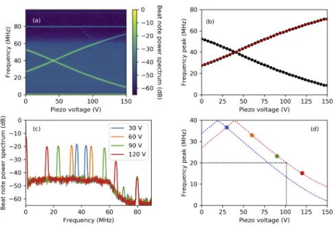
As shown in Fig.2(a-b), the position of such peaks can be controlled by changing the voltage on the piezoelectric actuator (slow loop). Because of the range of '1.1π rad of the piezo actuator and the two possible polarities, it is always possible to find a piezo voltage that produces a peak at 20 MHz. To identify this position, it is possible to scan the piezo voltage such as in Fig.2(a) and extract the position of f1and f2as shown in Fig.2(b). As a function of the piezo voltage (p),
the peak positions can be described by a third order polynomial as follows
f1,2(p)= a0+ a1p+ a2p2+ a3p3, (2)
with aithe polynomial coefficients of the ithorder. Depending on the environmental conditions,
only the a0 value changes significantly, the others ai>0terms can be considered as constants.
Once the ai>0coefficients are determined, four isolated measurements (Fig.2(c)) are required to
unambiguously determine a0, considering the two different polarities and the particular cases
(f1,2 ≈ 0 MHz or f1,2≈ 40 MHz). As shown in Fig.2(d) the polarity can easily be identified.
Fig. 2. (a) Piezo voltage scan (step of 2.5 V) of the beat note power spectra. (b) Peaks
frequencies of (a) with its third order polynomial fitting that calibrate the aicoefficients of
Eq. (2). (c) Four beat note power spectra measured used to locate the locking point. (d) Position of the maxima of the peaks shown in (c) (maintaining the color code) with the two possible polarities that reproduce the measurement at 30 V (adjusting a0) in dashed line. The
piezo voltage that corresponds to a frequency of 20 MHz is shown by the black dotted line.
and the quick loop can lock the CEP. To avoid the usual hysteresis problem of piezo actuators, the voltage is always returned to zero before applying a new value.
A robust CEP-locking is achieved with feedback control which is not too tight. After the initial CEP-locking, the performance is automatically optimized by tuning the PID (Proportional - Integral - Derivative) parameters. This procedure is performed by measuring the CEP error signal RMS noise (using the oscilloscope) as a function of the PID parameters. An optimum ensuring high CEP performances and robust CEP-locking is automatically found. In our case, we remark that it was sufficient to optimize the P value (I= 30 kHz and D deactivated) with all others parameters optimized manually (no day-to-day drift observed on the fixed parameters). To maintain the optimum performances within a fluctuating environment, it is also possible to consider a periodic PID optimization (once every few hours in our case).
4. Results
A typical result of the automatic CEP-locking maintained over several hours is shown in Fig.3. The top graph shows the voltage of the piezo actuator (slow loop). This value follows the environment temperature fluctuation (within ±1◦C). Close to the range limit (below '3 V or above '147 V) the program automatically unlocks, finds, relocks and optimizes the CEP. The bottom graph indicates the achieved CEP performance. Despite the slow-loop compensation range limitation of 1.1π rad, the CEP is maintained below 60 mrad RMS over 15 H (manually stopped). Lets notice that in-optimization loop measurement of the CEP usually exibits smaller CEP fluctuation than an out-of-loop setup [22,23]. For a central wavelength around 800 nm, 60 mrad stability would correspond to a temporal jitter of ∼25 attosecond between the peak of the envelope and its carrier frequency oscillation.
Fig. 3. Long term CEP stabilization. (a) Applied voltage on the slow loop piezo actuator.
The dashed vertical lines indicate the automatic call of the CEP re-locking procedure (i.e. the piezo voltage gets too close to the range limit). The color of the line indicates the polarity. (b) in-loop measurement of the CEP performance where the RMS value is calculated on 20 ms acquisition samples.
5. Conclusion
A software solution to automatically lock and maintain the long term CEP stabilization is proposed for Ti:Sa oscillators under the standard configuration that eventually has a limited slow-loop compensation range. The algorithm mimics the manual CEP-locking and optimization procedure. The CEP can be stabilized without time limitations with only short (few-second) interruptions close to the range limit. The interruption time can further be reduced by improving the communication protocol. This solution is successfully used in the day-to-day basis without any manual alignment. More recent Vitara versions provide greater than 2π tuning range [24], making the range limit events less frequent. Hence, at least three locking points would be available. The software solution would be well suited to automatically lock on the most relevant locking point (in the middle of the range with the desired polarity) and, when it arrives close to the range limit, it can switch to another locking point on the other side of the range that has the same polarity. A simple calibration of the slow-loop actuator (polynomial coefficients) has first to be performed before using the four-measurement method to lock the CEP. The Labview routines are available upon resonable request and can be adapted to other oscilloscopes and network analyzers.
Funding
Centre National de la Recherche Scientifique; Agence Nationale de la Recherche (ANR-16-CE30-0012).
Acknowledgements
The author wants to thank F. Lépine for fruitful discussions and suggestions, and Alexander Grothe (Coherent, Inc.) for his valuable advice on the XPS800-E communication protocol. The research has been supported by CNRS and Agence Nationale de la Recherche (ANR-16-CE30-0012) “Circé” programme Blanc.
Disclosures
The author declare no conflicts of interest. References
1. G. A. Mourou, T. Tajima, and S. V. Bulanov, “Optics in the relativistic regime,”Rev. Mod. Phys.78(2), 309–371 (2006).
2. M. Nisoli, S. D. Silvestri, O. Svelto, R. Szipöcs, K. Ferencz, C. Spielmann, S. Sartania, and F. Krausz, “Compression of high-energy laser pulses below 5 fs,”Opt. Lett.22(8), 522–524 (1997).
3. J. C. Travers, W. Chang, J. Nold, N. Y. Joly, and P. S. J. Russell, “Ultrafast nonlinear optics in gas-filled hollow-core photonic crystal fibers,”J. Opt. Soc. Am. B28(12), A11–A26 (2011).
4. P. Balla, A. B. Wahid, I. Sytcevich, C. Guo, A.-L. Viotti, L. Silletti, A. Cartella, S. Alisauskas, H. Tavakol, U. Grosse-Wortmann, A. Schönberg, M. Seidel, A. Trabattoni, B. Manschwetus, T. Lang, F. Calegari, A. Couairon, A. L’Huillier, C. L. Arnold, I. Hartl, and C. M. Heyl, “Postcompression of picosecond pulses into the few-cycle regime,”
Opt. Lett.45(9), 2572–2575 (2020).
5. T. Nagy, S. Hädrich, P. Simon, A. Blumenstein, N. Walther, R. Klas, J. Buldt, H. Stark, S. Breitkopf, P. Jójárt, I. Seres, Z. Várallyay, T. Eidam, and J. Limpert, “Generation of three-cycle multi-millijoule laser pulses at 318 W average power,”Optica6(11), 1423–1424 (2019).
6. H. Timmers, Y. Kobayashi, K. F. Chang, M. Reduzzi, D. M. Neumark, and S. R. Leone, “Generating high-contrast, near single-cycle waveforms with third-order dispersion compensation,”Opt. Lett.42(4), 811–814 (2017). 7. P. Krogen, H. Suchowski, H. Liang, N. Flemens, K.-H. Hong, F.-X. K artner, and J. Moses, “Generation and
multi-octave shaping of mid-infrared intense single-cycle pulses,”Nat. Photonics11(4), 222–226 (2017). 8. F. X. Kärtner, ed., Few-Cycle Laser Pulse Generation and Its Applications, vol. 95 of Topics in Applied Physics
(Springer, 2004).
9. T. Brabec and F. Krausz, “Intense few-cycle laser fields: Frontiers of nonlinear optics,”Rev. Mod. Phys.72(2), 545–591 (2000).
10. E. Goulielmakis, M. Schultze, M. Hofstetter, V. S. Yakovlev, J. Gagnon, M. Uiberacker, A. L. Aquila, E. M. Gullikson, D. T. Attwood, R. Kienberger, F. Krausz, and U. Kleineberg, “Single-cycle nonlinear optics,”Science320(5883), 1614–1617 (2008).
11. D. J. Jones, S. A. Diddams, J. K. Ranka, A. Stentz, R. S. Windeler, J. L. Hall, and S. T. Cundiff, “Carrier-envelope phase control of femtosecond mode-locked lasers and direct optical frequency synthesis,”Science288(5466), 635–639 (2000).
12. B. Langdon, J. Garlick, X. Ren, D. J. Wilson, A. M. Summers, S. Zigo, M. F. Kling, S. Lei, C. G. Elles, E. Wells, E. D. Poliakoff, K. D. Carnes, V. Kumarappan, I. Ben-Itzhak, and C. A. Trallero-Herrero, “Carrier-envelope-phase stabilized terawatt class laser at 1 kHz with a wavelength tunable option,”Opt. Express23(4), 4563–4572 (2015). 13. G. Gademann, F. Plé, P.-M. Paul, and M. J. Vrakking, “Carrier-envelope phase stabilization of a terawatt level chirped
pulse amplifier for generation of intense isolated attosecond pulses,”Opt. Express19(25), 24922–24932 (2011). 14. J.-F. Hergott, O. Tcherbakoff, P.-M. Paul, P. Demengeot, M. Perdrix, F. Lepetit, D. Garzella, D. Guillaumet, M.
Comte, P. D. Oliveira, and O. Gobert, “Carrier-envelope phase stabilization of a 20 w, grating based, chirped-pulse amplified laser, using electro-optic effect in a LiNbO3crystal,”Opt. Express19(21), 19935–19941 (2011). 15. C. Yun, S. Chen, H. Wang, M. Chini, and Z. Chang, “Temperature feedback control for long-term carrier-envelope
phase locking,”Appl. Opt.48(27), 5127–5130 (2009).
16. E. B. Kim, J. hwan Lee, W.-K. Lee, T. T. Luu, and C. H. Nam, “Long-term maintenance of the carrier-envelope phase coherence of a femtosecond laser,”Opt. Express18(25), 26365–26372 (2010).
17. S. Koke, C. Grebing, H. Frei, A. Anderson, A. Assion, and G. Steinmeyer, “Direct frequency comb synthesis with arbitrary offset and shot-noise-limited phase noise,”Nat. Photonics4(7), 462–465 (2010).
18. N. Forget, L. Canova, X. Chen, A. Jullien, and R. Lopez-Martens, “Closed-loop carrier-envelope phase stabilization with an acousto-optic programmable dispersive filter,”Opt. Lett.34(23), 3647–3649 (2009).
19. F. Lücking, A. Assion, A. Apolonski, F. Krausz, and G. Steinmeyer, “Long-term carrier-envelope-phase-stable few-cycle pulses by use of the feed-forward method,”Opt. Lett.37(11), 2076–2078 (2012).
20. F. Lücking, V. Crozatier, N. Forget, A. Assion, and F. Krausz, “Approaching the limits of carrier-envelope phase stability in a millijoule-class amplifier,”Opt. Lett.39(13), 3884–3887 (2014).
21. M. Kakehata, H. Takada, Y. Kobayashi, K. Torizuka, Y. Fujihira, T. Homma, and H. Takahashi, “Single-shot measurement of carrier-envelope phase changes by spectral interferometry,”Opt. Lett.26(18), 1436–1438 (2001). 22. T. M. Fortier, D. J. Jones, J. Ye, S. T. Cundiff, and R. S. Windeler, “Long-term carrier-envelope phase coherence,”
Opt. Lett.27(16), 1436–1438 (2002).
23. S. Rausch, T. Binhammer, A. Harth, E. Schulz, M. Siegel, and U. Morgner, “Few-cycle oscillator pulse train with constant carrier-envelope- phase and 65 as jitter,”Opt. Express17(22), 20282–20290 (2009).