Publisher’s version / Version de l'éditeur:
Technical Translation (National Research Council of Canada), 1965
READ THESE TERMS AND CONDITIONS CAREFULLY BEFORE USING THIS WEBSITE.
https://nrc-publications.canada.ca/eng/copyright
Vous avez des questions? Nous pouvons vous aider. Pour communiquer directement avec un auteur, consultez la
première page de la revue dans laquelle son article a été publié afin de trouver ses coordonnées. Si vous n’arrivez pas à les repérer, communiquez avec nous à PublicationsArchive-ArchivesPublications@nrc-cnrc.gc.ca.
Questions? Contact the NRC Publications Archive team at
PublicationsArchive-ArchivesPublications@nrc-cnrc.gc.ca. If you wish to email the authors directly, please see the first page of the publication for their contact information.
NRC Publications Archive
Archives des publications du CNRC
For the publisher’s version, please access the DOI link below./ Pour consulter la version de l’éditeur, utilisez le lien DOI ci-dessous.
https://doi.org/10.4224/20386736
Access and use of this website and the material on it are subject to the Terms and Conditions set forth at
Contribution to the Treatment of Shear in Reinforced Concrete
Leonhardt, F.; Walther, R.
https://publications-cnrc.canada.ca/fra/droits
L’accès à ce site Web et l’utilisation de son contenu sont assujettis aux conditions présentées dans le site LISEZ CES CONDITIONS ATTENTIVEMENT AVANT D’UTILISER CE SITE WEB.
NRC Publications Record / Notice d'Archives des publications de CNRC:
https://nrc-publications.canada.ca/eng/view/object/?id=837e2e25-3af3-4a5e-95ff-424d0b1d527f https://publications-cnrc.canada.ca/fra/voir/objet/?id=837e2e25-3af3-4a5e-95ff-424d0b1d527f
PREFACE
Considerable advances have been made in recent years
in general problen1s of the shear strength of reinforced
concrete.
As a result of a decade of research in the
U.S.A. and elsewhere, improvements were made in the shear
clauses of the ACI Code in
1963
and similar amendments
have been made in the
1965
revision of the National
Building Code.
A completely satisfactory theory of shear and
diagonal tension in reinforced concrete has not, however,
yet been achieved, particularly with respect to beams with
web reinforcelnent.
A number of authorities are making an
attack on this subject and a notable contribution is being
made by Fritz Leonhardt and Rene Walther at Stuttgart,
Germany.
Their paper "Contribution to the Treatment of Shear
in Reinforced Concrete" has been translated by Professors
J.P. Verschuren and J.G. MacGregor at the University of
Alberta.
This work was hitherto not available in English
and the Division of BUilding Research, concurring in the
opinion that the information it contains is important to
Canadian engineers and BUilding Code authorities, agreed
to have it included in the NRC series of N.R.C. Technical
Translations.
The Division records its appreciation to Professors
Verschuren and MacGregor for this translation.
Ottawa
February
1965
R.F. Legget
Director
Title:
Authors:
Reference:
Translators:
NATIONAL RESEARCH COUNCIL OF CANADA
Technical Translation 1172
Contribution to the treatment of shear in reinforced
concrete
(BeitrMge zur Behand1ung der Schubprob1eme im
Stah1betonbau)
F. Leonhardt and R. Walther
Beton- und Stah1betonbau, (12): 277-290, 1961; (82) ..:.
32-44, (3): 54-64, (6): 141-149, (7): 161-173, ( )
184-188, 1962
J.P. Verschuren and J.G. MacGregor, Department of
Civil Engineering, University of Alberta, Edmonton,
Alberta
Tit le I INTRODUCTI ON II TEST RESULTS INDEX Source December 1961, pp 277-280 Page 1
1. Tests for High Shear Stresses
December 1961, pp 280-290
2. Influence of the Moment-Shear Relationship on the Shear
Carrying Capacity for Rectangular Beams Without Shear Reinforcing Under the Influence of Point Loads and Uniform Loads
February 1962, pp 32-38
3. The Influence of the Bond of the セッョァゥエオ、ゥョ。ャ Reinforcing
on the Shear Carrying Capacity for Rectangular Beams Without Shear Reinforcing
February 1962, pp 38-44
4. Influence of the Absolute Beam Height on the Carrying
Capacity Uader Shear
March 1962 pp 54-58
5. Tests on Plate Strips Without Web Reinforcing
March 1962 pp 59-64
6. Tests on Rectangular 3eamE with Different Methods of
Shear Reinforcing June 1962 pp 141-149 13 36 46 53 63 74
7. Influence of the Web Width on the Shear C;Y"rying Capacity
of T-Beams with Weak Stirrup Reinforcing
July 1962 pp 161-173 89
III SUMMARY AND PRELIMINARY RESULTS
August 1962 pp 184-188 References Notations Figures 108 119 121
10 INTRODUCTION
(December 1961, Pages 277 -280)
1, On tl!.e T!!!2,0rtance of the Shear 3tress in Reinforced Concrete Beams
Up to now shear problems in reinforced concrete were judged by the shear
stress TO セ , thus according to a stress magnitude derived only from the shear
bz
force, One must consider this shear stress
-r
Oquite thoroughly to correctly graspits actual meaning for reinforced concrete beams. Therefore we will start from the
bef'.ding theory for a beam of a brittle building material such as concrete, in the
uncracked situation and revi ew what is known.
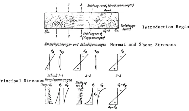
In a beam, loads cause a system of principle tensile and compression
stresses which change in magnitude and direction at different levels of the
cross-section. In general, to obtain the stresses theoretically, an orthogonal coordinate
system x-y is established, which leads to the usual stress formulas<f'i
=
M.y/JandIxy QS / Jb. From.:::r; and Ixy the magnitude and direction of the principa 1
stresses are det ermi.ned , The shear stress r-:xy shows that the principal str e s s e s
do not lie in the directions of the coordinate system, but that they are inclined.
For failure of the concrete, セ「ケ itself does not govern since the
ウセ・。イ stress hypothesis, that is the assumptio2 that failure is caused by maximum
shear stresses, does not apply to brittle building materials as is known. On the
other hand, the principal tensile stresses govern for the crack formation of the
brittle concrete. The principle tensile stresses セ depend on the combination of
moment and shear force. Only the maximum tensile stress at the extreme fibres,
which we call the bending tensile stress, is determined by the moment only because
at the extreme fibres I is
=
O. On the other hand the neutral surface (cr=
0)x
2.
is a fibre where the principal stresses depend only on the shear force; therefore
the magnitude of the shear stress セo in the neutral surface is equal to the principal
stresses, which have an inclination of 45 degrees there. In most cases however,
the principal stresses at the neutral s urf ac e are not the maximum values of the
principal stresses for that particular section, so that セo is neither decisive
for the crack formation nor for the carrying capacity. Usually the cracks start
from the tensile boundary, as do the inclined shear cracks. Only in special cases
(beams with very thin webs, cross-sections with large shear force and small moment),
the principal stresses セ in the neighborhood of the neutral surface can be
de-cisive for the crack formation.
Usually the stress component セ is neglected for the practical bending
theory of beams. However it is present everywhere where outside loads are applied
approximately perpendicular to the axis of the beam, especially in the vicinity
of the reactions and the point loads キィ・イ・セ becomes a compression stress. In
these regions the principal tensile stresses become smaller and are flatter and the principal compression stresses are larger and steeper.
If we go to the combined building material, reinforced concrete, and load the beams so far that cracks occur in the concrete tensile zone (Case II),
then the interior stress distribution is really changed. Ie cannot be derived
theoretically exactly since the interior stresses in Case II depend on the crack pattern and the arrangement of the reinforcing according to size, direction and
distribution. A theoretical treatment of the interior stresses is only possible
with rough approximations.
Generally it is assumed that the neutral surface is the same for shear and bending and that below the neutral surface no concrete tensile stresses occur.
3. below the neutral surface must be constant and that the principal stresses must be inclined under 45 degrees with respect to the longitudinal reinforcing (Fig. 2);
7Q
=
QSO/bJ=
Q/bz.II
These relations have been known a long time. E. Morsch discussed them
in detail and using them derived his well known design rules for the shear reinforcing
for reinforced concrete beams, which he confirmed by numerous pioneering tests. His
rules are based on the truss analogy where the forces corresponding to the principal tensile stresses are carried by the inclined rods while the principal compression stresses are carried by the strips of concrete between the cracks.
Equilibrium of the interior forces computed according to Figure 2)howeverJ
is only then possible if one has inclined rods at 45 degrees spaced closely together
and also shear cracks at 45 degrees. As soon as the cracks deviate from the 45
degree direction and become steeper, as is the case for large stretches of a beam in the region of larger moment and smaller shear forces, then the compression strips
at 45 degrees are not possible any more. Immediately the interior stress relations
in the concrete strips between the cracks must really change. In spite of this,
for inclined rods and approximately vertical bending cracks or for inclined cracks
and vertical stirrups, carrying actions as in a truss are possible. However, if one
has only stirrups as shear reinforcing in the region of almost vertical bending
cracks then no truss action can occur. We know that then the beams carry their loads
as arches or frames with tensile rods; the largest part of the shear force is then absorbed in the compression zone by inclination of the resultant D (Fig. 3), thus
there I becomes large while 'r below the neutral surface becomes almost zer o , Such
carrying actions occur even partly in the case of the relations of Fig. 2. The
carrying capacity of the bending compressive zone is weakened however by a large
4.
For the truss analogy one should note that we have an internally statically indeterminate truss with members that cross several times and with chords stiff
against bending whereby the tensile members are more elastic than the compression
strips and thus show larger deformations. As soon as one considers the compatibility
relations of this truss one finds that the stiffer compression strips must always carry more load than the more elastic tensile diagonals, whereby the chord is stressed
under bending. The compression stress strips advantageously are supported by the
stirrups that surround the concrete cross-section. For full shear reinforcing, the
larger horizontal component of the forces in the compression strips caused the tied-arch action to occur, even in the region of inclined cracks and inclined rods. For this reason cross-section of the tensile rod and thus also the steel stress
of importance. It is obvious that it is important to carryon a large part of
the lower reinforcing rods to the supports and to anchor them there faultlessly. When the beams are less slender, the tied-arch action plays a larger
role, because then the arch or the frame respectively becomes very capable of
carry-ing loads without help of the truss action. From this it follows that short beams
under shear are less dangerous than was to be expected from the truss analogy and
from the magnitude of
10.
"
In 1955 in the Material Testing Laboratories in Zurich, R. Walther (Ref. 1) proved with shear tests the dependency of this tied-arch action of the lower reinforcing rods on the bond quality for the case of shear reinforcing with
stirrups and inclined rods (Fig. 4). In the lower reinforcing rods of all beams
for higher loads considerable tensile stresses were present close to the supports.
For polished round steel the pure tied-arch occurred and the cracks showed no noticeable inclination.
That the truss action does not develop completely even when inclined rods and stirrups are provided for the complete sheas also follows from the steel
stresses measured on the inclined rods (Fig. 5). Before occurrence of the
cracks the stresses lie at ョセイ (n times the concrete tensile stress), but in
Case II after cracking they stay with good bond far under the values computed with
-r
0' even if one considers the action of d ry above the supports.Hence actually in Case II, セo is neither similar to the principal
tensile stress nor to the principal compression stress. This fact must be
con-sidered especially if one investigates the safety against shear failure. One must
say--and following test results will prove エィゥウMMエィ。エセッ is not a suitable criterion
for the safety against shear failure. Anyway in the case of the brittle building
material concrete there is no shear strength in the sense of a property of the
building material. Even for marked shear loading no shear failures occur in the
concrete but separation failures perpendicular to the principle tensile stress.
Usually the compression trajectories are steep arches and the tension trajectories in the reach of the large tensile stresses are very flat.
The design and the type of shear reinforcing according to the rules
specified by E. MHrsch on the other hand always leads to a sufficient safety against
shear failure. Because of this fact, which is confirmed by practical experience,
there would be absolutely no motivation to consider the shear problems again if we did not know that the safety factor against shear failure for this type of
rein-forcing is considerable and often many times too high. Because of the introduction
of the high allowable steel stresses and the ribbed reinforcing rods with much better bond than before, new relations were created>in addition)whose action on the shear
behavior must be proven again with tests. However, the basis for the new studies
are the possible simplifications and savings for the shear reinforcing which will be shown at the end of these articles.
2. Observations About the Present Allowable Limits for the Shear Stress セッG
6.
allowable セo are shown for each concrete strength:
1. A lower limit below which no amount of the shear reinforcing is required.
2. A top limit which may never be exceeded and thus determines the smallest
allowable cross-sectional dimensions of the concrete.
Thus, when the shear stress {- in a beam stays below the lower limit then the shear reinforcing is left to the designer without computed proof.
Slowly it has come into use that especially for plates in this region absolutely no shear reinforcing is used while one uses very few stirrups for beams.
Up to now nobody has proven whether sufficient shear safety exists for all possible types of loading with this type of reinforcing, especially when the
main reinforcing is only partly carried on up to the supports. Tests on this,
therefore, were urgently required. They show that セoG under the failure load for
B300 and reinforcing steel IIIb, can lie between 14 and 94 kg/cm 2, while the
allow-able /(0
=
10 kg/cm 2.The top limit is set rather low, for example for B300 at 20 kg/cm2. Thereby one had in mind the principal tensile stresses and the tensile strengths
or the somewhat higher assumed "shear strength" and i t was further believed that
because of this low limit of セo the beam would stay crack-free in the shear span.
Thereby was forgotten that the principle tensile stress for a positive moment al-ready is larger a bit below the neutral surface and that it quickly exceeds the tensile strength of the concrete in the extreme fibres in all cases and that cracks occur there.
It is difficult to understand why the allowable stresses are limited according to the tensile strength of the concrete for the fibres in the neutral surface when we do not do this for the fibres lying below this and there simply
assume a cracked tensile zone. This assumption is also a basis for the design of
.,
! ,
sufficient reinforcing that they stay very small under working load, then we mLst also allow the same privilege for the fibres that lie somewhat higher and there also allow that the tensile stresses and respectively the tensile forces are givea
a 3citable reinforcing. We will show that for suitable reinforcing the shear cracks
are less wide than the bending cracks. However, in thin webs for ample protection
of エィセ iLclined tensile forces by inserted steel, not the concrete tensile strength
but the concrete compression strength becomes governing? because the concrete strips
between the shear cracks fail under compression. In one of the following tests with
beams of B300 failure in the web by inclined compression was reached for a load
that corresponded to セo
=
180 kg/cm2 and thus 9 times the allowablette allowable セo values can be put higher than up to now.
セ
I O· Hence
In the earlier choice of the top
to
limits, constructionconsidera-tions also played a role, without doubt. セo values are, as a result, such that for
common beams the webs must be chosen sufficiently thick that it can contain the reinforcing easily and that the concrete in the webs can be poured and vibrated
without difficulty. Today these points of view are not valid any more in most cases.
Especially in prefabrication of beams, thin webs are used where the concrete between
the steel forms is compacted with vibrators on the outside, In France where one
is not hampered by the low 1'0' for example, it has been proven, that for beams with
long span lengths, very thin webs can be poured faultlessly. For a sensible design
of beams where the shear forces are very high, compared to the moments especially
for highly loaded box beams, as for example first floor walls of high-rise 「オゥャ、セョァウ
with high supporting loads, again and again the low セo limit has been considerable
obstacle in the later years. There were cases where beam webs or lower flanges,
must be over one meter thick, entirely because of the allowable "]- 0 although 30
to 40 centimeter thickness was sufficient and would not ィセカ・ lead to difficlllties
8.
As a pre-requisite for an increase of the allowable セoG however, the
influence of the type of reinforcing and the direction of the reinforcing on the
inclined compression stresses must be investigated so that the top limit of JrO'
as long as one wishes to stay with this computed value of the shear stress, is determined such that a sufficient safety is always available.
The following tests therefore must also consider the question of the
top
--r
0 limit.3. The Question of the Future Design According to Shear Failure Load.
The above considerations show already that the present design of our
reinforced concrete beams on shear. based on the computed shear stress セo with
two allowable セo limits cannot be satisfactory. The tests described later on
showed this especially clearly since the computed セo under failure loads for
example for concrete strengths B300 varied between 14 and 180 kg/cm2. Today we
know that the shear failure safety, if no shear reinforcing is present, in spite
of the low bottom セo limit, is not sufficient in many cases and that in other
cases. with or without shear reinforcing, the safety against shear failure becomes much larger than is actually required.
The bending failure loads can be computed beforehand rather precisely today and many countries have already changed to design for bending according to the ultimate load method, thus according to a load, Pkr• at a critical deformation
or the failure load, PU, with a certain safety factor. This step is also intended
in Germany. However, it is very unsatisfactory if for one beam we must use two
different design methods, the ultimate load method for bending and allowable stresses
for shear. For that reason there exists a pressing necessity to learn to compute
the shear failure load somewhat precisely beforehand. The shear failure of beams
of reinforced concrete or prestressed concrete was the subject of much research,
9. that not only the shear force, Q, by itself governs, but that the complete force picture in the section, represented by N, M, Q, for bending without longitudinal
force and preferab1v the ratio セ deserves a decisive meaning as a shear failure
J Qh
criterion. Thereby the carrying capacity under shear is determined by a moment,
the "shear fai lure moment"
Msu.
M a
To some extent this ratio Qh' which corresponds to the ratio
h
for pointloads has been labelled the shear span length, which is unproper since it is a
"
dimension-less quantity. A. Rusch chose the expression shear slenderness, which
is better. We will here speak simply of the moment-shear-ratio or M ratio to avoid
Qh this uncertainty.
With this ratio M the reduction of the strength of the bending compression Qh
zone ever the shear crack can be expressed, since there not only セク acts but
at the same ーッゥョエセN thus a two axial stress condition exists, or expressed
differently, the compression resultant D is inclined because of the arch 。」エゥッョセ
"
with vertical component Dv or LQ as already shown by Morsch.
R. Walther used these relations in his thesis (Ref. 7) in a proposal for
a stear failure theory, which is marked especially by the fact that a deformation condition for the shear region was drawn up which considers the influence of the
amount of reinforcing and its bond strength. The compatibility of the deformations
plays a role in all our beams and influences the interior forces. For bending)the
、・セッイュ。エゥッョ condition gives us the location of the neutral surface, for bending with
shear force similar conditions must hold. The shear failure theory of Walther
likewise is based on equilibrium and compatibility conditions with which the actually reduced neutral surface height as compared to bending, in the shear zone is determined.
These thoughts appeared so enlightening and logical to the senior author that he, together with R. Walther, set out to conduct tests to build up this shear
10.
are primarily arranged such that a single parameter for the shear failure theory could be obtained.
セa」」ッイ、ゥョァ to the present conditions the shear failure theory of Walther
will be pub Lis'he d directly in connection with the following test results. It
" '
gllows design oセ the basis of ウセ・。イ failure load and therefore is linked sensibly
to cセセR de si gn fdr dセ、ゥョァN
4. Test P:a::1
イセイウエ of all the test plan contained several series with simple rectangular
beams with'Jlt shear reinforcing in order to explain the variables especially importart
for the shear failure theorY,such as セ・ゥョヲッイ」ゥョァ ratio, bond}and type of loading.
For that purpose, beams without shear reinforcing are especially suited, because
the different magnitudes of influence can be investigated somewhat separately. In
addition to that, such tests are very necessary from the point of view of the
pre-sently so numerous massive plates without shear reinforcing. The different influence
of the moment-shear-ratios was studied in numerous tests with changeable セィG
Also the influence of the absolute magnitude of the beams must be che cked
with these tests, since it is connected to the bond strength.
"
E. Morsch already investigated several types of shear reinforcing of
stirrups and bent-up rods and came to the conclusion that distributing of the forces that must be picked up approximately 1/3 to stirrups and 2/3 to inclined rods gives
the best solution of the shear safety. Since セィッウ・ tests, there セB .: t hat
show that vertical stirrups by themselves approximately give the same failure lead
as the mentioned distribution (Ref. 8). Also in the U.S.A. it was proven repeatedly
that stirrups by themselves are quite favourable, which can add to a simplification
of the shear reinforcing. Today this possibility is especially important since the
ratio of wages to building materials has gone up. Correspondingly, tests on
11. whether a better shear carrying capacity can be achieved with bent up rods, vertical or inclined stirrups and which part each of these types of shear reinforcing adds to the shear carrying capacity.
It is known that in many cases the complete coverage of the shear forces
"
according to Morsch by stirrups and inclined rods, thus the so called complete shear
protection, is not necessary. The shear failure theory will make it possible to
ascertain the required amount of shear reinforcing for a certain safety. Numerous
test results published in this article will be quoted to confirm the new theory. From several tests of other research workers (Ref. 9) it appears that the shape of the cross section has a noticeable influence on the shear carrying capacity. The shear failure theory of Walther indicates that the width of the compression zone
is more important than the web width. A few tests were carried out on this question
also.
From the point of view of rewriting DIN 1045 it was very important for the authors to carry out tests, to determine the top allowable limit of the shear
stress セoG according to the points mentioned in Section 2, as a function of the
prism compression strength of the concrete. Because of the urgency of this question
the information on these tests is given priority.
Firstly only short duration tests under statical loading were carried out because the influence of long duration load or a variable load is sufficiently known from numerous other tests, so that the safety against disadvantageous actions of those influences can be obtained from the known reduced values for an order of size.
It was preferred to carry out these tests with Rippentorstahl because
this is used mainly in construction in Germany. In the case of stirrups,
Rippentorstahl IIIb• smooth round steel I and smooth round steel IIIb were compared, because for stirrups quite often smooth steel is still used.
12. For the concrete)B300 and B225 were chosen because these concrete strengths
are used mainly. A fundamental reduction of the concrete strengths for tests to
2/3 of the theoretical value, as is promoted so often presently, the author con-sidered unsuitable here, because the determination of the actual safety becomes more
difficult. Such a reduction is justified where the failure of the steel governs and
the concrete serves as a agent for the behaviour of the steel, thus for example for the anchorage of steel but not however where the failure of the concrete itself determines the carrying capacity, as is the case in most of the following shear tests. The spread of the concrete strength is considered for design by a higher safety
factor in the form of a reduced concrete strength, which will also allow the influences
of long duration load, fatigue, construction and such to be included. It must not
be overlooked that different concrete properties as for example, shrinkage, plasticity, or the ratio between tensile and compression strength are improved by reduction
of the concrete strength of the test beams under certain circumstances.
The following test results are limited to the important data, results
and conclusions. The complete test results will be published in the research
II. TEST RESULTS
1. TESTS FOR HIGH SHEAR STRESSES
(December 1961, Pages 280-290)
1.1 The Test Beams
1.11 Shape and Design - The top shear stress limit
セo
=
セコ
which leadsto destruction of the concrete by inclined compression, was expected in a magnitude that corresponds approximately to the compression strength of web, thus approximately
0.6
セー
or about 150 kg/cm2 for B300. To achieve failure because of inclinedcom-pression, the test beams must be constructed such that under working load, very
high shear stresses of approximately 65 kg/cm 20ccur. Such values can be produced
for box beams, however, there the vertical stresses
<ry
disturbed the desiredtrajectory picture. Therefore T-beams were chosen with a wide top flange ascompression
chord and a closely reinforced tension flange to prevent an early destruction under
bending. The web was kept comparatively thin in comparison to these flanges, without
interfering with the regular installation of stirrups made up of two sections. Thus
resulted the beams shown in Fig. 6 with somewhat unusual cross section which should not be considered as examples of beams for practical purposes; the 10 cm thick web must be considered much more as a model of a thin plate under high shear stress or a web in a long beam with box cross section.
Also it was desired that over a large distance the possibly principal stresses would be practically equal and at the neutral surface inclined under 45 0. This can be achieved most simply by symmetrical two point loading, whereby the distance between the support and load in this case was equal to three times the
オウセ「ャ・ height, to obtain a sufficiently long zone free from load introduction
disturbances.
14. These large beams designated with Tl and T2 were constructed and tested. They were different in arrangement but not in amount of shear reinforcing.
1.12 Web Reinforcing - The web of beam T l is reinforced with vertical
stirrups 12 rom spaced 8 cm apart. The stirrups cross-section corresponds to complete
"
shear protection according to Morsch for a working load of about 100 tons. At the
top the stirrups are bent transversely in the flange and at the bottom they are bent t9 the outside to surround part of the longitudinal rods, thus they are at top and
bottom anchored faultlessly. The diagonal stirrups were connected to the longitudinal
rods with wire only and thus not welded. Obviously the diagonal stirrups do not
slide with good bond of the longitudinal rods and with sufficient shear reinforcing. In the right half of the beam ribbed Torstahl was used and in the left half smooth
Torstahl. The latter were manufactured specially by HUttenwek Rheinhausen and in
fact were formed so cold that practically the same stress-strain curve occurred
as for ribbed steel. Thus for the stirrups only the quality of the bond was changed
in both beam halves.
The web of beam T2 had inclined stirrups, 12 rom of reinforcing-steel IIIB
spaced 11.2 cm apart with an inclination of 450 and as above, designed for complete
shear protection. The stirrup shape is the same as for beam T l. Again in the left
beam half smooth rods and in the right beam half ribbed rods were used. In the
region between the applied loads the inclined stirrup web reinforcing was abandoned
completely.
It should be noted that no additional longitudinal reinforcing was used in the web although without doubt they must be installed for the practical case. This was done so that the compaction with submerged vibrators was not unnecessarily hard in the thin web and also to study the action of the stirrups alone.
1.13 Supports - At the beam end the unfavorable case of a support from
action of セ y in the zone of the support was reduced and the anchorage of the
IS.
main reinforcing rods was tested under unfavorable conditions.
As a result, the 1 m wide and 25 em thick transverse beams at the supports
are stressed highly under shear. Since the span length is small compared to the
height we have a pure shear case. Incidentally it could be shown here again that
for this type of shear it is better to use horizontal reinforcing rods in several
layers together with a few stirrups and not bent-up rods under 600 as is advised
frequently. For this, compare the tests of Leonhardt-Andra on the divided anchorage
of concentrated stress cables (Ref. 10).
1.14 Chord Reinforcing - As tensile reinforcing, 16 - 26 mm
0,
rippentorstahlIIIb rods were installed close to each other in the bottom flange and all rods were
carried straight to the beam ends. Bent-up rods would have been a disturbance in
the thin webs. At the cantilevered ends it was observed whether slip occurred which
generally was to be expected for the very small distance of the end plane of the
beams from the support line and for the type of support. Since anchorage failure was
undesirable on the other hand the ends of the rods were threaded and an anchor plate
installed. However, the anchor nuts had spacing between the anchor plates and were
only to be tightened in case of necessity. The lower reinforcing is surrounded
with stirrups, セ 10 mm spaced 16 respectively 22 cm in transverse direction. The
15 cm thick compression flange had the same transverse reinforcing and a weak longitudinal reinforcing.
1.15 Computed Values of the Allowable Working Load, Bending Failure Load,
Stresses, etc.
-Cross-section values: Fe
=
85.0 cm2 (160
26 mm BSt IIIb)x
=
34.1 cmOwn weight: g
=
1.05 tim (including loading structure)16.
Allowable working load: Mg+p 122.6 tm (based on DIN 1045 with
a llowab 1e <::1b
=
90 kg/ cm2)セ
=
117.9 tmAllowable utilizable load: 2P
=
94.3 tQp 47.15 t
Q
g 3.15 tQg+p
=
50.3 tCombined working load: 2 Pkr + G セQPP t
Carrying moment when yield point reached in tension chord:
whereby
セォイ
= FeA .
2 . Zc5b -:::::
160 kg/ cm285 x 4.0 x 0.75 255 tm
Corresponding carrying load: 2 P セQYQ t
Stresses under working load (computed according to DIN 1045) Bending stress at extreme fibre:
a llowab 1e セ
=
90
kg/ cm21916 kg/cm2 (allowable セ
Shear stress at support:
7;
=
セ
=
67 kg/cm 2bo
Zallowable
/0
=
20 kg/cm 2Design of the stirrups:
Shear force : T =
%
b
oL
=
67 x 10 x 100=
67 timBeam T1: vertical stirrups T
FeBU = allowable セ・
=
672.4 27.9 cm2/m17.
Beam T2: inclined stirrups
required FeBU 672.4 .r-r:= 19.8 em ;2
v
"-o
12 BSt III b, e=
11.2 cm, available Fe(Additional information computed by J.G. MacGregor
20.0 cm2 I Q 3,629,000 cm4 51,490 cm3 Ytop
=
29.8 em Ybottom=
60.2 cm)1.16 Construction of the Beams - The beams were poured upside down, thus
with the tension flange at the top, whereby the concrete for the web was poured
between the reinforcing rods through the holes for the vibrator. Thus, the main
reinforcing represented the unfavorable case of top steel.
To pour the web as accurately as possible with respect to dimensions they
were formed with [350 steel beams. On the other hand this meant that the side
supports could only be added later on whereby the construction joint was just in
the regiun of the highest shear stresses. Thanks to suitable additional reinforcing
this did not lead to damage.
1.2 Building Materials
1.21 Steel - The stress-strain diagram of the セ 26 mm セ rippentorstahl
of the longitudinal reinforcing and of the stirrups, セ 12 rnm, is shown in Fig. 7.
The cross-sectional area of the stirrups, determined from the weight, was somewhat less for the smooth rods than for the rippentorstahl (see TABLE I).
TABLE I: Properties of the reinforcing steel
Type of Steel No. Measured
セNR
セ
E'lorrgat Lonセ cross-sectiona 1 at failure E rnm area rnm2 kg/cm2 kg/cm2 % kg/cm2 Smooth torstahl 12 109 4270 5490 14.8 2.10 x 10⁶ (60,900psi) (78,000) 106 Rippent rstahl 12 116 4350 5470 17.0 2.10 x (62,000) (77,900) 106 Rippentorstahl 26 529 4740 5600 1) 2.08 x (67,"500) (79,900)
18. 1.22 Concrete - For both beams a concrete strength B300 at age of 28 days
was planned. To keep the increase in strength during the three days of the test as
small as possible an early strength portland cement 2475 was used.
The aggregate, washed Rhine gravel, was divided in 4 grain sizes, 0/3,
3/7, 7/15 and 15/30 rom. Quartz powder 0/0.02 mm increased the fines. The mortar
proportion 0/7 mm amounted to 71%. The composition of the concrete and important
technilogical data are summarized in TABLE II.
TABLE II
PROPERTIES OF THE CONCRETE Beams
Cement Water
Quartz powder Water-cement ratio with respect to cement and quartz powder Slump test
Air -pore ratio
Weight of 1 cu. meter of compacted concrete
at day of test (age 28 days)
(bending tensile strength)
T l T2 230 kg/m 3 230 kg/m 3 199 liters /m3 207 liters/m 3 118 kg/m 3 118 kg/m 3 .57 .59 35 cm, 40 cm. 3.0% 2.6% 2250 kg. 2250 kg. 298 kg/cm2 269 kg/cm2 (4250 psi) (3840 psi) 40 kg/cm2 36 kg/cm 2 (570 psi) (512 psi)
The cube strength
P
w was determined from 20 test cubes 20 x 20 x 20 cm.and the bending tensile strength
P
bz was determined from prisms 10 x 10 x 53 cm.The stress-strain diagram of the concrete shown in Fig. 8 was obtained from two prisms of 10 x 10 x 53 cm.
19.
1.3 The location of the points where measurements were taken and the method of
measuring
The large dimensions of the test beams allowed extensive measurements to
determine the pattern of stresses and deformations. For each beam. measurements
..
were taken at approximately 350 places to which during the loading were added
approximately 300 locations for reading the crack widths at three elevations. To
keep the duration of each load increment short, 12 assistants were used for the readings.
Detailed information about the location and meaning of the single measure-ment points, dispensed with here on a plan, can be obtained later from the complete test results mentioned in the beginning.
1.31 For the stirrups the elongation was obtained with plastic elongation
measuring devices and strain gages. For the measurement of the plastic elongation
over a gage length of 20 em, measurement points were used for each beam half for Tl at 10 stirrups each at three locations and for T2 at 8 stirrups each at three
locations. The gage points were drilled in the stirrups before they were placed
in the concrete and little tubes filled with paraffin were applied. After pouring
of the concrete the gage points could be reached by the gages by removing the
parraffin. Accuracy was approximately
±
0.02 セooNOn 6 stirrups 4 or 5 strain gages (in beams T l and T2 respectively) were
glued in milled slots of width of 1 rom (in the reinforcing rods themselves) and
covered with araldit for closure and electrical insulation. Accuracy was approximately
+0.01
crfoo.
1.32 On the chord reinforcing, strain gages were installed in slots, 2
each at the quarter points and in the neighorhood of the support and 4 each in the middle of the beam.
w.
half 3 rosettes with 4 rays with glued-on measurement plates were installed for
measurement of elongation. Because of the expected disturbances because of cracks
the smallest available gage length of 5 cm was chosen. For the analysis only the
compression direction inclined under 450 gave usable results.
1.34 Likewise the elongations of the concrete in the compression flange
and in the tension chord were determined with gages over the entire length of both
chords with gage lengths of 20 and 50 cm. Between and very close to the loads the
transverse distribution of the longitudinal elongations was also measured.
1.35 The deflections were measured with a precise level. Accuracy was
approximately ±D.l mm.
1.36 The formation of cracks on the concrete surfaces covered with chalk
were followed accurately with a magnifying glass. The crack widths were measured
with a microscope (reading 1/100 mm) at three elevations: at the elevation of the
main イ・ゥョヲッイ」・ュ・ョエセ at the transition from tensile chord to web and in the middle of
the web. The cracks were numbered in the order of their occurrence (numbers in
circles in Figs. 10 and
lU
and their ends marked with the load in tons present atthat time.
1.37 At the anchorage the cantilevered ends of the main reinforcing rods
were tested for slip with a few dial gages. It was shown for sure that the anchorage
stayed in full effect up to failure of the beams.
1.4 Loading
Because of the many measurements a beam test lasted for three days. The load was applied twice in increments of 20 tons each, and the load was taken
off in between. Since the measurements lasted approximately 45 minutes for each
loading, a time influence on the concrete deformations, especially for higher
loads, therefore could not be avoided. During all pauses, and also during the
21. MAN testing machine.
1.5 Test Results
We want to consider the test results of both beams T l and T2
simultane-ously because useful information can be obtained thatway. The crack patterns
after failure are showp. in Figs. 10 and 11.
1.51 Failure Loads
Beam Concrete Fai lure Max.
セ
at fai lureStrength Load Test Converted
/31#
eP
kg/cm 2 toBw
= 300kg/cm2 t
298 160 111 112
269 232 160 178.5
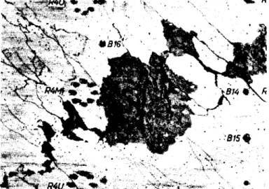
1.52 The Causes of Failure - As expected for both beams the concrete failed in the web under the inclined compression, where the concrete scaled off
at the surface and fell to pieces in thin segments (Fig. 12 and 13). Indications
of buckling of the concrete strips could not be determined and was also not ex-pected since the thin web was held by the high tensile stresses of the stirrups. Since the failure load for T2 was higher than for Tl in spite of the same cause of failure the stress of the concrete in the webs for vertical stirrups must be larger than for inclined stirrups as was confirmed by the following measurement results.
1.53 The Inclined Compression Stresses in the Web - From the many concrete
elongations measured on the web, with the help of the stress-strain diagrams (Fig. 8),
the compression stresses under approximately 450 between the inclined cracks could
be obtained. In Fig. 14 the average values, outside the load introduction zones,
are shown as a function of the load. The measurement locations which were not
disturbed by cracks and which were used to give the average values are shown in Fig. 14.
22. We find confirmed that the inclined compression stresses are much larger for vertical stirrups (T 1), approximately 1.5 times, than for inclined stirrups. This ratio corresponds somewhat to the ratio of the failure loads.
For both beams, at failure, inclined compression stresses セ (as
principa 1 compre s sian stress) in the order of the prism compression strengths were reached:
.8513'# = 253 kg/cm2, average <7I"I approximately 220 kg/cm2
T 2:
f3p
=
.85J3
tAl=
228 kg/cm2, average<7Ii
approximately 230 ォァO」ュRセ ...This proves, that the inclined concrete strips are more or less under pure compression and that the stresses obtained from the elongations at failure
correspond closely with the strengths. This is important, because the magnitude
of
c1Ii
deviates considerably from values computed according to the truss analogy.In Fig. 15 the stresses and the internal forces are derived that follow from the equilibrium conditions under the assumption that the chord forces are horizontal and that the shear force accordingly is taken care of in the web only. Subsequently the inclined compression stresses for the case of inclined stirrups
under 45 degrees were equal to セL for vertical stirrups, however, 2 セoG thus twice
as large. These theoretical values are also shown in Fig. 14.
It is interesting that the measured inclined compression stresses in
the case of inclined stirrups lie approximately 50% higher than the
1-
0 values,while the stirrup stresses, as we will see later on, reach only approximately 80%
of the corresponding computed values. Thus we find, as mentioned in the beginning,
that the stiffer compression strips are stressed more than the flexible tension rods.
These somewhat unexpected conclusions still need an explanation,
since at first they seem to be contrary to the customary equilibrium conditions.
23.
Next one must consider that the inclined compression stresses shown in Fig. 14
are in fact average values of a complete shear span, but that each measurement point
used for the average value lies in a zone undisturbed locally by cracks. Between
the branches of a single crack, where measurements were not possible, there is no
doubt that the inclined compression stresses are smaller. With it also the combined
average value of <r.[I over the complete shear span becomes less than the value showTI. For beam T l with vertical stirrups this could be the principal reason for the
difference (approximately 15%) between the computed and the measured cr.rI' This
influence is also present for TZ' and in fact much stronger, because of the greater
number of shear cracks; however here also the stirrup stresses playa role. From
Fig. 15 (left below) it can be seen that the vertical component of D and
Zs
to-gether must be equal to
Q.
Since the measured force ZQ only amounts to 80% of theo
theoretical value, the difference of 20% must necessarily be carried by the inclined
compression strips. Since the resultant of D and
Zs
then deviates from the vertical,merely means that the tension chord is loaded somewhat more and the compression chord
however is loaded somewhat less than corresponds to the theory. For vertical stirrups
(Fig. 15 right) the stirrup stress has no influence on the inclined compression
stresses. Therefore the differences between the computed and the measured values
for T l are smaller than for T2.
1.54 Stresses in the 3tirrups - First we consider the average values of
the stirrup stresses which can be obtained from the elongations in the central
reach between support and load (Fig. 16) and compare them with the stresses computed according to the classical shear theory.
whereby
-;-- -;-- _ 0
l.oo'eB - セBGb
".,.. FeB
FeB
=
cross-sectional area of a stirrupa
=
stirrup spacing in the direction of the beam axis24. The stirrups, each with three locations for elongation measurements, used to obtain the average value are sketched in Fig. 16.
For both beams the stirrup stresses up to failure load stay clearly under the computed values, namely for beam T l around 750 kg/cm2 and for T2 at approximately
600 kgicm 2. For the working load this corresponds to a difference of approximately
30% and 25% respectively and approximately 20% for 1.7 times the working load. At
the failure load of beam T l the stress of the vertical stirrups amounted to an
average of 3300 kg/cm 2; for the failure load of T2 the inclined stirrups were stress-ed to an estimatstress-ed value of 4400 kg/cm 2, while the theoretical value lies much
higher, namely at 5700 kg/cm2. The pattern of the stress curve shows that the
stirrups were already somewhat in the plastic zone.
When the stresses in the stirrups stay under the computed value this is only possible when, even for such a strong shear reinforcing, a part of the shear
force is still carried by the frame with the tensile rod action. This is confirmed
by the increased stresses in the tension chord and in the compression strips. The inclined stirrups or ribbed steel show a somewhat higher stress than those of smooth steel, while for the vertical stirrups a reversed tendency was
observed. These differences can be attributed to certain coincidences of the
crack formation but also to the fact that the smooth stirrups withdraw somewhat from carrying the force by a small slippage or that these rods have a somewhat
smaller cross-section than the ribbed ones. For the inclined stirrups mainly the
bond and for the vertical stirrups mainly the smaller cross-section accounted for the different behavior.
In Fig. 17 the stress pattern of a few stirrups is shown with small
deviations smoothed out. The locations for the measurements are marked with 0
(top), m (middle) and u(bottom). The solid lines refer to the ribbed stirrups
and the dotted lines the smooth stirrups. Accordingly the inclined stirrups carry
25. stirrups which, as we will see later on, is also shown clearly in the deflection
and the crack formation, In the lower load increments the vertical stirrups are
under compression, In the middle of the shear span, a stress decrease from below
to above is seen in all stirrups, The decrease in stress is small, however, so
that the anchorage of the stirrups, even for ribbed rods. above and below without question must be insured against slipping as in the test either with hooks or by perpendicular bends.
1.55 The stress in the tension and compression chord - Next we consider
again the theoretical chord forces in Fig. 15 for the different trusses and we see
that in the shear span (Q active) because of the different diagonal forces,
different chord forces are developed for vertical sections. Only for stirrups at
M
450• may we expect equal chord forces D
=
Z=-- ;
for vertical stirrups D, Z andQ differ. The horizontal tension force in the web. mentioned in the book by E.
Rausch (Ref. 11), キセゥ」ィ had to be taken by horizontal web reinforcing, was only
present there because arbitrary equal chord forces were assumed. This however
is impossible, 「・」。セウ・ the fibres at the neutral surface did not elongate and a
horizontal reinforcing therefore is not stressed under tension. The equilibrium
condition is satisfied much more by the difference between D and Z. which came to
light clearly in beam T l, In the region of pure bending (Q
=
0), between theloads P, again both the chord forces must be equal but opposite,
The readings show that the boundary stresses at the compression chord (Fig. 18) decrease faster towards the outside than was to be expected from the
bending moment curve. In the neighborhood of the support in the compression chord
even considerable tension stresses and cracks occur, which can be attributed to the arch action. which shows itself much better for vertical stirrups than for
inclined stirrups. Clearly it is shown that in the undisturbed shear span the
horizontal compression force for vertical stirrups is smaller than セ by approximately
z
Q
26. those for T2, can be explained from the fact that the compression zone for Tl is decreased by the shear cracks that penetrate beyond the bending-zero-line (see Fig. 10).
In Fig. 18 are also shown the elongations measured across the cracks at
the tension chord. They are corresponding to Fig. 15, larger in the shear span
for T l than for T2. Accordingly vertical stirrups decrease the load in the compression chord in the shear spans and increase the load in the tension chord.
For construction members under shear, for which the inclined compression brings on the failure, inclined stirrups are to be advised according to 1.53, while for the many cases where the shear failure occurs because of destruction of the compression zone, vertical stirrups with their action to decrease the load in the
compression chords, can be advantageous. Noteworthy are the peaks in elongation in
the tension chord, clearly visible under the loads for Tl. They can be attributed
to local bending deformations because of the vertical compression of the web HMセ
compare Fig. 17, Stirrup 3); in the case of inclined stirrups they are relieved
by the stirrup forces at these points. Also one must imagine two opposite compression
strips between the loads that contribute to the peak and then at
L
reduce the2
tension force to the value M which are somewhat equal for Tl and T
2·
,
z
In Fig. 19 the compression stresses in the middle of the beam are shown as
a function of the load. The difference between Tl and T2 is already confirmed. On
the other hand, it must be considered why the measured values are above the computed ones, when the opposite could be expected from statics, for example with respect to the equilibrium of the internal forces for non-linear stress distribution above
the neutral surface. Time influences can hardly be governing since the plastic
deformations for prisms and the beam tests were approximately equal. The elongations
over the width of the compression flange were also somewhat equal. We suspect that
27.
derived from a prism compressed in the center differs from the behavior of a bending
boundary zone. At failure the maximum €b averages at about only ROセャ while for bending
in a rectangular section values up to 3%oand more can be reached. The stress-strain
diagram for the extreme fibres of the bending compression zones can run flatter
than for the case of the prism tests. The bending stresses computed from the prism
test are then somewhat too high. However, this suspicion must still be proven.
The highest compression stress was with approximately 225 kg/cm2 for beam T2 close to the compression strength so that the bending failure was not very far from the shear failure.
The shear stresses in the longitudinal reinforcing in the middle of the beam at the quarter points, and in the neighborhood of the supports are shown in
Fig. 20. The values in the middle of the beam for both beams correspond closely to
the computed values. At the quarter points, thus in the shear span, the difference
as expected according to Fig. 15 shows clearly. For beam T2 the measured stresses
correspond to the values computed from Z
=
セ,
while for T l they correspond approximatelyz M
to Z
=
-z セ2 Immediately next to the supports the difference disappears. The
compression strips of the frame are already supported on the tension rod before the support whereby the shear forces partly through the stirrups are guided again to the
compression chord. The steel stress at failure was 3600 kg/cm 2, in T l and was estimated
at 4900 kg/cm2 for T2' thus for T2 we were close to bending failure.
1.56 Cracks - For both beams the cracks in the shear zone extend over the
complete web height almost exactly at 450 and only transfer to vertical bending
cracks in the tension chord (Figs. 10 and 11). Because of the side supports the
in-clined cracks continue up to these supports and vertical compression stresses, セL
because of the reaction,arehardly noticeable in the crack pattern. Superficially
no difference is to be seen between the cracks for inclined or vertical stirrups. However, as soon as we consider the sum of the crack widths measured in the middle
28. of the web (Fig, 21) a large difference in the action of both stirrup directions
is shown: the crack widths for all load increments are three times as large for
vertical stirrups than for inclined stirrups, Smooth and ribbed stirrups gave
almost equal crack widths; only for very high loads of beam T2 did cracks for the smooth stirrups become clearly wider.
In Fig, 22 the maximum and the average values of the shear cracks in the middle of the web are compared with those in the tension chord between the loads. Accordingly the shear cracks for inclined stirrups are generally finer than the
bending cracks while the relationship is reversed for vertical stirrups. For
in-clined stirrups the average and maximum crack widths measured under working loads are 0.03 and 0.9 mm respectively, far under the amounts considered safe in
bend-ing tension zones. Even for vertical stirrups, the corresponding values, of 0,10
and 0.24 mm, lie still in the 'allowable" range. Thus in both cases we have to do
with small crack widths in the web so that such high shear stresses in reinforced
concrete beams as considered from the point of view of the cracks, are safe. We
will see that thick bent-up rods in thick webs can give large shear cracks. Thus
distributed reinforcing chosen here, is a condition for the observed favorable behavior,
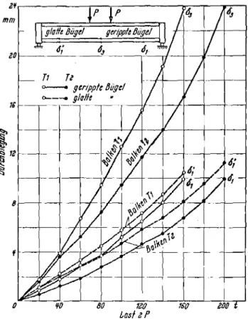
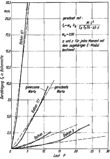
1.57 Deflections - According to the given explanations it is
understand-able that for vertical stirrups larger deflections were measured than for inclined
stirrups. The difference amounts to approximately 35% in the middle of the beam
and in the top load increment even up to 45% (Fig. 23).
The deflections 01 and 01" at a distance of one meter from the support
shown in Fig. 23, show that ribbed stirrups gave smaller deformation than smooth ones, the difference being more pronounced for inclined stirrups than for vertical ones.
29.
showed, even for the highest loads, only single fine vertical bending cracks, and no inclined shear cracks, which can be attributed to the suitable reinforcing with
horizontal and vertical stirrups mentioned in the beginning. This is also the
basis therefore that the longitudinal reinforcing, in spite of the supports at the sides of the beams and in spite of short anchorage length, did not show any slip. Therefore the nuts, installed at the cantilevered rod ends for cases of emergency, that were not tight up to the anchor plate did not have to be tensioned.
1.6 French Tests for High Shear Stresses by l.R. Robinson
In 1960 l.R. Robinson (Ref. 12) carried out tests with 9 beams to
deter-mine the top shear stress limits. The beams had the dimensions shown in Fig. 24
with only a 6 cm thick web and were loaded in the left quarter points with a single
load. At the supports and at the load points the thin web was stiffened with 8 cm
wide ribs, which had as a result that the vertical セyG compression stresses
because of the force introduction in the web, hardly acted. Because of the load
position, a low moment shear ratio of 2 occurred at the left and at the right the ratio was 6.
The reinforcing is shown in Fig. 25; it is in so far uncustomary since the stirrups consist only of one rod that lies in the middle of the web and is
anchored at the ends with hooks (hook diameter
50,
hook end= 50).
These hookslie in longitudinal direction and partly overlap each other and surround the
transverse reinforcing which was installed for each second stirrup. The transverse
reinforcing consisted of a closed ring,
セX
rom, which goes around the longitudinalrods in the tension chord and thus is very strong. The results obtained with this
uncustomary web reinforcing is very educational.
The longitudinal reinforcing consists for all beams of two smooth rods,
セ 40 rom, SrI, with large end hooks and closed transverse reinforcing in the
30. The stirrups consisted partly of smooth Stahl III (denoted DyR), partly
of non-ribbed Torstahl (T), vertically in beam N, and inclined under 450 in beam I.
They consisted of
0
セNLセ[ fc: ""'ive beams and of 10 mm for four bb.:-,S, whereby thestirrup spacing was chosen such that there was an approximately equal shear reinforc-ing ratio, which should lead, for the assumed failure load of 30 tons, to a stirrup stress in the order of magnitude of the yield point (approximately 4000 kg/cm2),
The classical method of computations with n
=
15 gave a neutral surfaceheight of x
=
20 cm and an internal moment arm of z 31,4 cm so that for P=
30tons a steel stress in the tension chord of 2000 kg/cm2 existed, Thus the tension
chord reinforcing was only stressed half as much as the stirrups, The test results are summarized in Table III,
For the first beam NR8 the concrete strength amounted to only 182 kg/cm2
so that the failure load was very low, For the other beams with vertical stirrups
the failure occurred because of the inclined compressions in the web, whereby the inclined compression stresses reached approximately the value of the prism strength,
i.f one assumes again that the inclined compression stress for vertical stirrups is
given approximately by セi
=
RセL For sufficient concrete strength a failureload was reached for which the short stirrups showed a computed stress of 4000 kg/cm2.
For the tests with the inclined stirrups the web did not fail but rather
the concrete in the compression plate, although shear stresses セ with magnitudes
of from 156 to 179 kg/cm2 were reached for B240 to B320 concrete, and the computed stirrup stresses reached were 5300 to 5800 kg/cm2, and thus lay above the nominal yield point,
Because of the large difference in concrete strengths, the influences of different diameters and profiles of the stirrups unfortunately could not be obtained simply,
Table III - Summary and Analysis of Robinson's Tests
Computed !
Shear Reinforcing Measured Values Shear Stresses Stresses
at fai lure, I I
,
I eo -l,jI
C1l '+-l C1l CIl c: I-l 0 I-l iMャセI
''''"
セ ::l ::l''''"
u u U ...-l C1l...-l '+-l C1lI
tll C1l''''"
セGセ I-l 0... I-l ;v -l,j U I tf.l U r.z.. セイNコNN«
- IIZl Abllaod l'R p. Bruch.. ') 2 T. I) r••Rbelm
I
セN
"or"i
I'l')' fl.. art Q t: eretecnilS a. a.
Vcnueh Nr. Slahl a RiB Bruch
r·-
0 セァO」ュャmm em % セァO・ュャ I I
I
セァャ・ュャ セァャ・ュャ セァO・ュャ セァO・ュャI
kg!'""i
NR8 ... IZl 8 Ruodltahl 3 2,78 182 3,5 16...
64 0,83 14 1060 9S 2300I
セ セ u rii e NR 10 ... l%l'" IZl10 Ruodllahl 4 3,29 290 6 30 セ Q 120 0.98 24 2000 177 37(111 ! セ "0 D INT 8-1 ... ;;
...
IZl 8 Tonlahl 3 2,78 243 8 28..
セ III 1,07 32 1870 165 セHャャィ|i
§ :a
NT 8-2 ... ';: :3 !t I
.; IZl 8 Tonlahl 3 2,78 248 7 28 c _ HI 1,05 28 1870 165 セHiHャゥャ
I
-
,
NTIO ... IZl10 Tonlahl 4 3,29 207 6,5 22 .:l a H8 jNセo 26 1470 130 セWPQQ ,
I
IR8 ... .0; セ IZl 8 Ruodllahl 4 2,95 315 7 40 D .!i 159
セ 28 26jO 236 S-W!l I
...
-...
.c..!!UセBHi
i
'" u "'"
IR 10 ... ..a I IZl10 Ruodltahl 6 3,10 324 5 45 '
...
179 .. C 20 3000 266j=
.c ,- u-
セ セ.
ilIT8 ... 8 Torllahl 4
..a _ <J) _
23(1 S3(1lJ J
Jl i IZl 2,95 242 7 39
セセ
IS6 '5'a 28 セVuHI !ITIO ...
"
IZl 10 Torotahl 6 3.10 306 7 Tセ "0 175 2U 2lHU 260 571\(11) Schubbewehruogsgrad1'. _ F •. '. y _ Bilgeloeiguog
b,·a' ••0 y
I)Q - 3/4·p.; b. - 6 em; 1 _31,4
I)fl. - 0,85·fl.
I) Recheawene oaeh klulbcher Theorie mitn _ IS aUI Brueblul
w
o >
31. Robinson also determined that the cracks in the web up to failure load
remained remarkably fine. He determined the development of the cracks with
especially sensitive tenso-meters from the unsteadiness of the load-strain curve.
The shear stresses
70
corresponding to crack load, are shown in Table III. Thecracks became visible only for approximately 1.4 to 2 times the crack load.
Shortly before failure load the largest crack width for vertical stirrups amounted
to 0.31 to 0.45 mm; for inclined stirrups 0.06 to 0.37 mm. Almost all cracks went
right and left of the load over the complete web height approximately under 450
.
The French tests also show how strongly the web stress depends on the reinforcing direction and for the rest confirm the test results mentioned under I.,
although here much more favorable reinforcing ratios were available. It must be
marked as unexpected, but apparently it is not necessary to swing the stirrups around the tension reinforcing, but that much more a hook anchorage independent of the tensile reinforcing is sufficient to carry the diagonal tensile forces over
to the chord reinforcing. This could be important for new ideas for possible types
of reinforcing under shear. One must consider however that such types of reinforcing
assume a good concrete, which was shown with the failure of the beams of B180.
Robinson speaks in his final summary of a rehabilitation of the "swimming rods"
"
(e.g. hooked stirrups) which Morsch based on his test correctly labeled as useless. In MBrsch's tests, on one hand the concrete quality was low and on the other hand the anchorage zone of the inclined rods was not specially reinforced transversely. Nevertheless the test results of Robinson today justify consideration of swimming shear rods under the condition of a good anchorage in transversely reinforced con-crete as a possible constructive solution of shear reinforcing.
Furthermore it is important to consider that this type of force transfer also acts satisfactorily for unfavorable ratios of the bond for the tensile chord
un-32.
favorable from this point of view. For larger applications one will always, in fact,
have better ratios for the bond for the tensile chord reinforcing. 1.7 Results of the Tests for High Shear Stresses
1. Summary of the Main Test Results
Vertical and inclined stirrups are stressed approximately equally for equal shear reinforcing ratios and namely in the middle of the shear span is approximately 80% of the computed values.
The inclined principal compression stresses ifII are larger than the
computed shear stresses; for vertical stirrups ゥヲiiセ 2.1 セoG for inclined stirrups
Oil :::. 1.5 セoᄋ
Because of the stress the web zone failed under inclined compression when
the actual all reached the prism strength of the concrete.
The stress of the compression chord is larger for inclined stirrups than for vertical ones while the reverse holds for the tension chords.
The shear crack widths are reduced to 1/3 for inclined stirrups as compared to vertical stirrups and are smaller than for bending cracks.
Inclined stirrups give smaller deflections than vertical and smooth ones and somewhat larger deflections than ribbed stirrups.
2. Allowable Shear Stresses セo
Although the inclined compression stresses 011' as we saw, deviate
considerably from the shear stresses computed according to the classical formula Q
セo
=
bZ
as the slope of the web reinforcement changes. We shall make use of thiso
conventional value for the determination of the allowable stress for structural
elements under high shear. If one introduces a reduction factor of 0.85 each because
of the scatter of concrete strength and because of the time influence of the load duration, and if one desires a factor of safety against failure of 2.1 the following values are obtained: