HAL Id: hal-01480521
https://hal.archives-ouvertes.fr/hal-01480521
Submitted on 1 Mar 2017
HAL is a multi-disciplinary open access
archive for the deposit and dissemination of
sci-entific research documents, whether they are
pub-lished or not. The documents may come from
teaching and research institutions in France or
abroad, or from public or private research centers.
L’archive ouverte pluridisciplinaire HAL, est
destinée au dépôt et à la diffusion de documents
scientifiques de niveau recherche, publiés ou non,
émanant des établissements d’enseignement et de
recherche français ou étrangers, des laboratoires
publics ou privés.
Effect of new sealing treatments on corrosion fatigue
lifetime of anodized 2024 aluminium alloy
Bertrand Priet, Grégory Odemer, Christine Blanc, Kévin Giffard, Laurent
Arurault
To cite this version:
Bertrand Priet, Grégory Odemer, Christine Blanc, Kévin Giffard, Laurent Arurault. Effect of new
seal-ing treatments on corrosion fatigue lifetime of anodized 2024 aluminium alloy. Surface and Coatseal-ings
Technology, Elsevier, 2016, 307, Part A, pp.206-219. �10.1016/j.surfcoat.2016.07.083�. �hal-01480521�
Open Archive TOULOUSE Archive Ouverte (OATAO)
OATAO is an open access repository that collects the work of Toulouse researchers and
makes it freely available over the web where possible.
This is an author-deposited version published in :
http://oatao.univ-toulouse.fr/
Eprints ID : 16717
To link to this article : DOI:10.1016/j.surfcoat.2016.07.083
URL :
http://dx.doi.org/10.1016/j.surfcoat.2016.07.083
To cite this version : Priet, Bertrand and Odemer, Grégory and Blanc,
Christine and Giffard, Kévin and Arurault, Laurent Effect of new
sealing treatments on corrosion fatigue lifetime of anodized 2024
aluminium alloy. (2016) Surface and Coatings Technology, vol. 307.
pp. 206-219. ISSN 0257-8972
Any correspondence concerning this service should be sent to the repository
administrator:
staff-oatao@listes-diff.inp-toulouse.fr
Effect of new sealing treatments on corrosion fatigue lifetime of anodized
2024 aluminium alloy
Bertrand Priet
a,b, Grégory Odemer
b,⁎
, Christine Blanc
b, Kévin Giffard
c, Laurent Arurault
aa
CIRIMAT, Université de Toulouse, CNRS, INPT, UPS, Université Toulouse 3 Paul Sabatier, Bât. CIRIMAT, 118 route de Narbonne, 31062 Toulouse cedex 9, France
bCIRIMAT, Université de Toulouse, CNRS, INPT, UPS, ENSIACET, 4 allée Emile Monso, BP 44362, 31030 Toulouse, cedex 4, France cMECAPROTEC Industries, 34 Boulevard de Joffrery, 31600 Muret, France
a b s t r a c t
The effect of two sealing processes, i.e. an usual hydrothermal sealing and an innovating sealing process called (B1 + B2), on fatigue behavior of anodized AA2024 was studied in air for as prepared and pre-corroded samples. Pre-corrosion exposure corresponded to salt-spray tests or continuous immersions. For salt-spray tests, the best cor-rosion resistance was related to the (B1 + B2) sealing and, for continuous immersions, to the hydrothermal sealing. Fatigue life tests in air on pre-corroded samples revealed that anodized samples presented a decrease in fatigue life more pronounced than anodized and sealed samples in relation with a lower corrosion resistance; fatigue crack ini-tiation was localized on pits issued from the degreasing and pickling steps. Independent of the sealing process, the fatigue behavior of the anodized and sealed samples depended on the pre-corrosion exposure. Corrosion fatigue tests induced an additional decrease in fatigue life for both sealing treatments. Crack initiation occurred preferential-ly on pits issued from degreasing and pickling but also on pits issued from interaction between cyclic loading and corrosive media, in relation with a mechanical damage of the sealed anodicfilm. The differences in sealed layer mor-phology could explain the difference in fatigue resistance between the sealed anodicfilms.
Keywords: Corrosion fatigue Anodization Sealing process Aluminium alloy Fatigue lifetime 1. Introduction
Due to its high-strength/weight ratio and good mechanical proper-ties, 2024 aluminium alloy is widely used in the aeronautic industry. Nevertheless, the structural integrity of aging aircraft structures can be affected by corrosion such as pitting corrosion, intergranular corrosion, exfoliation and stress corrosion cracking[1–7]. Anodic oxidation is used extensively to improve the corrosion resistance of aluminium alloys[8]. It is often selected for the excellent adhesion of the protective oxide layer to the substrate. The anodicfilm is composed of a compact inner layer and a porous outer layer which can be sealed to improve the cor-rosion resistance[9,10]. Despite the benefits obtained in terms of corro-sion protection, the anodicfilm, which is hard and brittle compared to aluminium substrate, has a detrimental effect on the fatigue life of the base material[3–6]in particular by promoting crack initiation[11– 14]. From a microscopic point of view, fatigue cracks of hard anodized samples initiated in the coating in high stress regions while they initiat-ed at the interface between coating and substrate in low stress regions
[12]. Rateick and coworkers have shown that anodization of wrought AA6061-T6 and AA6061-T651 gave rise to an appreciable reduction in the fatigue strength[13]. In the worst case, the retained fatigue strength was only 40% of the uncoated material fatigue strength, corresponding to a fatigue life decrease of 60%. However, under stresses less than
about 100 MPa, the retained strength began to increase, approaching that of the uncoated material[13].
Camargo and coworkers have related the reduction in the axial fatigue life of AA7050-T7451 to tensile residual stresses obtained at the end of the anodization process[15]. Cree and coworkers have demonstrated that fa-tigue crack growth rate on anodized AA2024 can be significantly en-hanced in the presence of thin anodicfilm. This can be explained in terms of reduced plasticity induced closure assisted by surface cracking of the brittle oxidefilm ahead of the propagating fatigue crack[16].
The fatigue life decrease was sometimes related to the global anod-ization treatment including an initial degreasing step followed by a pickling step andfinally the anodization process. During pickling treat-ment, according to aluminium alloy microstructure and pickling condi-tions, several pits could be produced due to galvanic coupling between intermetallic particles and aluminium matrix promoting the dissolution of intermetallic particles or surrounding aluminium matrix[17–19]. Shahzad and coworkers have confirmed this deleterious effect of pick-ling process on pitting corrosion resistance of AA2214 [17]. Fractographic examinations showed that crack initiation has been asso-ciated with constituent particles Mg2Si and Al7Cu2Fe. The microscopic
aspect of fracture surface for anodized specimen has shown a dual micro-mechanism of failure, with almost all crack initiation sites starting from pits, while very few were found to start from anodicfilm itself. The decrease in fatigue life could also be attributed to the increase number of crack initiation sites and to the simultaneous propagation of several cracks.
⁎ Corresponding author.
E-mail address:gregory.odemer@ensiacet.fr(G. Odemer).
It is also of great interest to consider the corrosion fatigue behavior of anodized aluminium alloys because, in service, aircraft structures can be exposed to an aggressive environment while being submitted to cyclic stresses. In literature, some works concerned the corrosion fa-tigue behavior of anodized aluminium alloys. Tu and coworkers have in-vestigated the corrosion fatigue behavior of un-anodized and anodized AA2024-T3 in 3.5% NaCl solution under constant deflection-bending conditions[20–21]. They recorded the variation of Ecorrduring corrosion
fatigue process, which was helpful to reveal the corrosion fatigue mech-anism. Results revealed a non-significant variation of Ecorruntil
speci-men fracture under low-frequency corrosion fatigue conditions for un-anodized specimens; Ecorrdropped rapidly when approaching the
later stage of the corrosion fatigue fracture under high-frequency condi-tions. Concerning the anodized specimens, a slow drop in Ecorrwas
de-tected from the beginning of the corrosion fatigue process until a much more fast drop at a later stage prior to fracture; this contrasted sharply with the nearly constant Ecorrof the un-anodized specimen which was
recorded for most of its corrosion fatigue life. This behavior could be ex-plained by the breaking of the anodicfilm and the imperfect recovery of the surfacefilm showing that the anodic films appeared to be readily crackable. Concerning the effect of sealing process on the fatigue behav-ior of anodized 2xxx series Al-alloys, there are only a few studies and the scientific knowledge about the effect of the sealing process on the corro-sion fatigue behavior of these alloys is even less abundant despite the fact that many aluminium alloys are used after anodization and sealing. In this paper, the effect of pre-corrosion damage on fatigue life and the corrosion fatigue behavior of an anodized and sealed AA2024 alloy was studied. According to the recent REACH environmental law which leads to totally ban chromium (VI) based compounds which are danger-ous to health, two new alternative sealing processes were investigated, i.e. a hydrothermal sealing and a new sealing process based on a triva-lent chromium process developed by Socomore consisting in afirst con-version bath (SOCOSURF TCS) followed by a second passivation bath (SOCOSURF PACS), called (B1 + B2) in this work.
The comparison of the fatigue behavior of different surface states ob-tained at different steps of the conversion process allowed for identi fica-tion of the critical parameters responsible for the strong decrease in fatigue lifetime in relation with surface treatments. The fracture modes were explained on the basis of the sample microstructure and the stress corrosion susceptibility of the different surface states.
2. Materials and methods
2.1. Material and geometry of the samples
The material studied in this paper was a 2024 aluminium alloy (Al base, 4.5% Cu, 1.3% Mg, wt%) provided under a 1 mm thick rolled sheet (T3 state). Treatment T3 consists of a heat-treatment at 495 °C (±5 °C), water quenching, cold working and tempering at room tem-perature for four days. The corrosion tests and electrochemical mea-surements conducted in this work were performed on this T3 state, because it corresponds to that used in the surface treatment activities of the industrial partner. However, due to the thickness (1 mm) of the rolled sheet, it was not possible to machine normalized cylindrical fa-tigue specimens with this sheet. Therefore, a T351 state, provided under a 60 mm thick rolled plate, was also considered in this work. The main difference between T3 and T351 states is the value of the strain during the cold working before tempering, which is more precise-ly controlled for T351 state than for T3 state. Furthermore, as said previ-ously in introduction, most of the works have highlighted the predominant role of coarse intermetallic particles on anodicfilm char-acteristics. These particles, formed during solidification processes, are not significantly different in terms of nature and distribution for T3 and T351 states and it is reasonable to consider that the corrosion be-havior of anodicfilms formed on a T3 or T351 substrates are similar. Therefore, the authors assumed that, it was possible to extrapolate the corrosion behavior observed for T3 samples to T351 samples. In order to be concise, only the microstructure of T351 state was detailed in the following paragraph.
Fig. 1shows an optical microscope (OM, Olympus PMG3) observa-tion of the elongated grain structure of the 2024-T351 rolled plate under polarized light. Before observation, the sample was mechanically abraded with up to 4000 grit SiC papers, polished up to 1μm with dia-mond paste on the three characteristic planes and then etched. Electro-chemical etching was conducted with HBF4(3.5 vol.%) in distilled water
for 80s (twice 40s) under 20 V at room temperature. Due to the rolling process, a strong anisotropy of the microstructure was observed. The average grain sizes in L-LT, L-ST and LT-ST planes (L: rolling direction, LT: long transverse direction, ST: short transverse direction) are pre-sented inTable 1.
A combination of optical microscope (OM) and scanning electron microscope (SEM) observations revealed a multiphase microstructure of the alloy consisting mainly in intragranular precipitates of second-phase Al2CuMg particles (S phase particles) and Al-Cu-Mn-Fe particles.
The size of these coarse intermetallic particles was between 5 and 30μm. These observations present fair agreement with the results found in the literature[6,22]. An image analysis software (Image J) allowed to determine the surface density of coarse intermetallic parti-cles from SEM observations. It was equal to 2.5 ± 0.6%, 4.8 ± 0.2% and Fig. 1. Optical view of a 2024-T351 rolled plate after electrochemical etching.
Table 1
Average grain sizes of AA2024-T351.
Planes L-LT LT-ST L-ST Average length of grains (μm) 260 ± 126 245 ± 141 85 ± 30 Average width of grains (μm) 166 ± 78 68 ± 32 64 ± 25 Slenderness factor 1.6 3.6 1.3
3.6 ± 0.4% for the L-LT, L-ST and LT-ST planes respectively and very sim-ilar to the result obtained for AA 2024-T3 on the L-LT plane, i.e. 2.1%.
Two types of samples were considered:
- parallelepipedic samples (50 × 50 × 1 mm3) machined in the 1 mm thick rolled sheet for evaluation of the corrosion resistance of AA2024-T3 after each step of the surface treatment;
- fatigue samples machined in the 60 mm thick rolled plate for evalu-ation of the fatigue and corrosion fatigue behavior of AA2024-T351 after each step of the surface treatment (their geometry is described later in the experimental part). Before surface treatment, samples had been mechanically abraded up to 4000 grade and then rinsed in distilled water and air-dried. For each stress level, 3 samples were tested.
2.2. Surface treatment of the AA2024 2.2.1. Pre-treatment
Preliminary to the anodization, a two-steps pre-treatment was ap-plied. Samples werefirst degreased by using acetone (CH3)2CO in
order to retire cuttingfluids and then immersed for 20 min in a bath
of tripolyphosphate Na5P3O10(pH = 4.9, T = 60 °C, 40 g·L−1) and of
so-dium tetraborate Na2B4O7,10H2O (40 g·L−1). The degreasing step was
finished by a deionized water rinse. The following step consisted in a moderate pickling corresponding to a 5 min immersion in a sulfo-nitric solution (pH = 2, T = 25 ± 5 °C). Pickling induced a slight material re-moval (0.1–0.2 μm/h) intended to remove the passive film (≈15 nm) and coarse intermetallic particles on the surface samples in order to fa-cilitate the anodization process. Finally the samples were rinsed with deionized water at 25 °C.
2.2.2. Anodization process
After degreasing and pickling, the samples were anodized in a sulfu-ric acid solution (H2SO4) at 200 g·L−1, i.e. 2.039 mol·L−1. The
temper-ature of the solution (20.0 ± 0.5 °C) was controlled by using a cryostat (HUBER Polystat CC2) with a water circulation in a double walled cell.
The nominal voltage for the anodization was 16 V with an initial in-crease in voltage of 3 V/min and a polarization time at the nominal volt-age of 15 min. During the anodization process, the fatigue samples were rotated (200 rpm) and only 1 cm in the middle of the samples was an-odized (the un-anan-odized zones were protected by silicone). A schematic of the experimental set-up is given inFig. 2. With these experimental parameters, the thickness of the anodicfilms was equal to 5.0 ± 0.5μm according to industrial specifications.
Fig. 2. Schematic illustration of the anodization experimental set-up.
2.2.3. Sealing processes
Concerning the sealing process, two consecutive treatments were conducted based on a trivalent chromium process developed by Socomore and called (B1 + B2). It consisted in an immersion in afirst conversion bath (B1) followed by an immersion in a second passivation bath (B2). From an experimental point of view, immediately after the anodization, samples were immersed in thefirst bath in order to avoid/limit self-healing of the anodicfilm or, on the contrary, its drying. After thefirst immersion, samples were rinsed with distilled water and immersed in the second bath. At the end of the sealing process, speci-mens were rinsed with distilled water and allowed to air dry. For com-parison, some samples were sealed using a classical hydrothermal sealing. The details of these sealing processes are given inTable 2. 2.3. Corrosion tests and electrochemical measurements
Two sets of corrosion tests were performed on both the parallelepipedic samples and cylindrical fatigue samples:
- Salt-spray tests: the electrolyte for the salt-spray tests corresponded to a 50 g/L (i.e. 0.85 mol/L) NaCl solution, with a pH between 6.5 and 7.2. The temperature in the chamber was maintained at 35 ± 2 °C and theflow rate for the solution was equal to 1–2 mL/h. Anodized samples were exposed to salt-spray tests for 24 h while for anodized and sealed samples, the exposure was longer: 24, 120 and 240 h for hydrothermal sealing and 240 and 1500 h for (B1 + B2) sealing. For each condition (unsealed anodicfilm, or sealed in H2O, or sealed in
(bath 1 + bath 2), six specimens were tested (i.e. 18 in total for the three types). The chamber was opened each day during 30 min
for visual inspection of the parallelepipedic samples. For each visual inspection, pits developed on all parallelepipedic samples exposed to salt-spray tests were counted allowing an average time for the formation of a given pit number to be evaluated. Some fatigue sam-ples were also exposed to salt-spray tests for 240 h to evaluate the effect of pre-corrosion on the fatigue behavior of the alloy. - Continuous immersion tests: some fatigue samples were immersed
for 120 h at their corrosion potential in a 0.85 M NaCl aerated solu-tion at 35 °C to study the effect of pre-corrosion on fatigue behavior by comparison with fatigue samples pre-corroded with salt-spray tests. These tests helped to understand the corrosion fatigue tests.
Electrochemical measurements were also performed on the parallelepipedic samples in the 0.85 M NaCl solution to evaluate the corrosion resistance of the AA2024-T3 after each step of the surface treatment. A classical three-electrode cell was used with aluminium sample as working electrode (surface exposed equal to 17.3 cm2), a
cal-omel saturated electrode as a reference and a platinum electrode as an auxiliary electrode. The solution was open to air and not stirred. Polar-ization curves were plotted with a scan rate of 0.8 mV·s−1from Ecorrto
Ecorr+ 400 mV, after having maintained the working electrode at its
corrosion potential for 30 min. Polarization resistance (Rp) values
were also determined after 5 and 60 min of immersion in the NaCl solu-tion by scanning the potential on a limited range (± 20 mV) around Ecorr.
2.4. Tensile tests
To choose the relevant stress levels to apply for fatigue and corrosion fatigue tests, preliminary tensile tests were conducted at 25 °C on non-corroded AA2024-T351 samples (ISO 6892-1 International Standard) using an MTS testing machine equipped with a 5 kN load cell at a con-stant strain rate of 10−3s−1. This allowed yield strength (YS) values to be determined for untreated AA2024 samples and anodized samples.
2.5. Fatigue and corrosion fatigue tests
Stress-controlled uniaxial fatigue tests were performed at 25 °C, in ambient air or in a 0.85 M NaCl aerated solution at 35 °C (corrosion Table 2
Characteristics of (B1 + B2) sealing and comparison with a classical hydrothermal sealing. Hydrothermal
sealing
B1 + B2 sealing
B1 B2
Composition H2O Fluorozirconate salt
Cr(III) salt
[La(NO3)3, 6 H2O]
[H2O2]
Immersion time (min) 40 20 5 Temperature (°C) N97 40 ± 2 25 ± 3 pH 5.9–6.2 3.5 3.9 Stirring (rpm) 200 200 200
fatigue tests), on a precision-aligned fatigue machine (BOSE ElectroForce 3330®). The fatigue sample shape is shown inFig. 3.
Tests were performed on AA2024-T351 samples after different steps of the whole surface treatment process, i.e. after pre-treatment (degreasing and pickling), anodization and sealing (for both hydrother-mal and (B1 + B2) sealings). For comparison, some tests were also per-formed on untreated material. Furthermore, before performing the fatigue tests in air, some sealed samples were pre-corroded by using the salt-spray test or the continuous immersion test. For both corrosion tests, only 1 cm in the middle of the fatigue samples was exposed to the corrosive media to localize the rupture in the centre of the sample. Concerning corrosion fatigue tests, a specific test bench was designed. This bench was composed of a leak-tight corrosion cell adapted to the fatigue machine in which the corrosive solution (0.85 M NaCl solution, at 35 °C) was continuously circulated by a peristaltic pump. A Julabo® refrigerated/heating circulator was used to control the temperature of the electrolyte in the corrosion cell via an external Pyrex® thermal exchanger.
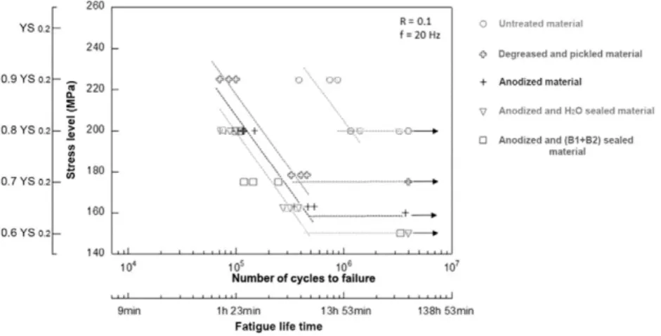
Fatigue life and corrosion fatigue life tests were performed using a 20 Hz sine wave with a stress ratio of R = 0.1 (with R =σmin/σmax).
The results of these tests are presented as a plot of stress level (MPa) as a function of the number of cycles to failure (S-N curves). Several stress levels (from 40 to 90% of YS0.2) were considered, according to
the YS preliminarily determined by performing tensile tests for each surface treatment.
2.6. Scanning electron microscope observations and interferometry measurements
Scanning electron microscopy (SEM-LEO-435-VP) observations were performed with an incident electron beam between 10 kV and 15 kV to carefully examine the corrosion defects and the fracture sur-faces obtained after tensile and fatigue and/or corrosion fatigue tests.
The sample surfaces were also characterized by using an interferometer (Zygo New View 5000) with a white light source.
3. Results and discussion
3.1. Preliminary characterization of the effect of surface treatments on cor-rosion resistance of AA2024-T3
For a better understanding of the effect of surface treatments on cor-rosion fatigue results, the corcor-rosion resistance of the AA2024-T3 after the different steps of the surface treatments (i.e. pre-treatment, anodi-zation and sealing) was evaluated by performing salt-spray tests and electrochemical measurements in a 0.85 M NaCl solution.
3.1.1. Corrosion resistance of AA2024-T3 during salt-spray tests
Fig. 4shows the results of salt-spray tests for anodized samples and sealed samples. For anodized samples without sealing, pits are observed after only 24 h of salt-spray tests while, for sealed samples, thefirst pit was observed after about 200 h of exposure for hydrothermal sealing and about 2000 h for (B1 + B2) sealing. Therefore, results highlighted the beneficial effect of sealing process on the corrosion resistance of the AA2024-T3 compared to the only anodized samples. They also showed that (B1 + B2) sealing induced a better corrosion protection than hydrothermal sealing.
3.1.2. Corrosion behavior of AA2024-T3 during continuous exposure to a 0.85 M NaCl solution
Fig. 5shows the anodic part of the current-potential curves for AA2024-T3 after each step of the surface treatment, i.e. degreasing, pickling, anodization and hydrothermal or (B1 + B2) sealing. For both the degreased and (degreased + pickled) samples, the strong increase of the current after the corrosion potential showed that the samples were susceptible to corrosion in this electrolyte, and in particular to pitting corrosion as shown by OM observations performed after the Fig. 5. Polarization curves of AA2024-T3 in 0.85 M NaCl (pH = 6) for each step of surface treatment.
Table 3
Polarization resistance measured after 5 min and 60 min in a 0.85 M NaCl solution (pH 6) for AA2024-T3 after each step of the surface treatment.
AA2024-T351 Rp (Ω/cm2) (5 min) Rp (Ω/cm2
) (60 min) Degreased and pickled 5.9 4.2 · 10−2
Anodized 3.7 · 102
2.5 Anodized and hydrothermally sealed 2.4 · 104
4.7 · 102
Anodized and (B1 + B2) sealed 1.7 · 103
1.3 · 102
Table 4
Tensile properties of AA2024-T351 untreated and anodized. Surface state Yield strength YS0.2 (MPa) Ultimate tensile stress UTS (MPa) Elongation to failure Ef(%) Untreated 250 ± 7 410 ± 10 9.8 ± 2 Anodized 246 ± 9 408 ± 12 9.5 ± 3
polarization tests. The anodic current densities for the anodized samples were slightly lower than for the degreased and (degreased + pickled) samples showing a better corrosion resistance due to the presence of the anodicfilm on the sample surface. For sealed anodic films, cur-rent-densities were much lower with the presence of a passive plateau after the corrosion potential followed by a strong increase of the current densities corresponding to the formation of thefirst pits. After this breakdown potential, several current jumps were observed which could be related to the formation of new single pits[23]. Comparison of the width of the passive plateau and of the current densities showed that hydrothermal sealing led to a better corrosion resistance compared to (B1 + B2) treatment. These electrochemical measurements were corroborated by OM observations of the sample surfaces after the polar-ization tests which showed a good correlation between the pit density and the anodic current densities. According to polarization curves, the hydrothermal sealed samples presented the lowest pit density.
Rpvalues (Table 3) determined for the AA2024-T3 samples after
each step of the surface treatment were consistent with the results of
potentiodynamic polarization tests. Anodicfilm was 100 times more re-sistive than the material surface only degreased and pickled. Further-more, the hydrothermal sealing seemed to lead to the best corrosion resistance compared to the (B1 + B2) sealing. It is worth noting here that the Rp values measured for degreased and pickled samples were very low suggesting that the pre-treated surfaces should be slightly cor-roded due to the pre-treatment. This hypothesis will be discussed and strengthened later by SEM observations of fatigue fracture surfaces.
It was worth noting also that electrochemical measurements per-formed during continuous immersion in NaCl solution revealed the ben-eficial effect of sealing concerning the corrosion resistance of the AA2024-T3 as observed with salt-spray tests. However, continuous im-mersion tests and salt-spray tests led to contradictory results concerning the efficiency of hydrothermal sealing compared to (B1 + B2) sealing. All these preliminary results tended to show that a correlation between continuous immersion and salt-spray tests was not possible which could be related to the very different exposure con-ditions. Corrosion mechanisms andfinally corrosion kinetics were Fig. 6. Effect of surface treatment on fatigue life of AA2024-T351 in air at 25 °C.
probably different due to differences in oxygenation and drying phe-nomena. Moreover, salt-spray tests results are based on a regular visual inspection of macropits, while electrochemical measurements allow to detect thefirst steps of corrosion non-detectable visually. This point will be discussed later in this paper.
3.2. Effect of the surface treatments on the fatigue resistance of AA2024-T351
The tensile mechanical characteristics of untreated and anodized AA2024 are summarized inTable 4. No significant difference was ob-served, probably due to the low thickness of the anodicfilm, i.e. 5 μm. Therefore, the same mechanical loading was applied during fatigue and corrosion fatigue tests for all samples.
3.2.1. Fatigue endurance behavior of AA2024-T351
Fatigue life curves are presented inFig. 6for non-corroded samples after each step of the surface treatment. Results showed a low scattering of fatigue lives on the basis of three fatigue tests performed at a given stress level. The surprising low scattering in fatigue lives for a given stress level will be explained later in this paper.
For the untreated alloy AA2024-T351, fatigue life decreased logically when the applied stress increased. The endurance limit was observed around 200 MPa, i.e. 80% of YS0.2. Concerning the degreased and pickled
material, a surprising decrease in fatigue life was observed, slightly less than one order of magnitude in comparison with the untreated metal; the result suggested that the pre-treatment, more probably the pickling step, has a strong influence on the material surface. The endurance limit was observed around 175 MPa, i.e. 70% of YS0.2.
The anodization process following the pre-treatment (degreasing and pickling) induced a strong fatigue life decrease compared to the un-treated material, i.e. one order of magnitude from 60% to 90% of YS0.2,
and an additional fatigue life decrease of 10% compared to the degreased and pickled material. The decrease in fatigue life for anodized aluminium alloy is consistent with the literature results[3–6]and, as a reminder, is related either to the brittle character of anodicfilm[11– 14]or to tensile residual stresses[15]thatfinally promote crack initia-tion. However, these results suggested again that mainly pickling was responsible for the fatigue life decrease.
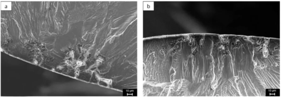
Sealing processes, i.e. hydrothermal and (B1 + B2) treatments, in-duced a very slight additional decrease in fatigue which was probably related to the dispersive character of fatigue crack initiation Fig. 8. SEM observations of fracture surface of degreased and pickled material in air at 25 °C and 80% of YS0.2a) Global view b) Zoom on initiation site.
Fig. 9. Distribution of pickling-induced pit width formed after pickling process for a 2 × 2 mm2
phenomenon. For anodized and (anodized and sealed) material, the en-durance limit was observed around 155 MPa, i.e. 60% of YS0.2.
3.2.2. SEM observations of fatigue fracture surfaces of AA2024-T351 in air 3.2.2.1. Untreated AA2024-T351. The SEM fracture surfaces of untreated material are presented inFig. 7. Independently of the stress level, the fracture surfaces presented three distinct zones characterized by differ-ent rupture modes: the zone of crack initiation, the zone of crack prop-agation and the zone corresponding to thefinal rupture. Crack initiation was always localized on coarse intermetallic particles (Fig. 7a) because it was due to the localisation of plasticity on coarse particles, leading to their shearing. A crystallographic propagation, i.e. cleavage fracture, characterized by river patterns, was observed on the fracture surfaces (Fig. 7b) associated with striations. This type of crystallographic propa-gation is controlled by environment. Petit and co-workers[24], as well as other authors[25–27]have analysed environmentally-assisted fa-tigue crack propagation according to two distinct and sequential mechanisms:
- a crack growth enhancement induced by adsorption of water vapour molecules and subsequent reduction of the surface energy; - a crack-tip embrittlement linked to a reduction of the cleavage
strength by hydrogen atoms released by the dissociation of previ-ously adsorbed water vapour molecules and then introduced into the material cyclically deformed at the crack tip.
Finally, with the increase in the crack propagation rate, crystallo-graphic propagation disappeared in favour of thefinal ductile rupture zone characterized by dimples (Fig. 7d).
3.2.2.2. Degreased and pickled AA2024-T351. The SEM fracture surfaces of degreased and pickled material are presented inFig. 8. These observa-tions focused on the initiation zone, given that propagation andfinal rupture mechanisms were strictly similar to the rupture observed for untreated material.
As suggested by the low Rpvalues (Table 3) and fatigue endurance
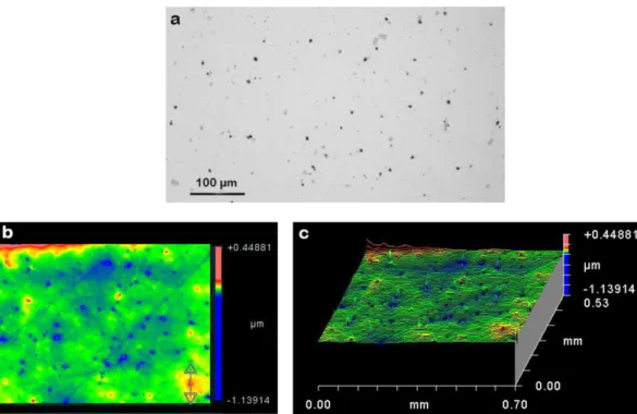
curves, localized corrosion, i.e. pitting corrosion, containing some corro-sion products (Fig. 8b) was observed on fracture surface. These pits Fig. 10. a) OM observation on AA2024-T351 surface after degreasing and pickling, b) 2D-interferometry map, c) 3D-interferometry map.
were responsible for a premature crack initiation which was only local-ized on a single pit since no multi-site cracking was observed. On the basis of SEM micrographs, the pit width was approximatively 10μm for a depth of 150μm. These corrosion defects formed during the pickling process and were identified as a major cause for accelerated crack nucle-ation during subsequent fatigue loading in other works[17,28,29]. To confirm the effect of pickling on pit formation, OM observations were per-formed in order to determine the distribution of pickling-induced pits (Fig. 9) in combination with interferometry measurements to analyze their length (Fig. 10). For interferometry map, results obtained for only one degreased and pickled sample are given as an example. As expected, some pits were formed after pickling, resulting from galvanic coupling be-tween intermetallic particles and matrix. However, it was not possible to confirm the pit depth by using interferometry because of the presence of corrosion products inside the pits. Concerning the distribution of pit width, the result confirmed the SEM observations which had shown that crack initiation occurred preferentially on wider pits (around 10μm).
It was surprising to see that the industrial pickling process induced pitting corrosion. The industrial sulfo-nitric pickling was especially de-veloped to avoid this type of phenomenon. It could be possible that in-termetallic particle reactivity was exacerbated after machining and mirror polishing of samples that could be confirmed by Atomic Force Microscopy and Kelvin probe Force Microscopy as studied by Lacroix and coworkers[30]. Finally this premature crack initiation on pitting corrosion defects induced by pickling process can explain the low scat-tering of fatigue lives observed in this work.
3.2.2.3. Anodized AA2024-T351. SEM observations of fracture surfaces for anodized material are presented inFig. 11. Once again, the observations were focused on initiation stage, propagation andfinal rupture modes remaining unchanged. SEM observations confirmed the presence of pits under the anodicfilm. However, a multi-site crack initiation was
observed that probably explained the additional decrease in fatigue life of 10% compared to only degreased and pickled material; further-more, the pit size where crack initiation occurred was abnormally im-portant. The results could be related to the works of Savas and coworkers on AA7075 who studied the effect of different anodization pretreatments on localized corrosion behavior[31]. They suggested that, if the pits initiating during the pretreatment exposures, i.e. pickling in this work, were beyond a threshold size, about 10–20 μm, a higher current density could be measured at these locations during pickling and anodization processes, thus resulting in larger and deeper pit struc-tures. These surface defects enhanced fatigue crack nucleation. For smaller pits, of about 1–5 μm, the anodic process had a smoothing effect and the anodicfilm growth tended to passivate the pits. These explana-tions could explain the multi-site crack initiation observed and the pit size.
3.2.2.4. Anodized and sealed AA2024-T351. SEM observation of fracture surfaces of anodized and sealed material are presented inFig. 12for the two sealing processes.
As observed for anodized samples, crack initiation occurred on wide pits under the anodicfilm and a multi-site crack initiation was observed. As a reminder, the two sealing processes led to the same fatigue life de-crease than the anodized material.
3.3. Effect of pre-corrosion and surface treatment on the fatigue life proper-ties of AA2024-T351
To better understand the corrosion fatigue interactions,first, the ef-fect of pre-corrosion damage on fatigue life and fracture modes were characterized. Two pre-corrosion treatments were considered, i.e. a 240 h salt-spray exposure and a continuous immersion in 0.85 M NaCl during 120 h.
Fig. 12. SEM observations of fracture surface of anodized and sealed material in air at 25 °C and 80% of YS0.2a) Hydrothermal sealing b) (B1 + B2) sealing.
3.3.1. Effect of salt-spray pre-exposure on fatigue life of AA2024-T351 The fatigue life curves plotted after a 240 h pre-corrosion treatment by salt-spray exposure for anodized and sealed samples are presented inFig. 13.
Results of endurance tests showed that hydrothermally sealed sam-ples presented a strong fatigue life decrease after an exposure of 240 h in salt-spray contrary to (B1 + B2) sealed samples which presented a behavior close to the fatigue behavior of non-precorroded anodized and sealed samples. According to salt-spray tests results (Fig. 4), (B1 + B2) sealing led to a better corrosion resistance than hydrother-mal sealing for these exposure conditions which suggested that the fa-tigue behavior of pre-corroded samples could be related to the corrosion protection efficiency of the sealing. The slight fatigue-life de-crease observed for the pre-corroded (B1 + B2) sealed samples com-pared to non-corroded (B1 + B2) sealed samples could also suggest that some pits were present after salt-spray exposure whose size was too small to be visually observed but sufficiently wide to be an initiation site for fatigue crack.
SEM observations of fatigue fracture surfaces of salt-spray pre-ex-posed samples are presented inFig. 14. They were focused on initiation sites given that propagation andfinal rupture modes are unchanged compared to fatigue tests without pre-corrosion treatment.
In agreement with the salt-spray and endurance tests which had dem-onstrated the very good corrosion resistance of (B1 + B2) sealing in these exposure conditions, it was observed that crack initiation occurred on pits localized on sealed anodicfilm for hydrothermal sealing (Fig. 14a) contrary to crack initiation for (B1 + B2) sealed samples (Fig. 14b) localized prefer-entially on pits issued from the pickling treatment. The results showed that pits formed during salt-spray exposure enhanced the fatigue life decrease in parallel of pits issued from the pickling process.
3.3.2. Effect of a continuous pre-immersion in NaCl solution on fatigue life of AA2024-T351
The fatigue life curves plotted after a 120 h pre-corrosion treatment by continuous immersion in a 0.85 M NaCl solution are presented inFig. 15. Anodized samples presented a fatigue life decrease more pro-nounced than anodized and sealed samples in relation with a lower cor-rosion resistance as shown by electrochemical measurements. Moreover, in agreement with electrochemical measurements, hydro-thermal sealing process presented a better fatigue behavior than (B1 + B2) sealing in terms of fatigue life after continuous immersion, particularly for high stress level. This result showed that the fatigue be-havior of the samples was at least partially controlled by their corrosion resistance related to pit formation on the sealed anodicfilm during pre-corrosion treatment; it enhanced the role of stress level on fatigue crack initiation from small pits formed on anodicfilm surface during pre-cor-rosion treatment and the notion of defect critical size.
Finally these results were consistent with the electrochemical mea-surements and confirmed the difficulty, if not the impossibility, to com-pare salt-spray and continuous immersion tests.
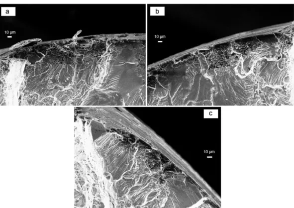
SEM observations of fatigue fracture surfaces of AA2024-T351 pre-corroded by continuous immersion.
SEM observations of fatigue fracture surfaces of samples pre-corrod-ed by continuous immersion are presentpre-corrod-ed inFig. 16. They were focused on initiation sites. These micrographs showed that the majority of fa-tigue crack initiation sites were localized on pits formed during the pick-ling step. However, previous results showed also that the fatigue life decrease observed on S-N curves after pre-corrosion was due to pits lo-calized on anodicfilm, including (B1 + B2) sealing (Fig. 16c). This result confirmed that (B1 + B2) sealing was optimized on the basis of salt-spray results and not for continuous immersion exposure.
Fig. 14. SEM observations of fracture surface of salt-spray pre-exposed material at 80% of YS0.2a) Hydrothermal sealing b) (B1 + B2) sealing.
3.4. Corrosion fatigue behavior of AA2024-T351
The results of fatigue life tests performed in corrosive media, i.e. a 0.85 M NaCl solution, at 35 °C are presented inFig. 17for anodized and sealed samples. Results obtained in air are reported for comparison.
Table 5summarized all the fatigue results for more clarity and especially the time spent in the NaCl solution for each test. The results showed that corrosion fatigue induced an additional decrease in fatigue life for both sealing treatments in comparison with fatigue life in air and, for high stress levels, fatigue life after continuous immersion. These results sug-gested that interaction between cyclic loading and corrosive media was very strong on the basis of the time spent in media which was very short for corrosion fatigue conditions compared to the 120 h of continuous immersion; this interaction has to be taken into account to explain the fatigue life decrease observed.
A possible interpretation could be based on the fact that, under cor-rosion fatigue conditions, crack initiation were expected to occur from both pits issued from pickling process and interaction between cyclic loading and corrosive media. For low stress levels, initiation occurred essentially on pits issued from pickling and not from corrosion fatigue
interaction on the basis of the relative similarity observed in corrosion fatigue life between anodized, hydrothermally sealed and (B1 + B2) sealed samples and those pre-corroded by a continuous immersion in a NaCl solution. However, at high stress levels, this interaction was suf-ficiently exacerbated to induce a strong decrease in fatigue life of hydro-thermal sealing despite the fact that this sealing presented the best corrosion resistance for continuous immersion conditions. It was as-sumed that this sealing promoted a more significant mechanical em-brittlement of the anodicfilm for high stress levels than (B1 + B2) sealing and therefore, enhanced crack initiation on new corrosion pits issued from the anodicfilm damage.
The SEM observations of fatigue fracture surfaces of samples pre-corroded by continuous immersion are presented inFig. 18. Particular attention was paid to initiation sites and anodicfilms (Fig. 19).
As seen on global view of fracture surfaces, a multi-site crack initia-tion was observed for both anodized and (B1 + B2) sealed samples; it was much more important for hydrothermal sealing. This was consis-tent with previous results and comments related to a mechanical em-brittlement of the hydrothermally sealed anodicfilm by mechanical cyclic loading followed by pitting corrosion. A zoom on anodicfilms Fig. 16. SEM observations of fatigue crack initiation at 80% of YS0.2of AA2024-T351 pre-corroded by continuous immersion. a) anodized, b) hydrothermally sealed c) (B1 + B2) sealed.
Table 5
Average number of cycles to failure and time spent in media vs. stress level for anodized and sealed samples and test conditions.
Experimental conditions Stress level Anodized Anodized + H2O sealing Anodized + (B1 + B2) sealing
Fatigue in air σ = 80% of YS0.2 1.1 · 105 0 min 8 · 104 0 min 1 · 105 0 min σ = 65% of YS0.2 5 · 05 0 min 3 · 105 0 min 4.8 · 105 0 min 120 h continuous immersion in a 0.85 M NaCl solution + fatigue in air σ = 80% of YS0.2 1.2 · 104
7200 min 3.7 · 104 7200 min 2.3 · 104 7200 min σ = 65% of YS0.2 4.2 · 104 7200 min 8.3 · 104 7200 min 7.6 · 104 7200 min Corrosion fatigue in a 0.85 NaCl solution σ = 80% of YS0.2 2.6 · 104
22 min 8.7 · 103 7 min 2.5 · 104 21 min σ = 65% of YS0.2 6.8 · 104 57 min 7.8 · 104 65 min 6 · 104 50 min
confirmed these results with a very strongly damaged anodic film in the case of hydrothermal sealing in comparison with the (B1 + B2) sealing. This strong damage was also observed after fatigue tests in air and fa-tigue tests after continuous immersion. Finally, this damage of the hy-drothermally sealed anodicfilm enhanced probably the fast apparition of pits, sufficiently wide to induce crack initiation. This fast crack initia-tion during thefirst minutes of immersion under corrosion fatigue was already seen in previous works [32,33]. Moreover, Shahzad and
coworkers have revealed for AA 2214 T6 the presence of cavity like de-fects and crazing in the sealed (in nickel-acetate solution at 98 °C for 20 min) anodicfilm, promoting fatigue crack initiation[17].
To explain the differences in mechanical behavior between hydro-thermally sealed and (B1 + B2) sealed anodicfilms, further SEM-FEG observations were performed (Fig. 20). They showed that hydrothermal process led to a superficial sealing of the anodic film[34]. Sealing con-cerned only 1μm compared to the 5 μm global thickness of the anodic Fig. 17. Effect of surface treatment on corrosion fatigue life of AA2024-T351 in 0.85 M NaCl solution at 35 °C.
Fig. 18. SEM observations of fracture surfaces after corrosion fatigue tests in 0.85 M NaCl at 80% of YS0.2of a) anodized material, b) hydrothermally sealed material and c) (B1 + B2) sealed
film. Concerning the (B1 + B2) sealing, the sealed layer was particularly thin (100–150 nm) and compact and covered uniformly the anodic film, without creating porosity. These differences in sealed layer morphology could explain the difference in mechanical resistance between the sealed anodicfilms. Some additional tests need to be conducted to val-idate or not this hypothesis such as in-situ electrochemical analyses and local observations. This will be done in future works.
4. Conclusions
The effect of several surface treatments, i.e. anodization and sealing with two sealing processes (hydrothermal and (B1 + B2)), on fatigue behavior of AA2024-T351 was studied in air for as prepared and pre-corroded samples. The results were compared to those obtained during corrosion fatigue tests in a 0.85 M NaCl solution.
Pre-corrosion conditions corresponded to continuous immersion in NaCl solution or salt-spray tests. Results showed that it was difficult to rig-orously compare results of salt-spray tests and continuous immersion ex-posure. For salt-spray tests, the best corrosion resistance was related to the (B1 + B2) sealing, while for continuous immersions, the hydrother-mal sealing led to a better corrosion resistance of 2024 samples.
Fatigue life tests in air showed that fatigue crack initiation was local-ized on pits formed during degreasing and pickling steps, inducing a no-ticeable fatigue life decrease for all surface treatments. This result was
already observed in other works as previously said in the introduction
[17–19].
Fatigue life tests in air on pre-corroded samples by continuous im-mersion revealed that anodized samples presented a fatigue life de-crease more pronounced than anodized and sealed samples in relation with a lower corrosion resistance as shown by electrochemical methods. Moreover, according to electrochemical characterization, the fatigue behavior of hydrothermally sealed samples was better than that of (B1 + B2) sealed samples after continuous immersion.
Fatigue life tests in air on pre-corroded samples by salt-spray expo-sure showed that hydrothermally sealed samples showed a strong fa-tigue life decrease after a 240 h salt-spray exposure contrary to (B1 + B2) sealed samples which presented a similar fatigue behavior than for non-precorroded anodized and sealed samples. However, a slight fatigue-life decrease was observed for pre-corroded (B1 + B2) sealed material compared to as-prepared (B1 + B2) sealed material suggesting that salt-spray exposure led to the formation of pits that were too small to be visually observed but sufficiently wide to be an ini-tiation site for fatigue crack.
Concerning the corrosion fatigue tests, the results indicated that cor-rosion fatigue induced a decrease in fatigue life for both sealing treat-ments in comparison with fatigue life in air and, for high stress level, fatigue life after continuous immersion. Crack initiation occurred pref-erentially on pits formed during the degreasing and pickling steps but also on pits issued from interaction between cyclic loading and Fig. 19. SEM observations of anodicfilms after corrosion fatigue tests in 0.85 M NaCl at 80% of YS0.2of a) hydrothermally sealed material and b) (B1 + B2) sealed material.
corrosive media. Results showed that hydrothermally sealed anodic films were very strongly damaged by fatigue loading in comparison with the (B1 + B2) sealing. The differences in sealed layer morphology could explain the difference in mechanical resistance of the both sealed anodicfilms.
Acknowledgments
Kévin Giffard thanks MECAPROTEC Industries and the National Asso-ciation of Research and Technology (ANRT) for his PhD grant (CIFRE n° 2011/1617). This work was part of the APACA III project,financially sup-ported by the European Regional Development Fund (ERDF), the French Ministry of Industry (DIRECCTE) and the Midi-Pyrénées Region. The au-thors thank Benoit Fori and MECAPROTEC Industries, for performing the salt-spray tests.
References
[1] X. Zhao, G.S. Frankel, B. Zoofan, S. Rokhlin, In situ X-ray radiographic study of inter-granular corrosion in aluminum alloys, Corros. Sci. 59 (2003) 1012–1018.
[2] M. Posada, L.E. Murr, C.S. Niou, D. Roberson, D. Little, R. Arrowood, D. George, Exfo-liation and related microstructures in 2024 aluminum body skins on aging aircraft, Mater. Charact. 38 (1997) 259–272.
[3] M.R. Bayoumi, The mechanics and mechanisms of fracture in stress corrosion crack-ing of aluminium alloys, Eng. Fract. Mech. 54 (1996) 879–889.
[4] X. Liu, G.S. Frankel, B. Zoofan, S. Rokhlin, In-situ observation of intergranular stress corrosion cracking in AA2024-T3 under constant load condition, Corros. Sci. 49 (2007) 139–148.
[5] W. Zhang, G.S. Frankel, Anisotropy of localized corrosion in AA2024-T3, Electrochem. Solid-State Lett. 3 (2000) 268–270.
[6] C. Augustin, E. Andrieu, C. Blanc, J. Delfosse, G. Odemer, Empirical propagations laws of intergranular corrosion effects affecting 2024 T351 alloy in chloride solutions, J. Electrochem. Soc. 157 (2010) 428–436.
[7] C. Larignon, J. Alexis, E. Andrieu, G. Odemer, C. Blanc, Propagation of intergranular corrosion defects in AA2024-T351 evaluated by a decrease in mechanical resistance, J. Electrochem. Soc. 161 (2014) 1–10.
[8] A.S.M. Handbook, Corrosion, nineth ed.Vol. 13, ASM International, USA, 1998.
[9] S. Wernick, R. Pinner, P. Sheasby, Surface Treatment and Finishing of Aluminium and its Alloys, sixth ed. Finishing Publications Ltd., England, 2001.
[10]L. Hao, B.R. Cheng, Sealing processes of anodic coatings - past, present and future, Met. Finish. 12 (2000) 8–18.
[11] B. Lonyuk, I. Apachitei, J. Duszczyk, The effect of oxide coatings on fatigue properties of 7475-T6 aluminium alloy, Surf. Coat. Technol. 201 (2007) 8688–8694.
[12] R. Sadeler, Effect of a commercial hard anodizing on the property of a 2024-T6 alu-minium alloy, J. Mater. Sci. 41 (2006) 5803–5809.
[13] R.G. Rateick, T.C. Binkowski, B.C. Boray, Effect of hard anodized thickness on the fa-tigue of AA6061 and C355 aluminium, J. Mater. Sci. Lett. 15 (1996) 1321–1323.
[14] E. Cirik, K. Genel, Effect of anodic oxidation on fatigue performance of 7075-T6 alloy, Surf. Coat. Technol. 202 (2008) 5190–5201.
[15]J.A.M. Camargo, H.J.C. Voorwald, M.O.H. Cioffi, M.Y.P. Costa, Coating residual stress effects on fatigue performance of 7050-T7451 aluminum alloy, Surf. Coat. Technol. 201 (2007) 9448–9455.
[16] A.M. Cree, G.W. Weidmann, Effect of anodized coatings on fatigue cracks rates of al-uminium alloy, Surf. Eng. 13 (1997) 51–55.
[17] M. Shahzad, M. Chaussumier, R. Chieragatti, C. Mabru, F. Rezai-Aria, Effect of sealed anodicfilm on fatigue performance of 2214-T6 aluminum alloy, Surf. Coat. Technol. 206 (2012) 2733–2739.
[18] G.E. Thompson, L.C. Zhang, J.E. Smith, P. Skeldon, Boric/sulfuric acid anodizing of alu-minum alloys 2024 and 7075:film growth and corrosion resistance, Corros. Sci. 55 (1999) 1052–1060.
[19] J.H. Liu, M. Li, S.M. Li, M. Huang, Effect of the microstructure of Al 7050-T7451 on an-odic oxide formation in sulfuric acid, Int. J. Miner. Metall. Mater. 16 (2009) 432–438.
[20] G.C. Tu, R.Y. Hwang, I.T. Chen, A study of corrosion fatigue behavior of anodized and unanodized 2024-T3 aluminium alloy, J. Mater. Sci. 26 (1991) 1375–1382.
[21]G.C. Tu, I.T. Chen, R.Y. Hwang, The effect of anodizing on the corrosion fatigue be-havior of 2024-T3 aluminium alloy, Int. J. Fatigue 33 (1991) 527–534.
[22] V. Guillaumin, G. Mankowski, Localized corrosion of 2024T351 aluminium alloy in chloride media, Corros. Sci. 41 (1998) 421–438.
[23] Y. Zuo, P.H. Zhao, J.M. Zhao, The influence of sealing methods on corrosion behavior of anodized aluminum alloys in NaCl solutions, Surf. Coat. Technol. 166 (2003) 237–242.
[24]J. Petit, G. Henaff, C. Sarrazin-Baudoux, in: J. Petit, P. Scott, I. Milne, R.O. Ritchie, B. Karihalooeditors (Eds.),Environmentally-Assisted Fatigue in the Gaseous Atmo-sphere, in: Environmentally-Assisted Fracture, Comprehensive Structural Integrity, vol 6, 2003, pp. 211–280 Amsterdam.
[25]G. Henaff, G. Odemer, A. Tonneau-Morel, Environmentally-assisted fatigue crack growth mechanisms in advanced materials for aerospace applications, Int. J. Fatigue 29 (2007) 1927–1940.
[26]C.T. Liu, E.H. Lee, C.G. McKamey, An environmental effect as the major cause for room-temperature embrittlement in FeAl, Scr. Metall. Mater. 23 (1989) 875–880.
[27] W. Elber, The Significance of Crack Closure, in: Damage Tolerance in Aircraft Struc-tures, ASTM STP 486, PA: American Society for Testing and Materials, Toronto, On-tario, Canada, Philadelphia, 1971 230–242.
[28]A. Monsalve, M. Paez, M. Toledano, A. Artigas, N. Valencia, S-N-P curves in 7075-T7351 and 2024-T3 aluminium alloys subjected to surface treatments, Fatigue Fract. Eng. Mater. Struct. 30 (2006) 748–758.
[29]S.A. Barter, P.K. Sharp, G. Clark, Initiation and early growth of fatigue cracks in an aerospace aluminium alloy, Fatigue Fract. Eng. Mater. Struct. 25 (2002) 111–125.
[30] L. Lacroix, Mécanismes de Corrosion localisée de l'alliage d'aluminium 2024, Apport de La Microscopie à Force Atomique (AFM) couplée Au Mode Kelvin (KFM) et Des Alliages modèles, Université de Toulouse, 2008 Thesis of the.
[31] T.P. Savas, J.C. Earthman, Surface characterization of 7075-T73 aluminium exposed to anodizing pretreatment solutions, J. Mater. Eng. Perform. 17 (2008) 674–681.
[32]A. Laurino, E. Andrieu, J.-P. Harouard, G. Odemer, J.-C. Salabura, C. Blanc, Effect of corrosion on the fatigue life and fracture mechanisms of 6101 aluminum alloy wires for car manufacturing applications, Mater. Des. 53 (2014) 236–249.
[33] M. Guerin, J. Alexis, E. Andrieu, C. Blanc, G. Odemer, Corrosion-fatigue lifetime of al-uminium-copper-lithium alloy 2050 in chloride solution, Mater. Des. 87 (2015) 681–692.
[34]K. Giffard, Study of the Sealing Mechanisms of the Anodic Films on Aeronautical 2024 Aluminium Alloy, Thesis of the Université de Toulouse, 2015.