Distance Dependence of Single-Molecule Energy Transfer to
Graphene Measured with DNA Origami Nanopositioners
I. Kaminska,
*
,†J. Bohlen,
‡S. Rocchetti,
‡F. Selbach,
‡G. P. Acuna,
§and P. Tinnefeld
*
,‡†Institute of Physical Chemistry of the Polish Academy of Sciences, 01-224 Warsaw, Poland
‡Department of Chemistry and Center for NanoScience, Ludwig-Maximilians-Universität München, 80539 München, Germany §Department of Physics, Université de Fribourg, Ch. du Musée 3, CH-1700 Fribourg, Switzerland
*
S Supporting InformationABSTRACT: Despite the thorough investigation of graphene since 2004, altering its surface chemistry and reproducible functionalization remain challenging. This hinders fabrication of more complex hybrid materials with controlled architec-tures, and as a consequence the development of sensitive and reliable sensors and biological assays. In this contribution, we introduce DNA origami structures as nanopositioners for placing single dye molecules at controlled distances from graphene. The measurements of fluorescence intensity and lifetime of single emitters carried out for distances ranging from 3 to 58 nm confirmed the d−4 dependence of the excitation energy transfer to graphene. Moreover, we determined the characteristic distance for 50% efficiency of
the energy transfer from single dyes to graphene to be 17.7 nm. Using pyrene molecules as a glue to immobilize DNA origami nanostructures of various shape on graphene opens new possibilities to develop graphene-based biophysics and biosensing.
KEYWORDS: DNA origami, graphene, single molecules,fluorescence quenching, energy transfer
G
raphene is a two-dimensional carbon lattice resembling a honeycomb, which has attracted great attention since 2004, when it was experimentally isolated for the first time. Due to its unique electronic, optical, and mechanical properties, it has been intensively explored worldwide and found applications probably in every branch of science.1 Its gapless energy band structure and linear dispersion relation near the corners of the Brillouin zone result in a frequency-independent light absorption, governed solely by the fine-structure constant,α ≈ 1/137. As a result, this only one-atom thick material absorbs as much asπα ≈ 2.3% of light, over the visible and near-infrared spectral regions.2 As a consequence, graphene behaves as an extraordinary energy sink and a unique acceptor system, which is one of the key characteristics of graphene and graphene-related two-dimensional materials exploited in the field of optical biosensors and distance rulers.3,4 Fluorescent dyes placed close to graphene are strongly quenched and their displacement from graphene can restore fluorescence.5−8 It has been demonstrated both theoretically and experimentally that the energy transfer from a molecule (a single dipole) to graphene (“2D array of dipoles”) strongly depends on the distance d between both and scales proportional to d−4.8−11Whereas the distance depend-ence is well understood, reports vary with respect to the d0value, which states the distance of 50% quenching efficiency. This variation is related to the different emitters used (e.g., quantum dots, nitrogen-vacancy centers, or dyes embedded in
crystals) and how the distance to the graphene layer was controlled, with reported values range from d0 = 8 to 20
nm.5−7,11,12 In one work quenching up to 60 nm was reported.12
Hitherto, gold surfaces and not graphene surfaces are commonly used influorescence quenching biosensing because, besides the quenching, a well-developed surface chemistry exists. Gold has thus been the material of choice for biosensing13−15 as well as for MIET16,17 (metal induced energy transfer) super-resolution imaging. Compared to gold, graphene offers the outstanding advantage of good optical transparency in the far-field and less background fluorescence. So far, however, graphene and other related 2D materials lack the chemical flexibility to carry out complex biomolecular assays. Main problems include missing control over surface chemistry, construct composition and fabrication, and low reproducibility of graphene-based hybrid structures.
In this work, we used DNA origami18as nanopositioners to generally overcome the problem of chemical functionalization of graphene for optical biosensing assays. The DNA origami technique enables the formation of custom-designed DNA nanostructures with a volume of ∼21.000 nm3, and the rich
http://doc.rero.ch
Published in "Nano Letters 19(7): 4257–4262, 2019"
which should be cited to refer to this work.
DNA chemistry available allows placing of arbitrary objects and complex biomolecular assays19−21 at programmed positions on the DNA nanostructure.18,22−24For biomolecular assays, DNA origami can act as a biocompatible surface.25In previous works, DNA origami structures were coupled to pristine graphene either to increase their stability26 or as a template for metallized DNA nanolithography.27However, it was demonstrated with TEM imaging that DNA origami nanoplates were denatured due to hydrophobic interactions of the DNA bases with graphene upon adsorption.28,29 As a universal glue to connect the DNA origami constructs to the graphene layer, we used several pyrene-modified DNA strands that are hybridized to the DNA origami on the one hand and interact with the graphene lattice viaπ−π stacking interactions on the other hand. We show that this immobilization scheme provides stable DNA origami structures for different geo-metries and enables placing of single, freely rotatingfluorescent molecules at defined distances to the graphene layer. We exploit the exquisite distance control of singlefluorescent dyes to graphene in order to revisit the distance dependence of energy transfer to graphene. Our narrow intensity −fluores-cence lifetime distributions confirm the d−4law with a precise value of d0of 17.7 nm in aqueous buffer solution and present
the basis for a broad range of applications in biosensing and optoelectronics.
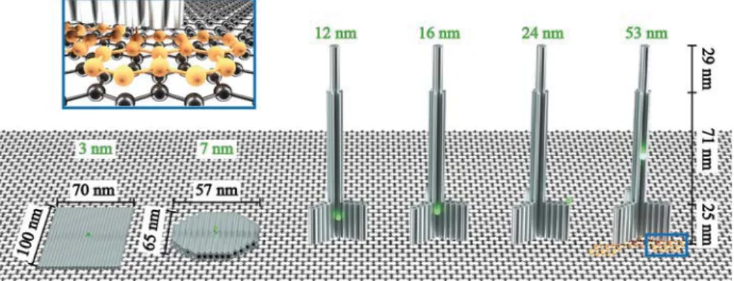
Results and Discussion. The selection of DNA origami shapes was guided by the possibility to position a single dye molecule at a designed height from the bottom (distance from graphene) and included rectangular- (nanorectangle = NR), disc- (nanodisc = ND), and pillar-shaped (nanopillar = NP) self-assembled DNA origami structures (see Figure 1). Each DNA origami structure contains one dye molecule (ATTO542) marked as a small green sphere, which is positioned at the height of 3 nm (NR), 7 nm (ND), 12 nm
(NP1), 16 nm (NP2), 24 nm (NP3), and 53 nm (NP4) (further details are included in the Materials and Methods). The selected values cover the range of distances for which the energy transfer from a single dye molecule to graphene is expected to vary from 0 to almost 100%.8 As the dyes are attached to the DNA origami by six-carbon linkers and measurements were carried out in buffer solution, it is expected that thefluorescent dyes are free to rotate on the flexible linker. Additionally, at the bottom of each structure, we incorporated six to eight staple strands with single-stranded extensions protruding from the DNA origamis. The protrusions are used to label the DNA origami with pyrene-modified complementary oligonucleotides. The pyrene enabled selective binding of the DNA origami with the bottom side to the graphene layer (Figure 1 blue frame). External labeling with extended staple strands allowed modular modifications also for other moieties. For example, in order to measure the same samples on glass, biotin-modified oligonucleotides were used and DNA origami structures were immobilized on neutravidin−biotinylated BSA surfaces.30 A detailed descrip-tion of the DNA origami structures and sample preparadescrip-tion can be found in theMaterials and Methods, whereas AFM and TEM images of the obtained DNA origami structures are included in the Supporting Information (Figure S1).
Single-moleculefluorescence measurements were carried out with a home-built confocal microscope (further details are included in Imaging and Analysis).Figure 2depicts ATTO542 fluorescence intensity images for each of the six DNA origami structures using 532 nm excitation. The closer the emitter is to the graphene layer, the more its fluorescence is quenched. Therefore, we adjusted the excitation power to always work with a count rate in a regime that showed linear excitation intensity dependent emission. Laser powers ranged from 1μW for three nanopillar samples (NP2, NP3, and NP4), 2μW for
Figure 1. Sketches of rectangular-, disc-, and pillar-shaped DNA origami structures. A single ATTO542 fluorophore (green sphere) is positioned at a height of 3 nm (NR), 7 nm (ND), 12 nm (NP1), 16 nm (NP2), 24 nm (NP3), and 53 nm (NP4). Blue frame: zoom-in of pyrene-modified (orange) DNA strand protruding from DNA origami and interacting with graphene viaπ−π interactions. Gray bars represent double-stranded DNA.
Figure 2. Fluorescence intensity images (5 × 5 μm) obtained for DNA origami structures with a single dye (ATTO542) immobilized on graphene, for 532 nm excitation wavelength, and laser power ranging from 1 to 5μW (NR, 5 μW; ND and NP1, 2 μW; NP2, NP3, and NP4, 1 μW).
one nanopillar sample and the nanodisc (NP1 and ND), to 5 μW for the nanorectangle (NR) DNA origami structure. On all images, we observed that thefluorescence intensities of most spots corresponding to dye molecules are very homogeneous with occasional very bright spots.
We also performed control measurements to confirm that the immobilization of the samples on graphene depends on the number of pyrene molecules. The results of the experiments carried out for NP2 DNA origami structure without pyrene molecules, as well as with one or eight pyrene molecules confirm that only in the last case, the samples are successfully immobilized on graphene (Figure S2). Moreover, we compared immobilization of pyrene-modified DNA origami structures on graphene with the immobilization of DNA origami structures with protruding strands on graphene functionalized with complementary pyrene-modified strands. This experiment clearly shows that the reversed immobilization scheme is not efficient, and it is necessary to incorporate pyrene molecules within DNA origami structures beforehand (Figure S3).
In order to characterize interactions between dye molecules and graphene,fluorescence transients were recorded for each spot. This enabled the identification of single DNA origami structures by observing blinking events (fluctuating between “on”/bright and “off”/dark states) and single-step photo-bleaching (examples offluorescence transients are depicted in
Figure S4). We identified two types of deviations from the
typical single-molecule behavior, which is related to the mentioned brighter spots in the images. In cases with multistep photobleaching, we attributed the signal to aggregates of multiple DNA origami structures, also present in analogous measurements carried out on glass coverslips (Figure S5). In other cases, the brighter spots exhibited single-step photo-bleaching and showed similar intensities and fluorescence lifetimes as molecules of the reference structures measured on glass coverslips. We hence attribute these molecules to DNA origami structures immobilized within small defects/cracks of the graphene layer. Nevertheless, taking into account the small number of such spots (<10%), together with the quality control performed by Graphenea and our additional character-ization using Raman spectroscopy (several tens of spectra obtained from Raman measurements, an exemplary spectrum presented in Figure S6), we conclude that graphene samples used in our measurements have little defects and contami-nations.
For further analysis, only transients with single bleaching steps were considered and used to determine thefluorescence intensity andfluorescence lifetime of each spot (see Imaging
and Analysis for details). As expected, dye molecules
incorporated in DNA origami structures bound to graphene exhibit shorter fluorescence lifetimes compared to samples immobilized on glass (see Figure 3a). Only for the largest distance of 53 nm to graphene (NP4), the fluorescence properties are not affected (see Figure S7) and the unperturbedfluorescence lifetime of 3.25 ns for ATTO542 is obtained.
The reduction of fluorescence intensity and fluorescence lifetime is correlated and arises from the strong near-field interactions between the emitter and graphene.5,8,31Figure 3b shows the relativefluorescence intensity
⟨ ⟩ I I
G
ref as a function of
thefluorescence lifetime, where IGisfluorescence intensity of a
dye molecule within the DNA origami bound to graphene, and ⟨Iref⟩ is the average fluorescence intensity obtained for the
reference sample, NP4. Due to the differences in the applied laser powers in our measurements, all the obtained values of fluorescence intensities were normalized to the laser power of 1 μW. It is noteworthy that narrow and clearly separated populations offluorescence intensity and fluorescence lifetime are obtained, indicating the selectivity and robustness of the immobilization strategy. The homogeneity of the data is also fostered by the binding strategy of the dye, which can rotate during the measurement. It is therefore justified to assume that the measured data reflect the interaction of an averaged dipole orientation with the graphene layer. Interestingly, the position-ing with the pyrene subunits as selective glue even yields narrow distributions for the nanopillar samples NP1 to NP4, which is remarkable in view of the high aspect ratio of this DNA origami. As measurements were carried out for up to 2 days after sample preparation DNA origamis on graphene are also stable and no degradation was observed.
For a quantitative analysis of the interaction between single dye molecules and graphene and its strong distance depend-ence, we investigated how the quenching (relative intensity) and the energy transfer efficiency to graphene both depend on the emitter−graphene distance. The energy transfer efficiency η was calculated from fluorescence lifetimes
η = − ⟨ ⟩ττ
(
L 1 G)
ref , 5−7
where τG is the fluorescence lifetime of
a dye molecule within DNA origami bound to graphene, and
Figure 3. (a) Normalized fluorescence intensity decays of ATTO542 at difference distances to graphene (averaged from 20 decays for each sample). (b) Relativefluorescence intensity as a function of fluorescence lifetime (fluorescence lifetimes were obtained by reconvolution). For better separation of the populations a semilogarithmic presentation is provided.
⟨τref⟩ is the average fluorescence lifetime obtained for the
reference sample, as well as from fluorescence intensities
η = − ⟨ ⟩
(
1 I)
I
I refG .Figure 4show the distance dependent energy
transfer efficiency calculated by both methods. While the shapes of the graphs are similar, lower energy transfer efficiencies were obtained from the fluorescence lifetime graph for the shortest distances (Figure 4a), which we attribute to uncertainty induced by the limited time resolution of the setup (see decays and instrument response function (IRF) in Figure 3a). The energy transfer efficiency obtained from intensities reaches up to 97% quenching for the smallest distance. Wefitted the experimental data (Figure 4b) with the expected d−4 dependence (red line) and obtained a d0 value
(the distance of 50% energy transfer efficiency) of 17.7 ± 0.5 nm. Additionally, inFigure 4b we compare experimental data with results calculated from the semiclassical model, which describes the near-field interactions between an emitter and graphene τ = + τ να π λ ⟨ ⟩ ϵ + L N MMM \ ^ ]]]
( )
1 d 9 256 ( 1) 4 ref G 3 2 0 .8,11 In this approx-imation, the emitters (energy donors) are considered as classical dipoles (placed in vacuum) coupled to neighboring semi-infinite media (graphene), which acts as an energy acceptor. In the equation, λ0 states the emission wavelength(562 nm, peak emission of ATTO542),ϵ is the permittivity of the glass substrate (2.25), andα is the fine-structure constant.
In Figure 4b, we show how the intensity of the emitter
decreases with distance from graphene when the dipole is oriented either parallel (∥, ν = 1) or perpendicular (⊥, ν = 2) to graphene (blue dashed lines). We obtained d0equals 16.8
nm for ν = 1 and 20.0 nm for ν = 2, which is in excellent agreement with our measurement. With geometric averaging implying that the probability of parallel orientation of dye dipole and graphene is twice as high as that of perpendicular orientation, the distance dependence should be more similar to the graph for the parallel orientation as is well reflected in our data. Analogous results were found for a dye in the red spectral region (ATTO647N), as shown inFigure S8.
Conclusions. We immobilized DNA origami structures on graphene using pyrene modifications of DNA oligonucleotides. The specificity and robustness of the immobilization without denaturation enabled placing fluorescent dyes at defined distances to the graphene layer. We confirmed the d−4
dependence of energy transfer from the dye to graphene and determined the distance of 50% energy transfer: d0= 17.7 nm.
The homogeneity of the population indicates that distances to graphene can be determined with very high precision in a range of 5−30 nm. Together with its good transparency in the far-field graphene might become the substrate of choice for superresolution microscopy involving fluorescence lifetime measurement for determining the z-position of dyes.16,17 Beyond that, DNA origami as nanopositioners will enable placing biomolecular assays on the graphene with the optimized distance to the surface for optimized sensitivity. Placing assays at a height around d0of 17−20 nm will yield an
extremely sensitive method of detecting small distance changes to the surface while avoiding direct contact to the interfering hydrophobic graphene surface. DNA origami as a chemical converting and placement platform could be used to incorporate further functionalities for electronic, nanopho-tonic, and energy conversion devices with graphene and other 2D materials opening a myriad of new possibilities.
Materials and Methods. Samples of single-layer CVD (chemical vapor deposition) graphene on glass coverslips was purchased from Graphenea. DNA origami Nanorectangles, Nanodiscs, and Nanopillars were prepared as described elsewhere.32,33The details on DNA origami design and DNA sequences can be found in Tables S1−S8. All unmodified
(Table S1−S6) and modified (Table S7 and S8) staple strands
used for DNA origami folding are commercially available and were purchased from Eurofins Genomics, except two modified staple strands, with ATTO542 and pyrene, which were purchased from biomers.net GmbH. The DNA origami structures were incubated with pyrene-modified (for graphene samples) or biotin-modified (for glass samples) staple strands, complementary to the oligonucleotides protruding from DNA origami structures, for 2 h in 37°C. Such prepared structures
Figure 4. (a) Mean values of the energy transfer efficiency calculated from fluorescence lifetime values (red circles) and relative intensity values (blue squares); (b) mean values of the excitation energy transfer efficiency calculated from fluorescence intensity values, all plotted as a function of the distance between ATTO542 and graphene. Standard errors calculated from thefitted normal distribution (not shown) for N = 140−250 molecules are shown. Fitted curve (red line) of the energy transfer efficiency as the function of the distance d between graphene and emitter,
· + L N MMM MMM MMM \ ^ ]]] ]]] ]]] L N MMM \ ^ ]]] 100% 1 1 d d0
4 , where d0states the distance of 50% quenching efficiency, and from the fit equals 17.7 ± 0.5 nm. Blue dashed lines: calculated
curves based on semiclassical model, for point-dipole emitters parallel (∥) and perpendicular (⊥) to graphene.
were immobilized on the glass surface of a Lab-Tek chamber (Thermo Fisher Scientific) coated with BSA-biotin/neutravi-din (Sigma-Aldrich) or directly on a single layer of CVD graphene, in a buffer 1 × TE containing 12 mM MgCl2, at
room temperature. Finally, after several minutes of incubation (which is a time necessary to record a control fluorescence intensity map to check the appropriate density of the sample coverage) the sample was washed with 1× TE containing 12 mM MgCl2and further single-moleculefluorescence
measure-ments were performed.
The designed height values of 3 nm (NR), 7 nm (ND), 12 nm (NP1), 16 nm (NP2), 24 nm (NP3), and 53 nm (NP4) were calculated using the size parameter of a double helix, namely, its diameter of 2.2 nm and length of 0.34 nm per base pair. Taking into account a previous report about the overestimation of the calculated values (the measured values smaller of about 10% compared to the designed values), these numbers were corrected.17 Additionally, a thickness of 1 nm for the pyrene-modified protruding strands was added.
Imaging and Analysis. Single-molecule fluorescence measurements were performed on a custom built confocal microscope based on an Olympus IX71 inverted microscope. The green laser beams (532 nm LDH-P-FA-530B, Picoquant) is controlled by a PDL 828“SepiaII” (Picoquant). The green fiber laser is decoupled by a collimator (F2220APC-532, Thorlabs). After passing through cleanupfilters (532/2) and a dichroic mirror (640DCXR, AHF), the laser beam is coupled into a fiber (P3-488PM-FC, Thorlabs) with a collimator (PAF2-2A, Thorlabs) and decoupled with a collimator (G169015000, Qioptics). A combination of a linear polarizer (WP12L-Vis, Thorlabs) and a quarter wave plate (AQWP05M-600, Thorlabs) is used to obtain circularly polarized light. After passing a dual band dichroic beam splitter (z532/633, AHF), the light beam is focused by an oil-immersion objective (UPLSAPO 100XO, NA 1.40, Olympus) on the measurement chamber, which can be positioned accurately by a piezo-stage (P-527.3CD, PhysikInstrumente) which is driven by a E-727 controller (PhysikInstrumente). The emission of the fluorophores is collected by the same objective, focused on a 50μm pinhole (Linos), collimated with a lens (AC050-150-A-ML, Thorlabs) and split spectrally by another dichroic beam splitter (640DCXR, AHF). The green laser beams were cleaned with a filter set (HC582/75, AHF and LP 532, both Semrock) and focused with a lens (AC080-020-A-ML, Thorlabs) on the APD (SPCM-AQRH-TR-14, Excelitas). The signals of the APD are detected by a HydraHarp 400 (Picoquant) and the whole system is operated with SymPhoTime 64 (PicoQuant).
■
ASSOCIATED CONTENTS
*
Supporting InformationThe Supporting Information is available
Detailed information on DNA origami design, DNA origami folding, and immobilization; TEM, AFM, and fluorescence intensity images, Raman spectrum of a single-layer graphene, fluorescence intensity decays, mean values of the excitation energy transfer efficiency; tables of unmodified staples, pyrene-modified staples, and Atto542-modified staples (PDF)
■
AUTHOR INFORMATIONCorresponding Authors
*E-mail:[email protected](I.K.).
*E-mail:[email protected](P.T.). ORCID
I. Kaminska:0000-0002-9435-8198
G. P. Acuna:0000-0001-8066-2677
Author Contributions
The manuscript was written through contributions of all authors. All authors have given approval to thefinal version of the manuscript.
Notes
The authors declare no competingfinancial interest.
■
ACKNOWLEDGMENTSMany thanks to Tim Schröder for help with a setup. I.K. is grateful for the support by the Foundation for Polish Science, within the program HOMING/2017-4/32 (POIR.04.04.00-00-42E8/17-00) and Polish National Science Center (MAES-TRO, UMO-2016/22/A/ST4/00029). P.T. and G.P.A. acknowledge support by the DFG (AC 279/2-1 and TI 329/ 9-1, INST 86/1904-1 FUGG, excellence clusters e-conversion, and NIM). This work was supported by the Swiss National Science Foundation through the National Center of Com-petence in Research Bio-Inspired Materials.
■
REFERENCES(1) Ferrari, A. C.; Bonaccorso, F.; Falko, V.; Novoselov, K. S.; Roche, S.; Bøggild, P.; Borini, S.; Koppens, F.; Palermo, V.; Pugno, N.; et al. Science and Technology Roadmap for Graphene, Related Two-Dimensional Crystals, and Hybrid Systems. Nanoscale 2015, 7, 4598−4810.
(2) Nair, R. R.; Blake, P.; Grigorenko, A. N.; Novoselov, K. S.; Booth, T. J.; Stauber, T.; Peres, N. M. R.; Geim, A. K. Fine Structure Constant Defines. Science 2008, 320, 1308.
(3) Zhu, C.; Du, D.; Lin, Y. Graphene and Graphene-like 2D Materials for Optical Biosensing and Bioimaging : A Review. 2D Mater. 2015, 2, 032004.
(4) Anichini, C.; Czepa, W.; Pakulski, D.; Aliprandi, A.; Ciesielski, A.; Samorì, P. Chemical Sensing with 2D Materials. Chem. Soc. Rev. 2018, 47, 4860−4908.
(5) Chen, Z.; Berciaud, S.; Nuckolls, C.; Heinz, T. F.; Brus, L. E. Energy Transfer from Individual Semiconductor Nanocrystals to Graphene. ACS Nano 2010, 4, 2964−2968.
(6) Federspiel, F.; Froehlicher, G.; Nasilowski, M.; Pedetti, S.; Mahmood, A.; Doudin, B.; Serin, P.; Lee, J.; Halley, D.; Dubertret, B.; et al. Distance Dependence of the Energy Transfer Rate from a Single Semiconductor Nanostructure to Graphene. Nano Lett. 2015, 15, 1252−1258.
(7) Mazzamuto, G.; Tabani, A.; Pazzagli, S.; Rizvi, S.; Reserbat-Plantey, A.; Schädler, K.; Navickaite, G.; Gaudreau, L.; Cataliotti, F. S.; Koppens, F.; et al. Single-Molecule Study for a Graphene-Based Nano-Position Sensor. New J. Phys. 2014, 16, 113007.
(8) Gaudreau, L.; Tielrooij, K. J.; Prawiroatmodjo, G. E. D. K.; Osmond, J.; García de Abajo, F. J.; Koppens, F. H. L. Universal Distance-Scaling of Nonradiative Energy Transfer to Graphene. Nano Lett. 2013, 13, 2030−2035.
(9) Swathi, R. S.; Sebastian, K. L. Resonance Energy Transfer from a Dye Molecule to Graphene. J. Chem. Phys. 2008, 129, 054703.
(10) Swathi, R. S.; Sebastian, K. L. Long Range Resonance Energy Transfer from a Dye Molecule to Graphene Has (Distance)(−4) Dependence. J. Chem. Phys. 2009, 130, 086101.
(11) Brenneis, A.; Gaudreau, L.; Seifert, M.; Karl, H.; Brandt, M. S.; Huebl, H.; Garrido, J. A.; Koppens, F. H. L.; Holleitner, A. W.
Ultrafast Electronic Readout of Diamond Nitrogen-Vacancy Centres Coupled to Graphene. Nat. Nanotechnol. 2015, 10, 135−139.
(12) Gonçalves, H.; Bernardo, C.; Moura, C.; Ferreira, R. A. S.; André, P. S.; Stauber, T.; Belsley, M.; Schellenberg, P. Long Range Energy Transfer in Graphene Hybrid Structures. J. Phys. D: Appl. Phys. 2016, 49, 315102.
(13) Langer, A.; Schräml, M.; Strasser, R.; Daub, H.; Myers, T.; Heindl, D.; Rant, U. Polymerase/DNA Interactions and Enzymatic Activity: Multi-Parameter Analysis with Electro-Switchable Biosurfa-ces. Sci. Rep. 2015, 5, 1−15.
(14) Schlichtiger, A.; Baier, C.; Yin, M. X.; Holmes, A. B.; Maruyama, M.; Strasser, R.; Rant, U.; Thaler, M.; Luppa, P. B. Covalent Attachment of Functionalized Cardiolipin on a Biosensor Gold Surface Allows Repetitive Measurements of Anticardiolipin Antibodies in Serum. Anal. Bioanal. Chem. 2013, 405, 275−285.
(15) Langer, A.; Hampel, P. A.; Kaiser, W.; Knezevic, J.; Welte, T.; Villa, V.; Maruyama, M.; Svejda, M.; Jähner, S.; Fischer, F.; et al. Protein Analysis by Time-Resolved Measurements with an Electro-Switchable DNA Chip. Nat. Commun. 2013, 4, 2099.
(16) Chizhik, A. I.; Rother, J.; Gregor, I.; Janshoff, A.; Enderlein, J. Metal-Induced Energy Transfer for Live Cell Nanoscopy. Nat. Photonics 2014, 8, 124−127.
(17) Isbaner, S.; Karedla, N.; Kaminska, I.; Ruhlandt, D.; Raab, M.; Bohlen, J.; Chizhik, A.; Gregor, I.; Tinnefeld, P.; Enderlein, J.; et al. Axial Colocalization of Single Molecules with Nanometer Accuracy Using Metal-Induced Energy Transfer. Nano Lett. 2018, 18, 2616− 2622.
(18) Rothemund, P. W. K. Folding DNA to Create Nanoscale Shapes and Patterns. Nature 2006, 440, 297−302.
(19) Acuna, G. P.; Bucher, M.; Stein, I. H.; Steinhauer, C.; Kuzyk, A.; Holzmeister, P.; Schreiber, R.; Moroz, A.; Stefani, F. D.; Liedl, T.; et al. Distance Dependence of Single-Fluorophore Quenching by Gold Nanoparticles Studied on DNA Origami. ACS Nano 2012, 6, 3189−3195.
(20) Vietz, C.; Lalkens, B.; Acuna, G. P.; Tinnefeld, P. Synergistic Combination of Unquenching and Plasmonic Fluorescence Enhance-ment in Fluorogenic Nucleic Acid Hybridization Probes. Nano Lett. 2017, 17, 6496−6500.
(21) Ochmann, S. E.; Vietz, C.; Trofymchuk, K.; Acuna, G. P.; Lalkens, B.; Tinnefeld, P. Optical Nanoantenna for Single Molecule-Based Detection of Zika Virus Nucleic Acids without Molecular Multiplication. Anal. Chem. 2017, 89, 13000−13007.
(22) Douglas, S. M.; Dietz, H.; Liedl, T.; Högberg, B.; Graf, F.; Shih, W. M. Self-Assembly of DNA into Nanoscale Three-Dimensional Shapes. Nature 2009, 459, 414−418.
(23) Hong, F.; Zhang, F.; Liu, Y.; Yan, H. DNA Origami : Scaffolds for Creating Higher Order Structures. Chem. Rev. 2017, 117, 12584− 12640.
(24) Ke, Y.; Lindsay, S.; Chang, Y.; Liu, Y.; Yan, H. Self-Assembled Water-Soluble Nucleic Acid Probe Tiles for Laber-Free RNA Hybridization Assays. Science 2008, 319 (2008), 180−183.
(25) Gietl, A.; Holzmeister, P.; Grohmann, D.; Tinnefeld, P. DNA Origami as Biocompatible Surface to Match Single-Molecule and Ensemble Experiments. Nucleic Acids Res. 2012, 40, e110.
(26) Matković, A.; Vasić, B.; Pesić, J.; Prinz, J.; Bald, I.; Milosavljević, A. R.; Gajić, R. Enhanced Structural Stability of DNA Origami Nanostructures by Graphene Encapsulation. New J. Phys. 2016, 18, 025016.
(27) Jin, Z.; Sun, W.; Ke, Y.; Shih, C.-J.; Paulus, G. L. C.; Hua Wang, Q.; Mu, B.; Yin, P.; Strano, M. S. Metallized DNA Nanolithography for Encoding and Transferring Spatial Information for Graphene Patterning. Nat. Commun. 2013, 4, 1663.
(28) Kabiri, Y.; Ananth, A. N.; van der Torre, J.; Katan, A.; Hong, J. Y.; Malladi, S.; Kong, J.; Zandbergen, H.; Dekker, C. Distortion of DNA Origami on Graphene Imaged with Advanced TEM Techniques. Small 2017, 13, 1700876.
(29) Green, N. S.; Pham, P. H. Q.; Crow, D. T.; Burke, P. J.; Norton, M. L. Layered Graphene-Mica Substrates Induce Melting of DNA Origami. Mater. Res. Express 2018, 5, 045035.
(30) Pibiri, E.; Holzmeister, P.; Lalkens, B.; Acuna, G. P.; Tinnefeld, P. Single-Molecule Positioning in Zeromode Waveguides by DNA Origami Nanoadapters. Nano Lett. 2014, 14, 3499−3503.
(31) Kaminska, I.; Wiwatowski, K.; Mackowski, S. Efficiency of Energy Transfer Decreases with the Number of Graphene Layers. RSC Adv. 2016, 6, 102791−102796.
(32) Puchkova, A.; Vietz, C.; Pibiri, E.; Wünsch, B.; Sanz Paz, M.; Acuna, G. P.; Tinnefeld, P. DNA Origami Nanoantennas with over 5000-Fold Fluorescence Enhancement and Single-Molecule Detection at 25Μm. Nano Lett. 2015, 15, 8354−8359.
(33) Vietz, C.; Lalkens, B.; Acuna, G. P.; Tinnefeld, P. Functionalizing Large Nanoparticles for Small Gaps in Dimer Nanoantennas. New J. Phys. 2016, 18, 045012.