Design and Development of an Automated Sorting
and Orienting Machine for Vials
by
Zhengyang Zhang
S.B., Boston University (2017)
Submitted to the Department of Mechanical Engineering in partial fulfillment of the requirements for the degree of Master of Engineering in Advanced Manufacturing and Design
at the
MASSACHUSETTS INSTITUTE OF TECHNOLOGY
September 2019
@ Zhengyang Zhang, MMXIX. All rights reserved.
The author hereby grants to MIT permission to reproduce and to distribute publicly paper and electronic copies of this thesis document
in whole or in part in any medium now known or hereafter created.
Author...Signature
redacted
Departm: Wi of Mechanical Engineering Augst 15, 2019
Signature redacted
ugu
,
Certified by ... - .
David E. Hardt
fof Mechanical Engineering
Signature redacted-Thesis
Supervisor
Accepted by ...
MITLibraries
77 Massachusetts Avenue
Cambridge, MA 02139 http://Iibraries.mit.edu/ask
DISCLAIMER NOTICE
Due to the condition of the original material, there are unavoidable flaws in this reproduction. We have made every effort possible to provide you with the best copy available.
Thank you.
The images contained in this document are of the best quality available.
Design and Development of an Automated Sorting and
Orienting Machine for Vials
by
Zhengyang Zhang
Submitted to the Department of Mechanical Engineering on August 15, 2019, in partial fulfillment of the
requirements for the degree of
Master of Engineering in Advanced Manufacturing and Design
Abstract
Hand sorting is an inefficient and unreliable process for packaging identical parts in large quantities. Because of the capacity limitation, this process is currently the bottleneck of a new vial production line at Waters Corporation. Therefore, Waters is implementing an automated sorting and packaging system to replace its existing manual process.
The design presented in this thesis is a sub-system of the proposed solution and automates the process of sorting and orienting loose state vials. It is the first stage of the proposed solution and facilitates later actions that load vials into trays. The sorting machine accepts loose bulk of vials and continuously outputs a stream of vials that are oriented in the same direction. A small-scale prototype shows the feasibility of using mechanical selectors to accurately orient vials with a high throughput. The final full-scale design lays out the setup of the entire machine.
Thesis Supervisor: David E. Hardt
Acknowledgments
This project really helped me grow as a professional engineer. The project would not have been possible without the help from many people, and I would like to take this opportunity to thank them. First, I would like to extend my sincere gratitude towards my advisor Dr. David E. Hardt, who genuinely cares about his students. His unparalleled experience has provided the team with much guidance, and his witty yet thoughtful comments have always sparked creativity.
I would also like to thank my teammates, whom I worked closely and pulled so many all-nighters with. Steven Ratner, I enjoyed talking to you and sharing alike thoughts. Diarny Fernandes, your engineering experience has been an asset to me and the team, and I appreciate you for seeing me as a true friend. Siyang Liu, you are the most weird person I know, and I hope you stay that way. Last but not least, Efstratios Moskofidis, I wish you all the best for following your heart. I also feel extremely lucky to became friends with the rest of the 2019 MIT MEng cohort. Jesscia Harsono, Dehui Yu, and Bowen Zeng, you guys never cease to surprise me with your capabilities, and it has been nothing but fun when we spend time together.
I extend my thanks to Greg Schombert, who shared his industry experience
un-reservedly. I would also like to thank Gabriel Kelly and Jason Dion, our sponsors at Waters Corporation, who have been extremely understanding and flexible at facili-tating the project.
Finally, I would like to thank my friends and family. Every one of them supported me through the project in their own ways. This work is dedicated to my parents, Xiao Feng and Tingge Zhang. I'm fortunate enough to have you as my parents. You shaped me to the person I am today, and I will never get to where I am without you. You are my inspiration.
Contents
1 Introduction 11 1.1 BackgroundandMotivation . . . . 11 1.2 O bjective . . . . 13 1.3 Scop e . . . . 14 1.4 WorkDistribution. . . . . 14 2 Automation 17 2.1 Defining Automation . . . . 172.2 Reasons for Automation Implementation . . . . 18
3 System Overview 19 3.1 Vial Sorting and Orienting . . . . 19
3.2 Transfer Line Feeder . . . . 21
3.3 Vial Placement Mechanism . . . . 21
3.4 Motor Selection & Programming . . . . 23
3.5 Automated Inspection System & Connectivity . . . . 24
4 Sorting System Design 27 4.1 Problem Statement . . . . 27
4.2 Design Principles . . . . 28
4.2.1 V ial . . . . 28
4.2.2 Center Disk . . . . 28
4.2.4 Q ualifiers . . . . 30
4.2.5 D river . . . . 32
5 Prototype and Final Design 35
5.1 Prototype Assembly . . . . 35 5.2 Prototype Testing and Performance . . . . 38 5.3 Final D esign . . . . 41
6 Conclusions, Recommendation, & Future Work 45
6.1 Conclusion . . . . 45
6.2 Recommendation & Future Work . . . . 46
List of Figures
1-1 Side view of a 350 pl QuanRecovery vial . . . . 1-2 A tray containing 100 350 il vials . . . .
1-3 Functional automated packaging machine prototype . . . . 3-1 Top view of vial sorting system . . . .
3-2 Second stage of the automated packaging machine . . . .
3-3 Schematic of automated packaging machine . . . . 4-1 Inclined Center Disk positioned at the center of the bowl . . . . 4-2 Scallop fingers and bottom ridge confine the position of vials . . . . . 4-3 Schematic view of a height qualifier rejecting vials . . . . 4-4 A schematic showing the two positions of a vial sitting within the scallop pocket . . . . 5-1 5-2 5-3 5-4 5-5 5-6
Small-scale prototype of the vial sorting system . Angle bracket and universal joint . . . . Height qualifiers sweeping off excess stacked vials Oriented vials exiting the sorting machine . . . .
Isometic view of the final design CAD model . . .
Side view of the final design CAD model . . . . .
12 13 15 20 21 22 29 30 31 32 . . . . 36 . . . . 37 . . . . 39 . . . . 40 . . . . 42 . . . . 43
Chapter 1
Introduction
This chapter outlines the background and motivation behind Waters' request for an automated packaging machine to be designed and constructed. Furthermore, the project's objectives, scope, and work distribution are reviewed to provide the reader with a proper understanding of the program's purview.
1.1
Background and Motivation
Waters, an analytical laboratory instrument manufacturing company, produces a com-prehensive range of system solutions for the life sciences industry. Liquid chromatog-raphy and mass spectrometry machines are the center of Waters' product offering. As a holistic supplier of its services, Waters provides auxiliary goods to support its laboratory instruments.
One such auxiliary product, QuanRecovery, was introduced to the market in Q2,
2019. QuanRecovery minimizes the effect of sample loss due to non-specific binding
and ionic interactions through a proprietary treatment. This treatment is applied to the interior surface of 350 pl vials, shown in Figure 1-1, that are sold to laboratories globally. Through a successful marketing campaign, Waters' obtained excellent early adoption after considerable initial interest as a result of marketing efforts and product quality[1].
A1
Figure 1-1: Side view of a 350 pl QuanRecovery vial
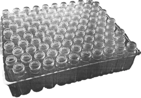
Waters sells the 350 pl vials in packs of 100, as shown in Figure 1-2. The vial is 12 mm in diameter and 32 mm in height. Vials are currently picked and placed into trays one at a time by unskilled labor. In addition to inefficiency, lack of quality control and validation methods have resulted in inconsistent final product quantities, which would increase the probability of breakage during transit. Moreover, hand packaging is prone to introducing external particulate containment into vials and would compromise the accuracy of results. Therefore, a more reliable and controlled packaging process is required to maintain Waters' standard in delivering high-quality products. Lastly, the QuanRecovery vial products are to be manufactured and packaged directly at the supplier's facility. This means Waters will not have direct supervision over the manufacturing process, nor can it monitor the manufacturing data from the process.
A
Figure 1-2: A tray containing 100 350 pl vials
The downsides of Water's current packaging methods prompted the company to enlist help from the 2019 MIT MEng cohort to develop an automated solution that would robustly place 100 vials into each container. This thesis describes the solution that was created to replace Waters' human packaging method.
1.2
Objective
The project proposed to design an automated system that would take loose state vials and correctly place them facing upwards in groups of 10 by 10 to fill a 100-vial container in a repeatable manner. The key objectives were as follows:
* Receive a bulk of unoriented vials and place them in a 10 by 10 matrix facing upwards in a vial package
" Package a minimum of 100 vials per 2 minute
e Validate that 100 vials are placed into each package
* Keep development and production costs under $10,000
1.3
Scope
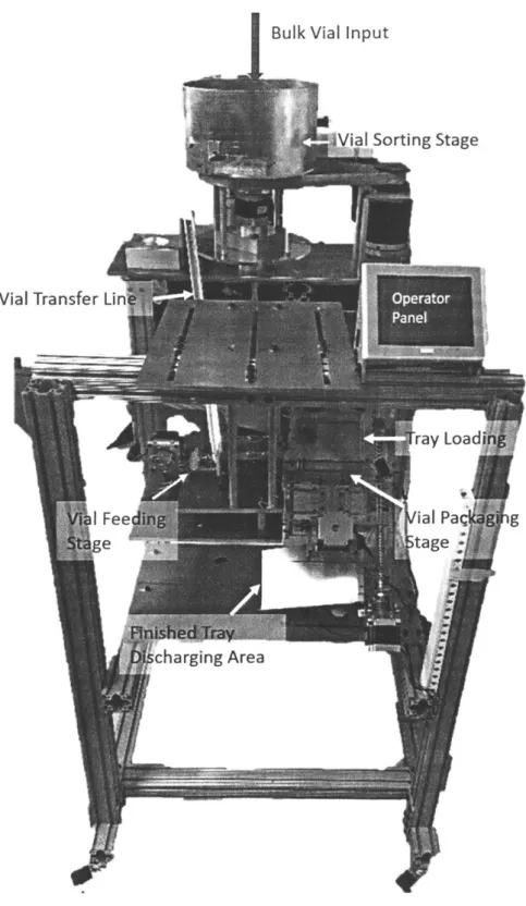
The project scope was contained to developing and building a functional prototype, displayed in Figurel-3 below, that could be used to demonstrate the potential for the proposed automated machine. Once the prototype was complete and working, engineering drawings of each custom component were made along with an assembly and user manual. This way, Waters could manufacture and operate future iterations of the machine as production levels deemed necessary.
1.4
Work Distribution
The system was divided into five main tasks as listed below:
1. Orienting vials from a bulk unorganized state
2. Feeding the oriented vials into the packaging mechanism
3. Packaging vials into trays
4. Validating vials are correctly placed within trays
5. Motor selection and system control
Initially, the team worked collectively on all tasks. After the inceptive brainstorm-ing stage was completed, each teammate took ownership of the task they selected. The owners of each task are as follows: (1) Zhengyang Zhang, (2) Efstratos Moskofidis,
Vial
Figure 1-3: Functional automated packaging machine prototype accepts bulk vials from the top, sorts the vials and outputs them to the transfer line. The transfer line is connected to a cam actuator that feeds the vials into the packaging stage. Operators can control the machine via a touchscreen panel
Chapter 2
Automation
This chapter presents a definition for automation; one that will be used as the premise for why the packaging machine creation is relevant in the 2 1st century. Furthermore,
the societal impact of automation is briefly explored.
2.1
Defining Automation
In the history of the manufacturing industry, the transition from hand-made to auto-mated work has taken many forms over the last quarter-century. Current buzzwords such as machine learning, data analytics, artificial intelligence and the Internet of Things
(IoT)
are redefining what popular belief would have once suggested was the face of automation: robotics. Even over the last five years, many questions have been raised on what truly defines automation and where it is going. In the workplace there are concerns over the ethics of replacing the human being with a machine. In the home there is concern over data collection and privacy, where both logical and physi-cal machines are recording what we say, tracking products and services we prefer, and tailoring the media we consume to our analyzed behaviors. It is easy to get lost in the many thousands of online articles warning of the impending danger of becoming a more mechanized civilization. However, from the perspective of an engineer, we must see the state of the art for what it is in order to extract from the hysteria the truly plausible implications of increasing automation.For the purposes of this thesis, automation will be defined as the use of a computer-guided mechatronic system to perform a physical task with little to no human inter-vention. The system may also collect data on its environment and respond to stimuli in that environment. However, it is not necessary for the system to do so in order to abide by this crude definition of automation. In this thesis we will focus specifically on what the human being relies on the machine to do and what types of mechanical intervention can be considered automation by this definition. We will explore the motivations for implementing physical automated systems on the factory floor and not software-only solutions such as data analytics and machine learning. These are for another technical discussion that is out of the scope of this particular thesis. For more detailed work on Industry 4.0 integration for this project, refer to Siyang Liu's
2019 thesis.
2.2
Reasons for Automation Implementation
Increasing throughput, reducing injury from repetitive motions or boredom, and mak-ing manufacturmak-ing less costly may immediately come to mind as the main motiva-tions for the manufacturing industry to implement automation. With a computer-controlled machine the benefits are nearly immediate to understand: the company no longer has to pay an employee's hourly wage, insurances or other benefits just so he or she can continuously perform a single task or flow of tasks. The employee may then seek more engaging, personally fulfilling or challenging work.
Chapter 3
System Overview
This chapter provides a synopsis of the vial packaging system's features, layout, and operation. Specifically, the system is broken down and detailed through its five prin-cipal components.
3.1
Vial Sorting and Orienting
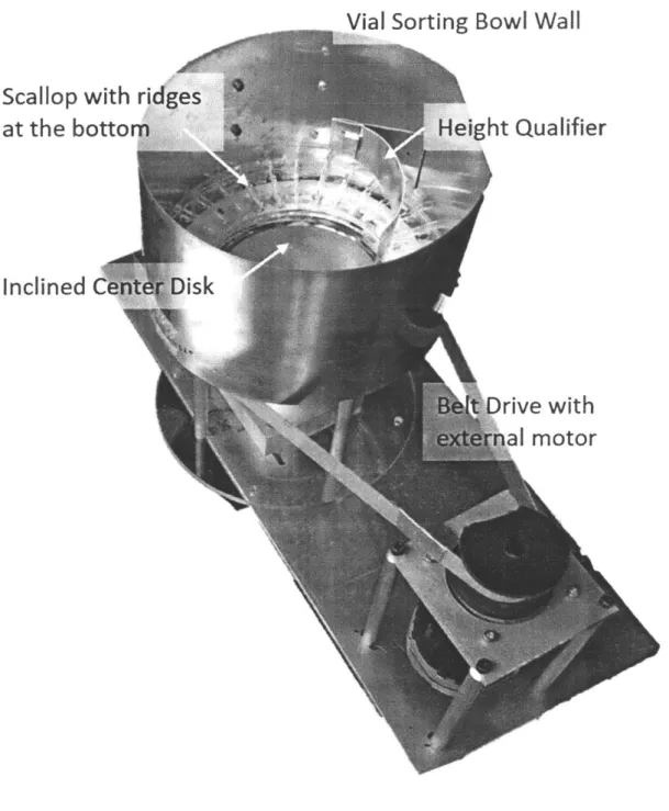
The vial sorting system is the first stage of the automated machine. It accepts loose vials in bulk and outputs singulated vials, all with the same final orientation. Figure
3-1 below displays the setup of the vial sorting system, resembling a bowl feeder.
The sorting system contains by three primary components: a center disk that accepts loose vials and transports them, a bowl with scallops that singulates vials, and various qualifiers that retain vials facing the desired orientation while rejecting the rest. The inclined center disk rotates, applies centrifugal force on vials, and propels them onto the scallop pockets. The bowl also rotates continuously and moves the vials past series of passive mechanical selectors which reject vials that are not properly nested within the scallops and not facing the right orientation. The rejected vials are returned to the center of the bowl and recirculated; the retained vials are pushed out of the bowl and move on to the transfer line.
Vial Sorting Bowl Wall
Scallop with ridges
at the bottom
Height Qualifier
Inclined Center Disk
Belt'Drive with
external motor
I
3.2
Transfer Line Feeder
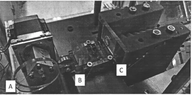
The transfer line feeder is the second stage of the automated machine. It receives sorted vials and transfers them to the vial packaging mechanism at the proper cadence and alignment. Figure 3-2 below displays the transfer line feeder.
Figure 3-2: Second stage of the automated packaging machine: A cam (A) is driven
by a motor and pushes vials in the queue forward via a pusher (B) one at a time into
the turner (C). Vials would take a 45 degree turn when exiting the turner.
The transfer line feeder contains three subsystems: a channel accepting vials from the sorting system and acting as a queue, a vial pushing mechanism that propels vials through a turner, and a turner that orients vials at the correct inclination to match with the placement mechanism's angle.
For more details on the transfer line feeder, please refer to Efstratios Moskofidis'
2019 Master of Engineering thesis: Design and Development of a Transfer System for
an Automated Packaging Machine[2].
3.3
Vial Placement Mechanism
The vial placement mechanism performs two primary tasks: loading the oriented vials into a tray and queuing empty trays to be loaded with vials. Figure 3-3 below displays
a diagram of the placement mechanism. giI~ CC-V e pA E trP ok
tcscet
4ffA4¾4kt~
44
P44 ;r+~
rr I LPositioned after transfer line feeder, the placement mechanism funnels a line of 10 vials into the rake. The cam applies force through a flexure, acting as a linear slide, to the rake. This force propels the rake forward, positions it over the tray, and allows vials to drop into their final placement. After each stroke of the rake, the tray slider
steps down to the next empty row, allowing the process to repeat.
When a tray is loaded with 100 vials, the tray slider moves down to the offboard ramp, where the full tray is able to slide out towards the vision system. After the full tray has been discharged, the tray slider resumes initial position; permitting the next empty tray to fall into place on the tray slider.
For more details on the vial placement mechanism, please refer to Steven Rat-ner's 2019 Master of Engineering thesis: Design and Development of a Placement Mechanism for an Automated Packaging Machine[3].
3.4
Motor Selection& Programming
The machine utilizes several motion axes to achieve reliable vial packaging. The following list describes all motors and actuators used on the machine:
1. Vial sorting bowl (center stage and sorting ring) - Teknic@ ClearPathTM
ser-vomotor with integrated motor controller
2. Vial sorting center disk - 24V DC stepper motor (direct drive)
3. Transfer line feeder - 24V DC stepper motor (operating a cam)
4. Vial rake - 24V DC stepper motor (operating a cam)
5. Tray lead screw - 24V DC stepper motor (direct drive)
6. Vial-biasing block - 120V AC linear solenoid
Sensors are placed throughout the machine layout to provide feedback on the machine's performance:
2. Vial counter: standard 24V DC optical sensor
3. Rake actuation counter: 24V DC microswitch, wired normally open
For details on motor selection and programming of the machine, please refer to Diarny Fernandes' 2019 Master of Engineering thesis: Design and Development of a Precision Packing Stage and Master Control System for an Automated Vial Packaging Machine[4].
3.5
Automated Inspection System & Connectivity
The last stage of the packaging machine is automated inspection and data transfer. The machine needs to produce exactly 100 vials packaged in a plastic tray in a ro-bust fashion. Therefore an automated inspection system is developed to confirm the correct number of vials in a package. In addition, Waters needs to keep track of the manufacturing data of the packaging machine since the packaging process happens at a remote location. Therefore a data delivery system is also developed to post opera-tional data in a server so that Waters can monitor the machine performance in real time.
The automated inspection system is enabled by a Raspberry Pi 3 Model B+ and a Raspberry Pi NoIR Camera module with infrared capability. As a completed package of vials exits the packaging stage, it enters a black box with the camera installed on the ceiling. The black box is selected in order to create a controlled lighting environment for the camera to deliver a robust performance. Both white LEDs and Infrared LEDs are selected to provide adequate lighting inside the black box so that the camera can capture all the features in the package. The Raspberry Pi is set up with Python 3 and OpenCV to run feature recognition algorithms.
uptime, the data will be sent through Ethernet to the Waters server for storage and inspection.
For a detailed overview of the motor selection and programming of the machine, please refer to Siyang Liu's 2019 Master of Engineering thesis: Design and Develop-ment of an Automated Inspection System for Vials[5].
Chapter 4
Sorting System Design
The design of the sorting system can be characterized as a centrifugal feeder that consists of a rotating center disk and a rotating bowl with scalloped surface. The function and design principles of major components of the system and are described in this chapter. The modular design of the machine allows easy maintenance and repair, short changeover time for different parts with similar size and shapes, and also re-tooling of the unit for future products.
4.1
Problem Statement
Design constraints are taken into account for the proposed solution. According to Waters, the desired solution will be operating in a cleanroom setting. Because of stringent cleanliness requirements for cleanroom, the production environment imposes various constraints on power, material, and processes. For instance, cleanroom air quality is expensive to deliver and maintain, so compressed air is not available because of the risk of contaminants.
Additionally, Waters utilized proprietary technology to coat the inner wall of vials, which results in superior performance over other competing products. Mechanical contact with the coating could lead to thinning or breaches, so any manipulation of vials are limited to the outside of the vial and away from the open cavity.
4.2
Design Principles
4.2.1
Vial
The QuanRecovery vial is a cylindrical sample container with a screw threaded neck. The vial is 12 mm in diameter and 32 mm in height. The open cavity of the vial has a diameter of 8 mm. Each vial weights approximately 2 gram, and the center of gravity is located at 12 mm from the base. The inner wall of the vial is tapered to help samples aggregated at the bottom, and for easy access of pipette tips.
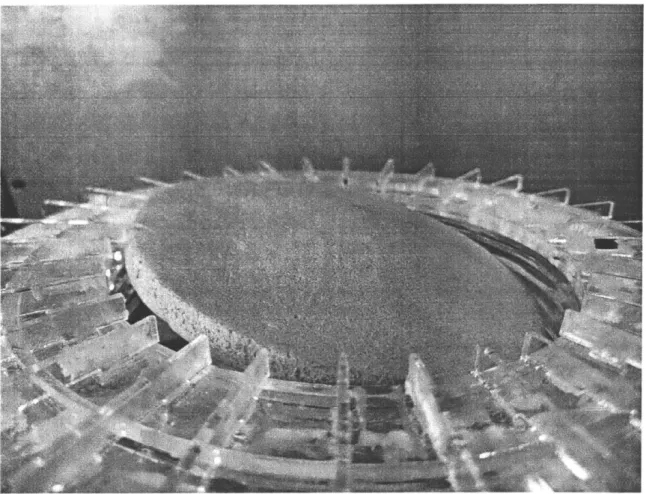
4.2.2 Center Disk
The center disk, as indicated by its name, is a cone shape platform positioned at the center of the bowl feeder. The center disk is inclined so only the top half of the disk are close to the rim of the bow, and the other half sits at the bottom of the bowl (See Figure 4-1). The inclined center disk acts as both a temporary reservoir for vials and a driver that propels vials onto the bowl. The angle of the center disk is generally between 20-30 degrees, depending on sorting part's physical characteristics, rotation speed, and scallop design. In addition, the center disk sits higher than the
scallop finger so the vials are falling from the disk onto the bowl instead of shooting in between scallops.
For single drive bowl feeder, the speed of the center disk is always coupled with the bowl. The bowl always moves faster than the center disk so that vials that are brought to the top of the disk can be quickly removed from the unloading area as. Speed is especially important for light-weight parts like vials, as a higher centrifugal force generated from spinning would cause the vials bounce too much on the track and discharge them in the incorrect orientation. High speed would also increase the risk of jamming vials between scallop fingers and qualifiers. The bowl runs the best
-4
Figure 4-1: Inclined Center Disk positioned at the center of the bowl
unloading and also increases number of parts that would be unloaded onto the bowl. Speed should be the last parameter to adjust when trying to increase the load effi-ciency of the scallop pocket.
4.2.3
Part Confinement with Scallop/Bowl
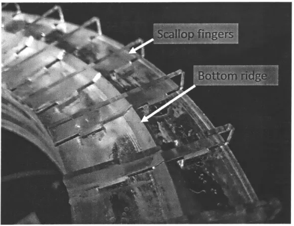
Unlike other centrifugal bowl feeders that have completely flat running surfaces for parts to slide on, the centrifugal bowl feeder has small vertical walls called scallop fingers on the surface of the bowl. Scallops are used to orient cylindrical parts that has a height to width ratio greater than 1.5:1. The scallop fingers are designed to isolate individual vials and constrain their horizontal movements after they get unloaded from the center disk.
the pocket and at the same time, expose the upper parts of the vials so they can interact with various qualifiers. The scallop pocket depth is between the dead center of the vial to the top side of open cavity. Additionally, for this particular machine, a ridge is designed at the bottom to further constraint vials and help retaining the ones in the correct orientation (See Figure 4-2). The cross-section of the ridge shapes like a triangle with the height equals to shoulder width of the vial when laying on the side. The hypotenuse of the ridge also later serves as a ramp that guides vials to exit the sorting machine.
Figure 4-2: Scallop fingers and bottom ridge confine the position of vials
4.2.4
Qualifiers
-4
the scallops pocket can interact with the selectors and qualifiers without jamming or interference. In addition, because mechanical tooling works passively to unscramble and align vials, they should be as gradual as possible to reduce jamming and damage to the parts. For this particular machine, because of the constraint on pneumatic power source, all qualifiers and selectors are purely mechanical.
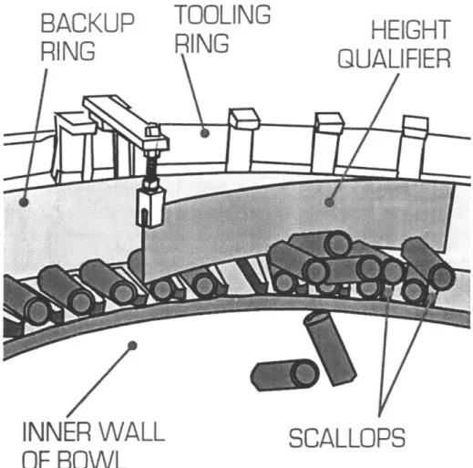
After the vials get unloaded form the center disk, they pass through height quali-fiers, that sits above the scallop fingers. There is a clearance gap between the height qualifier and scallop fingers for vials to pass through. Vials that are stacked on top of other vials will be rejected, pushed off the edge of the bowl, and land back into the reservoir at the bottom of the center disk. Figure 4-3 shows how qualifiers interact with vials[6].
BACKUP
TOOLING
HEIGHT
RIGRING
QUALIFIER
INNER WALL
SCALLOPS
OF BOWL
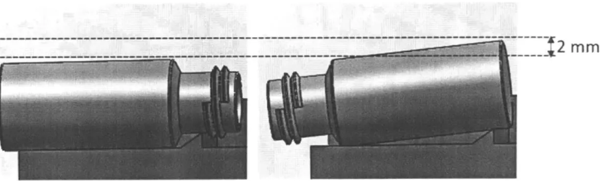
In addition to posting vertical constraints, different qualifiers have various func-tions. After height qualifiers have swept off excess vials, and all vials are singulated within each scallop pocket, another qualifier aligns the vials. As previously men-tioned, a triangle-shaped ridge is designed and installed at the bottom of the pocket to help anchor the vials that are in the right direction. Vials in scallop pockets would follow the curvature of the aligner and ends at designated position on the scallop. If a vial was facing the desired direction, the ridge would sit between the shoulder and the neck of the vial, and the vial would stay flush with the scallop fingers. If a vial is in an undesired direction, the body of the vial would sit on top of the ridge and raise higher than those in the desired direction (See Figure 4-4). The singulated, but mis-oriented vials will be rejected by another qualifier as any vials that sits higher would get swept towards the center of the bowl and back to circulation. Lastly, all the correctly oriented vials would move pass the last qualifier, the ejector. The ejector gradually close in the gap between it and the bowl wall. With the help from the bottom ridge, vials would get pushed out of the exit port and move on to the transfer line for the next stage.
--- - 2 mm
Figure 4-4: A schematic showing the two positions of a vial sitting within the scallop pocket
4.2.5
Driver
chains and sprockets and driven by a single motor. A pre-determined speed ratio is maintained by the number of teeth on sprockets. Although a timing belt and pulley can also be used to drive the bowl, they are eliminated from consideration because belt would generate dust, which is undesirable in clean room environment. In dual-drive feeders, the center disk and the bowl body are dual-driven independently. Dual-dual-drive feeders have a higher degree of flexibility as the speed ratios can be changed freely as needed.
The prototype adopted the dual-drive design for ease of testing. A pillow block bearing is installed at the center of the bowl, and a motor is placed at a distance to the bowl and drives it via a custom made belt. Sitting in the center of the bowl and within the bearing is a smaller motor that remains stationary. The shaft of the motor directly connects with the center disk and rotates around its own axis.
Chapter 5
Prototype and Final Design
A total of two designs were made for the machine. Owing to manufacturing
limita-tions, the first design is a small-scale version and serves as a proof-of-concept. After validating the concepts and functions, a full-scale design using engineering materials was proposed and will be implemented as the final solution.
5.1
Prototype Assembly
The prototype is made out of various materials that are most suitable for manufac-turing processes that can be leveraged (See Figure 5-1). The main body is made out of acrylic from laser cutting, and therefore the size of the feeder is limited by the working table of the laser cutter. The bowl has a diameter of 9.5 inches. 1/4 inch thick acrylic was cut to circular shape and laminated together to build up height. Scallop fingers are also individually cut using 1/8 inch thick acrylic and inserted into the top surface of the bowl body, which has slot cut-outs. Glue was applied for re-inforcement. Four columns were attached between the bowl body and the base plate to further heighten the feeder and create space for positioning of the center disk.
Scallop with ridges at the bottom
Vialsorting bowl wall
-Inclined c
151Inches
i-~j
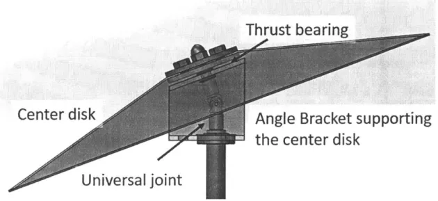
The center disk was made out of insulation foam because the center disk is sup-posed to be light weight yet firm enough to support the vials. While thermal-forming was initially considered, it was eventually eliminated due to relatively long mold-making process. To angle the center disk and maintaining its rotation independent from the bowl body, a combination of a universal joint and an angle bracket is used to provide inclination and also support (See Figure 5-2). The bottom of the angle bracket is attached to the center motor which spins the center disk. The independent rotation of center disk from the bowl is achieved through a bearing. The pillow block is attached to the base of the bowl, and the center motor sits in the inner ring of the bearing. The bowl body is driven using a belt drive with a motor positioned at a distance to the bowl. A pulley is machined and have a diameter ratio of 4:1 with the bowl body.
Thrust bearing
Centerdisk
Angle Bracket supporting
the center disk
Universal
joint
Figure 5-2: Angle bracket and universal joint
The bowl wall is made of rolled sheet metal and riveted together. It's also attached to a post that hovers over the bowl body. On the bowl wall, various slots were cut out for attachment of qualifiers. Qualifiers are sheet metal strips rolled and bent. The exact selector curvature dependents on the function and the size of the bowl feeder as the transition need to be as gradual as possible to avoid any jamming.
5.2
Prototype Testing and Performance
Once the machine is fully assembled, the performance of the machine can be tested. Due to the size limitation of the small-scale prototype, not all functions are realized at the same time. Individual components have to be tested separately. The goal of the test is to demonstrate the viability of each function of the bowl feeder and show that the same mechanism can be applied to a full-scale design.
Being able to singulate and orient vials is the most critical module of the system. It is essential that the interaction between qualifiers and vials is as gradual as possible to prevent jamming, therefore, qualifiers are generally long and take up a lot of space. The size of the prototype limits the number of qualifiers that can be fitted on the bowl wall at the same time. To accommodate the prototype, two qualifiers were tested at a time during the validation test. In addition, because the low capacity of the center disk reservoir, the number of vials delivered to the scallop could not reflect the work load on qualifiers. So, the qualifiers were tested independently from the center disk.
The first two height qualifiers were first tested. A load of vials was randomly stacked on the scallop simulating the condition after the vials land from the center disk. Then the motor was initiated to rotate the bowl. In the first attempt, jamming occurred at the first height qualifier because the qualifier forms a right angle with the vials and completely constrains them with the scallop fingers. Also, the clearance was too small between the first height qualifier and scallop fingers, which are much
less forgiving and increase the possibility of jamming.
In the second iteration, the function of sweeping off excess vials was allotted to two consecutive height qualifiers with decreasing gaps between the scallop finger. In addition, the first height qualifier was modified so that it also curved and gradually redirect vials back into the circulation. With the modification, the first height qualifier was able to sweep off most of the vials that are stacking on top of each other, with some
A
Bowl rotate direction
Rejected vial direction
Height qualifiersStcevis
Figure 5-3: Height qualifiers sweeping off excess stacked vials
and the second height qualifier should be small to ensure no vials are sitting on top each other, enough room still should be left as singulated vials would still sit higher than scallop fingers because of ridges at the bottom of the pocket.
The testing of the last two qualifiers were uneventful. The gradual curve of the aligner pushes vials toward the center of the bowl feeder. For the vials that are facing the desire orientation, they would lodge onto the ridge at the bottom and lay flat, whereas the ones facing the wrong orientation would get push off the scallop into the center. Finally, the last qualifier ejects the retained vials that are facing the correct orientation to the next stage.
The maximum speed for bowl feeder is determined from a parametric study in last test. Initially, the motor was ran at 30 rpm and the oriented vials were smoothly exiting the bowl. Then, the speed was increased at 5 rpm increment until jamming occurs. When the motor was running at the 50 rpm, the ejector was not able to quickly direct the vial out of the bowl, and the vial would be clamped between the ejector and the scallop wall. This test shows that if the bowl is not under a high production pressure, the speed setting should be set in a slow range to ensure proper functioning of the qualifiers.
vial exiting the bowl
Figure 5-4: Oriented vials exiting the sorting machine
The ideal situation is that as the center disk rotates and continuously brings the vials from the bottom to the top, the vials would roll and fall onto the scallops and get transported. However, a difficulty was experience during testing of the center disk because there is a significant gap between the disk and the vial, and some vials would fall through the gap before landing onto the scallop. This is caused by a combination of misalignment and inaccurate disc size. To address this issue, the incline angle was
adjusted. As the speed increases, the landing of vials became more violent, bouncing occurs at 60 rpm. One thing worth noting is that given the size limitation, the capacity of the reservoir is significantly compromised, and the actual performance of the center disk needs further testing on the full-scaled one.
5.3
Final Design
With experience gathered through testing of the prototype, the final full-scale digital model of the feeder is designed in SolidWorks. The bowl has a center disk of 2 feet in diameter, and is surrounded a 3' by 3' square T-slotted frame (see Figure 5-5).
To satisfy the need to sort over 100 vials per 2 minutes, the bowl needs to have a large reservoir to hold enough vials and also many scallops to accept the vials. Because qualifiers only retain vials that are in the desire orientation and does not actively correct the orientation, the output of the bowl feeder is stochastic in a short time period. Therefore, increasing the size of the bow feeder helps increasing the number of vials that get retained within the scallop pockets.
The bowl wall surrounds the bowl and is anchored on the top surface of the square frame by brackets. Slotted struts are also attached to the bowl wall and provide support for tooling ring, on which various qualifiers would be attached. Unlike the prototype, qualifiers are not directly attached to the bowl wall but instead mounted on the tooling ring that sits above the bowl wall. The strut allows course adjustment of the overall qualifier heights, and the finer height and horizontal adjustments can be made on the qualifier gantry.
Within the bowl wall sits the bowl body and the center disk. The bowl wall and qualifiers remain stationary whereas the bowl body and center disk rotate. For ease of manufacturing and assembly, scallops would be made out of soft plastic like Delrin and secure onto the bowl through countersink screws. Due to the large diameter, the scallops can be segmented into 10 identical pieces and assembled together. Within the lower half of the bowl body, a curved bowl skirt is installed to close the gap between the trough of the center disk and the bowl. The bowl body is not in contact
Support structure
Figure 5-5: Isometic view of the final design CAD model
with the bowl wall and is supported by structures mounted at the base plate. The base plate sits within the frame and provides support for majority of the machine, including bowl body, center disk, and drive train that powers them.
Because the bowl and the center disk have a fixed rotation speed ratio, they can be driven by a single motor via sprocket and chains. The main sprocket is attached to the spindle hub located at the center base plate. A turntable sits between the spindle
Vileservoir AngeI bracket Bo Il Skirt Adjustable support +Trtable Motor
Figure 5-6: Side view of the final design CAD model
hub and can be used for fine adjustment of the levelness of the bowl. The center disk is supported by four separate columns and rests on a 20-degree angle bracket. A universal joint connects the center disk and a center shaft that runs through the angle bracket and the center of the spindle hub. The shaft is driven by a different size sprocket within the drive train and controls the speed of the center disk.
Chapter 6
Conclusions, Recommendation,&
Future Work
6.1
Conclusion
An automatic vial sorting and orienting system was designed for this project. A small-scale prototype was built to show the feasibility of the machine, and a final full-scale solution was provided. The testing of the prototype has showed that:
" Rotational motion works well for sorting and orienting regular-shaped, light
weight vials.
• The physical characteristics of the vial were well leveraged by various features of the machine during the sorting process. The vials are constrained securely within the scallop pockets and by bottom ridges.
• Qualifier height is a critical dimension that ensures qualifiers to function prop-erly. The contact area between qualifier and vials is small, so if the installation of the qualifiers was imprecise, the qualifiers could either miss the vials or in-crease jamming possibility.
" The maximum operation speed is determined by the size of the bowl and the
larger diameter. Long contact time with qualifier and gradual qualifier curvature would lead to a smoother interaction with vials. Speed exceeding certain range would resulting vials jamming between ejector and scallop fingers.
6.2
Recommendation& Future Work
Although the small-scale prototype has demonstrated the working principle of the rotary feeder, tuning is still required after the construction of the final machine as significant changes were made to accommodate the size and the structure rigidity. The manufacturing method for some specific components are still open to discussion. For example, the current plan to manufacture the bowl body is to weld a flat ring to a rolled sheet metal, and the bowl skirt would be made from metal spinning. How-ever, fabricating custom sheet metal parts, particularly circular parts, could lead to relatively large error bounds as compared to machining and turning. One alternative method is to cast the entire bowl out of aluminum and post machine for a higher tol-erance. The most obvious trade-offs for that are cost and lead time, and that would be Waters' decision to determine which factors do they deem the most important.
A parametric study is called for to determine the optimal rotational speed,as the
linear velocity at the edge of bowl would be much larger than that of the prototype. The optimal mounting positions of the qualifiers also require additional investigation as there are more space within the bowl to work with.
While the design of the machine has satisfied the basic functional requirements, ad-ditional improvements can be made to improve robustness and fluency of the process. In the entire sorting and packing process, the bowl feeder has the highest throughput, and therefore blockage would occur when downstream transfer line is filled. Current solution for blockage is to stop the machine entirely; however, frequent re-start of the bowl feeder could lead to unpredictable behavior of the vials that are passing through
To better predict the behavior of vials on the center disk, it's preferable to control the number of vials in the reservoir at a given time. Currently the vials are manually loaded onto the disk in batches as they come out of the previous process. As the number of vials on the center disk changes, the force they experience would change as well. It would be desirable to implement a pre-feeder that can regulate the amount of vials and deliver interval for the optimal performance of the feeder.
Appendix
A
Engineering Drawing
Exploded views, bill of materials, and engineering drawings of major components of the machine are included in this section.
H G F E D C B 12 1 11 | 10 1 9 | 8 1 7 | 6 1 5 | 4 1 3 | 2 1 1 H G
ITEM NO. PART NUMBER DESCRIPTION QTY.
1 Bowl Custom Part
2 Bowl Wall Custom Part
3 2313N250_CORNER MACHINE BRACKET Comer Bracket B
4 47065T601 T-Slotted Frame 4
6 spindle Custom Part I
7 scallop Custom Part
8 33085T762 Strut Channel 4
9 33125T1 Strut Connector 4
10 95505A615 Hex Nut 17
11 90322A165 Threaded Rod 4
12 Tooling ring Custom Part
13 33085T762 Strut Channel 8
14 33125T851 Strut Connector 8
15 47065T245 8020CornerConnecto 4
16 47065T332 8020 Angle Connecto B
17 47065T601 T-Slotted Frame 4
18 bowl skirt Custom Part 1
19 92240A462 Hex Screw 15
20 95505A616 Hex Nut 16
21 92240A248 Hex Screw 9
22 92210A539 Flathead Screw 40
23 92147A035 Split Lock Washer 8
24 92240A460 Hex Screw 8
25 91855A520 Tumtable 40
26 selector Custom Part 4
04 lie g C B F E D
12 | 11 1 10 1 9 | 8 1 7 1 6 1 5 1 4 1 3 | 2 | 1 6z9 Gs Spindle Assmebly A H G F E D C B
ITEM NO. PART NUMBER DESCRIPTION QTY.
I sprocket hub Custom Part
2 2737T906 Sprocket 1
3 Base plate Custom Part
4 6236K359 Sprocket 2
5 7200Kl Motor
6 off-center rod Custom Part 1
7 6236K351 Sprocket 2
8 5909K36 Thrust Bearing 1
9 needle bearing bed Needle Bearing
10 6261K238 Chain 172
11 18635A520ROUND TURNTABLE Turntable 1
12 60225K21 Tensioner 2
13 6663K22 Idler Sprocket 2
14 center -disc Custom Part 1
15 92865A352 Hex Screw 4
16 6384K373 Flange Bearing 1 H G F E D C B A
12 | 11 1 10 | 9 | 8 1 7 | 6 1 5 | 4 1 3 | 2 | 1
0
0
ITEM NO. PART NUMBER DESCRIPTION QTY.
1 selector head Custom Part 1
2 90322A666 Threaded Rod 1
3 95462A505 Hex Nut 4
4 selector mount flat Custom Part 1
5 selector basre Custom Part 1
6 selector slot Custom Part 1
7 92865A010 Hex Screw 1
G F E D C B H H G F 01, E D C B
3
029.00 0.005 //0.010 A 0 180 0 0.266 x 40 024.00-x
Notes:1.Material: 0.075" stainless steel sheet metal
UNLE5 OTHERWESPECFVED: NAME
DATE MIT 2019 ME MEng
DIMENS A IN WN-H( s DPAWN
1
P 07/15/19 M
FRACTIONALt CHECrEo TITLE:
1ENEr A t(0MFeederBowl
INTERPRET GE-MERK GA
TO1LEPANCII W M IG PAE1it
MATRIA SIZE DWG. NO.
REV
B
A
SCALE: 1:5 IGH : |SHEET 1(OF 1
4CLE
3: 2EIHT
4
B
2
o6,1
B
8-A
A
43
2 12
92.05
Drill size 19/32" Through hole X8
- -I. 0 (Y) 0 VA) z 0 0 Notes:
1.Material: 0.0325052 Aluminum sheet metal
URESSOTHERWBESPECD: NAME DATE M
DME1NS ARE iNINCHES DPAWN PZ 07/15/19 MIT 2019 ME MEng
FEACTONALI CHECKED TITLE:
AN4G'LAP'.MACHE t ENDI
TWO PLCE DECMAL END AFAR.Bo vI
aI
3
4 --CN (N1
B A 0 2.52 B A |I0
0
00
4b 0 I O0 O0 0 i1 0 83
2
1
1.440 k2.p~5.azz ~
0, 01 (N NOTES:1. Material: 0.00325052 Aluminum sheet
tJ*&ESS OTHERWISESPECFIED:
DIMEWN51NARE WNIWHts
WCER G& E11C RATRIALt
CWOPLACE EAL Alr 0
4
3
2
IWAE 0 DATE M
DPAWN | PZ 107/15/191 MIT 2019 ME MEng
TITLE:
Bowl Skirt
SIZE DWG.NO. REV
B A
SCALE: 1:10 EIGHT: SHEET 1 OF T
1
4
B
CT11 Vq,A
B
A
CHECrEC G.A. C OWAE Wt: 43
28 | 7 6 1 5 | 4 3 1 2 1
8
c6
04
Notes:
1. Material: 0.13"thick Aluminum
2. Manufacturing Process: Rolling and welding
UVEWJN AR N tLWI E BR SHRP DO NOIGCA E DRAWI P14GIO
&IKACEP~r-EDG:ES
F
E
C;'D
F
E
D
C
B
C
C)
B1
7
I
6
I
5
I
4
I
3
1
2
C..
UNISS XHEW " SP, MI. .IS: r'EfRRADDONO)F XALE DRAW IG PE r; TOLE"EDGES
ANGULAR:
4AE SIGNAoPE DA1 E LE
cr --w -
g
Center Disk
APPV" MFGA3 77,7 MAE7AL DWGN . F8
F
E
'0 CN0 1 C.,,D
F
E
D
CC
B
A
20I
B8
|
7
1
6
5
4
1
3
2
|
1
0.50 ° -611 0 0.52 1.50 CCll 2.50 2.50 CDDMENWJNS ~ ~ ~ ~ D NRE IN UMER KKSAFw .rcALE DRA WING PErN
F
E
CR °°D
IF
E
CN Lf) ,~t C 4.00C
B
D
C
B
8
|
7
I
6
|
5
|
4
|
3
|
2
I1
1/4" Countersink Through Hole X 4
024.00 o o
F
E
D
C
FNSH:AK Rui OONO TCALELWAW 3 PEv1N
S A ME SGNTUR DA EDE
1/10 Scallop
____"D -Segment DelrnF
E
C.,,D
C
B
A
83
BBibliography
[1] Linkedin. Waters corporation. https://www.linkedin.com/company/waters, June 2019.
[2]
Efstratios Moskofidis. Design and development of a transfer system for an auto-mated packaging machine. Master's thesis, Massachusetts Institute of Technology, Department of Mechanical Engineering, May - August 2019.[3]
Steven Ratner. Design and development of a placement mechanism for an auto-mated packaging machine. Master's thesis, Massachusetts Institute of Technology, Department of Mechanical Engineering, May - August 2019.[4] Diarny Fernandes. Design and development of a precision packing stage and master control system for an automated vial packaging machine. Master's thesis, Massachusetts Institute of Technology, Department of Mechanical Engineering,
May - August 2019.
[5] Siyang Liu. Design and development of an automated inspection system for vials.
Master's thesis, Massachusetts Institute of Technology, Department of Mechanical
Engineering, May - August 2019.
[6] Shibuya Hoppmann.
fs-60-scallop-centrifugal-feeder-installation-maintenance-manual. www.ShibuyaHoppmann.com.