Design for Manufacturing Analysis on the
Small Unmanned Ground Vehicle
By Ada Yu
B.S. Engineering and Applied Science, California Institute of Technology 2003 Submitted to the MIT Sloan School of Management and the Department of Mechanical
Engineering in Partial Fulfillment of the Requirements for the Degrees of
Master of Business Administration And
Master of Science in Mechanical Engineering
In conjunction with the Leaders for Manufacturing Program at the
Massachusetts Institute of Technology June 2008
C 2008 Massachusetts Institute of Technology. All rights reserved
Signature of Author
75
Department of Mechanical EngineeringMIT Sloan School of Management May 9, 2008
Certified by .
CeriEe bh itney, Thesis Supervisor
Senior Lecturer in Engineering Systems Senior Research Scientist, Center for Technology, Policy, and Industrial Development Certified b
Ro4 E. Welsch, Thesis Supervisor Professor of Statistics and Management Science Center for Computation Research in Economics anIanagement Science Director
Accepted by
Accepted by
Lallit Anand, Graduate Committee Chairman Professor of Mechanical Engineering
I Debbie Berechman
--- - - -ifixiP Th;rimotnr n-f A L PAR P. n am L A TL T 4ZJJ. n Ca Q nl nf Ja. n -rnaLint
MASSACHMMSETS INSTIUE.
OFTEOHNOLOGV
JUL
2 9 2008
BIL RARIES
~AVVUCIV~ UIIVVLVL VI I*lUII I ~V61CUII) 1*111 UIVUII U~IIVVI VI I*ILUILl~j~lll~llL
Design for Manufacturing Analysis on the
Small Unmanned Ground Vehicle
By
Ada Yu
Submitted to the MIT Sloan School of Management and the
Department of Mechanical Engineering on May 9, 2008 in Partial Fulfillment of the Requirements for the Degrees of Master of Business Administration and
Master of Science in Mechanical Engineering
ABSTRACT
iRobot is responsible for delivering the Small Unmanned Ground Vehicle (SUGV) as part of the U.S. Army's Future Combat Systems (FCS) initiative. With increasing external competition and pressures, iRobot must deliver an innovative robot while reducing costs, improving quality, and shortening the product's time to market. Since 100% of iRobot's manufacturing is outsourced, the SUGV manufacturing team must optimize its mechanical design in order to help ensure a smooth handoff between its design team and its contract manufacturer.
To achieve this goal, the SUGV manufacturing team utilized a Design for
Manufacturability and Assembly (DFMA) analysis to simplify components, reduce assembly steps, and improve processes. This paper describes the benefits of DFMA and the tools and techniques used in conducting this analysis. By studying mechanical assemblies, reviewing design drawings with the engineers, and gathering best practices from other industries, this paper provides recommendations for design changes on the SUGV and organizational strategies that can help improve iRobot's product development process.
Thesis Supervisor: Daniel E. Whitney
Title: Senior Lecturer in Engineering Systems
Senior Research Scientist, Center for Technology, Policy, and Industrial Development
Thesis Supervisor: Roy E. Welsch
Title: Professor of Statistics and Management Science
Director of Center for Computation Research in Economics and Management Science
Acknowledgements
First, I would like to thank iRobot Corporation and the Leaders for Manufacturing Program for providing me with the opportunity to carry out this work.
Specifically, I would like to recognize my supervisor, Rick Robinson, and my thesis advisors, Daniel Whitney and Roy Welsch, for their valuable feedback and guidance throughout the past year.
Finally, I am grateful for my family, LFM classmates, and my coworkers at iRobot for their endless support, laughter, and encouragement.
Table of Contents
1 Introduction ... 11
1.1 Internship Description and Goals ... 12
1.2 iRobot Company Background... 13
1.3 Packbot... 14
1.4 FCS Program ... 15
1.4.1 SUGV ... 16
1.5 Challenges... 17
1.5.1 Defense Contracting ... ... 17
1.5.2 Reliance on External Funding ... ... 18
1.5.3 100% Virtual Manufacturing ... ... 18
1.5.4 Balancing Innovation with Standardization... 20
1.5.5 Contract Manufacturer Selection and Timing... 21
1.6 Summary... 21
2
Product Development Process
...
22
2.1 History ... 22
2.2 Concurrent Engineering (CE) ... ... 23
2.3 DFMA ... 24
2.4 Case Study - Dell Computers... 26
2.5 Summary... 28
3
DFMA Analysis and Results ...
29
3.1 Structure of SUGV... 30 3.2 Key Characteristics ... 33 3.3 DFA Software... 38 3.3.1 Inputs ... 39 3.3.2 Outputs ... 43 3.4 Results ... 46 3.5 Summary... 47
4
Extension of DFMA Analysis ...
48
4.1 Designing Balanced Assembly Line ... ... 48
4.2 Data Collection for Reliability ... ... 48
4.3 Manufacturing Process Roadmap ... 49
4.4 Summary... 50
5
Evolution ...
51
5.1 Product Platform... ... 52 5.2 Low-end Market ... 53 5.2.1 Market Size ... 53 5.2.2 NPV analysis ... 545.4 Summary ... 55
6
General Recommendations ...
56
6.1 Leveraging Complementary Industries ... 56
6.2 Select CM Early... ... 56
6.3 Become Proactive... 56
6.4 Ensure Equal Input From the Manufacturing Team ... ... 57
6.5 Summary ... 58
Appendix 1. Assembly Flowcharts ... 59
Appendix 2. Designing Balanced Assembly Line ... 64
Table of Figures
Figure 1. iRobot SUGV ... 12
Figure 2. Company Overview ... 14
Figure 3. Side by side comparison of the Packbot and SUGV ... ... 15
Figure 4. The over-the-wall design method [Ullman]... 22
Figure 5. Benefits gained from implementing concurrent engineering in 150 companies... .. 24
Figure 6. Part count reductions from 43 published case studies where DFMA methods were used since 1990. ... 26
Figure 7. Cost Breakdown for Packbot ... 30
Figure 8. SUGV Main Subassemblies ... 31
Figure 9. Main Liaison Digram ... 31
Figure 10. Chassis Liaison Diagram ... 33
Figure 11. Battery to PCB Datum Flow Chain ... 34
Figure 12. Datum Flow Chain for Power Delivery to Actuators ... ... 35
Figure 13. Electronics Assembly into Housing ... 38
Figure 14. Boothroyd and Dewhurst DFA Software ... 39
Figure 15. Sample output of Boothroyd Dewhurst DFA Software ... 45
Figure 16. iRobot Packbot and former competitor Robotic FX Negotiator ... 52
Figure 17. Projected Number of Users ... 53
1 Introduction
Today's technologically-savvy customers demand complex products that are low cost and high quality. In the nascent market of personal and service robotics, a company like iRobot must find ways to deliver innovative products to satisfy these customers. Innovation, by nature, induces risks and variability. Coupled with the simultaneous objectives to lower costs and improve quality, designing elegant and innovative robots with increasing complexity poses a significant challenge. This challenge is exacerbated by the growing competition in the worldwide markets, the often ill-defined organizational structure, and the premature technological state of the emerging robotics manufacturers.
Every manufacturer strives to lower production costs and attain quicker time-to-market. Because an estimated 80% of all manufacturing costs are determined by the time design drawings and specifications are complete [1], products must be designed properly from the beginning in order to avoid cost overruns at later stages. Designers must
identify manufacturing issues early in the design process and develop solutions to control and mitigate any production risks. Thus, to have a properly designed product, a company must coordinate the interaction and cooperation among production, engineering, quality, and marketing teams from the very beginning of the product design and development cycle. By simultaneously focusing on every aspect of the product from functional requirements and material selection to tooling and assembly procedures, this strategy of concurrent engineering enables the company to achieve its cost and quality goals.
iRobot Corporation is no exception. For its products to continue to be
competitive worldwide, designers must deliver innovative products at low cost and high quality. Designers and manufacturing engineers must work closely together and focus on
manufacturability and assembly issues from the beginning of the product development cycle.
1.1 Internship Description and Goals
iRobot's Small Unmanned Ground Vehicle's manufacturing team is preparing to launch a cutting-edge tactical and reconnaissance robot for the U.S. Army's Future Combat System. (See Figure 1. iRobot SUGV) The first-pass design of the SUGV, while incorporating some manufacturability features, had not been formally evaluated for design for manufacturability and assembly (DFMA). To optimize producibility and minimize cost, iRobot wants to perform a comprehensive review of the existing design and present improvement suggestions for the next design cycle.
Figure 1. iRobot SUGV
The 2007 LFM internship was designed to carry out a DFMA analysis on the SUGV. The internship focused on conducting a DFMA analysis on the SUGV by studying the mechanical assemblies, reviewing the design with the engineers, and gathering best practices from other groups, companies, and industries.
The main goals of the internship were to study and analyze iRobot's development process and product in order to:
* Influence design change (i.e. reducing part-count, simplifying assembly process) to lower manufacturing and maintenance costs while improving the quality of product.
* Aid in the design and development of an efficient assembly line with thorough analysis of assembly sequence.
12
* Identify software tools to better collect and analyze reliability data once the SUGV goes into production.
* Produce cost-savings data to provide incentives for management to invest in initial tooling costs.
This thesis is the result of the 6-month internship with the SUGV team at iRobot Corporation. After reviewing the company's strategy, culture, and product development process, the thesis presents a DFMA case study from the computer industry. Next, the thesis provides a detailed analysis of the tools and techniques applied to assess the manufacturability of the SUGV and the results that can improve the quality and reduce the cost of a product. Then, an extension of standard DFMA practices looks at how data can further help improve iRobot's product development process as a company. Finally, the thesis discusses possible future roles for the SUGV.
1.2 iRobot Company Background
iRobot was founded in 1990 by three Massachusetts Institute of Technology roboticists: Colin Angle, Helen Greiner, and Dr. Rodney Brooks. iRobot specializes in delivering behavior-based robots that can navigate in complex and dynamic real-world situations in order to help people complete mundane or dangerous tasks. The company's objective is to rapidly invent, design, market and support innovative robots that will expand iRobot's leadership globally in existing and newly addressable markets.
iRobot is organized into two main divisions: Home Robots and Government and Industrial (G&I). In 2007, the Home Robots had revenues of over $227.5 million and G&I won contracts awards of $21.6 million. [14] The Home Robots Division is focused on selling both indoor and outdoor cleaning robots to household consumers, offering popular products such as the Roomba floor vacuuming robot and the Scooba floor washing robot. To date, more than 2.5 million Home Robots have been sold worldwide.
[14] The G&I Division oversees all aspects of military products and contracts. G&I products are typically manufactured at low-volumes and are highly customizable. Over
1,200 iRobot PackBot Tactical Mobile Robots have been deployed around the world to aid in missions for military and civil defense forces.
Being a relatively young company that is rapidly growing, iRobot is always in a state of flux. Figure 2 summarizes iRobot's vision for itself - to change the world while having fun by building cool stuff, delivering great products, and making money.
iRobot's customers provide a feedback loop that influences the design of iRobot
products. With a great lineup of new and exciting products, iRobot has already changed the way the world views robots.
Figure 2. Company Overview
1.3 Packbot
In 1998, iRobot received a DARPA contract for the tactical mobile robot program and became responsible for the development of the PackBot. The PackBot had three
notable achievements in the 2001-2002 timeframe that brought fame and popularity to these military robots:
* Searched the rubble of the World Trade Center in New York City after the September 11 terrorist attacks (September 2001).
* Searched caves in Afghanistan for ammunition and hostile forces (June 2002). * Searched the Great Pyramids of Egypt on National Geographic (September 2002).
The Packbot product line continues to prove its usefulness in performing missions around the world. Currently, there are an estimated 5,000 robots of various types
deployed in Iraq and Afghanistan -- up from 150 in 2004 -- with $1.7 billion earmarked for ground-based military robot. With an estimated 70% of all US causalities in Iraq caused by road-side bombs, the bomb-detection PackBots are highly valued.
As a result of the success of the Packbot, iRobot won an additional contract to be the prime the developer of a Small Unmanned Ground Vehicle (SUGV) for the U.S. Army's Future Combat Systems (FCS) program in 2004 (Figure 3).
Figure 3. Side by side comparison of the Packbot and SUGV
1.4 FCS Program
The Future Combat System (FCS) program is a $108 Billion Department of Defense program. Its goal is to transform the Army to become a strategically responsive and dominant force capable of meeting the challenges of the 2 1st century. To create new sources of military power that are responsive, deployable, agile, versatile, survivable, and
sustainable, FCS uses a combination of advanced technologies, organizations, people, and processes. Four out of the twelve vehicle systems being developed under the FCS program are unmanned vehicles requiring advanced robotics technologies. [2] This cutting-edge development requires the need for sound manufacturing environments to ensure product quality, availability, cost, and continuing innovation.
1.4.1 SUGV
The Small Unmanned Ground Vehicle (SUGV) is designed to be the "soldier's robot" - a light-weight, tele-operated, man-portable robot that will support
reconnaissance and remote sensing in rural and urban terrain. The system needs to be highly mobile for dismounted forces and re-configurable by adding/removing sensors, modules, mission payloads, and/or other subsystems. The usage of the SUGV minimizes the risk to soldiers during hostile urban and mountainous operation, provides real-time intelligence and complete situational awareness, and enables navigation into collapsed buildings and other inaccessible areas such as tunnels, sewers, and caves.
Lighter, smaller, and faster than a Packbot, the SUGV is designed to perform a wide range of tasks by attaching different mission payloads of various sensors and arms. The SUGV is waterproof and shock resistant. It fits into the standard army backpack, and operates in a harsh environment. The battery-powered SUGV is operated wirelessly, or via a fiber optic cable, using a controller that looks like a video game controller with a built-in video screen. Like the PackBot, SUGV climbs stairs, maneuvers over rubble and different terrains.
The SUGV is designed to perform outpost missions, a dangerous job the infantry is glad to be able to "send the robot first". Other roles for the SUGV include placing explosives by a door (to blow it open for the troops), or placing smoke grenades to prevent the enemy from seeing the troops move. iRobot works closely with soldiers in the field to get feedback from field testing to change and improve on the usability and functionalities of the SUGV. It is no surprise that soldiers value these robots want more of them working in the field.
1.5 Challenges
iRobot faces significant challenges in developing and manufacturing the SUGV. While a commercial project can set its priorities and make tradeoffs between costs and functionalities, the SUGV team must meet all of the government's functional and quality specifications at the lowest cost. In addition to the risks associated with defense
contracting and outsourcing, iRobot must also manage the challenge of maintaining a startup culture in a growing organization.
1.5.1 Defense Contracting
The SUGV program is funded by the Department of Defense (DOD). Under the defense contract, the SUGV program is held to an additional set of constraints with more stringent requirements, restrictions to outsourcing overseas, and more demanding
approval processes for all lower-tier suppliers and assemblers.
There are three types of programs the DOD includes in its budget request:
1) Military Personal and Operations
2) Procurement
3) Research, Development, Test, and Evaluation
If Congress approves funding for the research, development, test, and evaluation of a program, a defense contractor can use its funds to produce requirements
specification, architectural design, detailed design, and manufacturing guide for the system. At maturity, the resulting product may be, but is not guaranteed to be, procured for use by military personnel. [15] To further increase the risks of a contractor, being awarded a research and development contract does not guarantee the procurements contract. To allow the Department of Defense the flexibility to allocate manufacturing to those effective at manufacturing, the subsequent procurement contract will be available for bid to all qualified defense contractors.
1.5.2 Reliance on External Funding
The funding of Department of Defense programs is a two step process. Each body of the legislature, both the House and the Senate, must approve DOD programs each year, but approval does not allocate funds to the program. Congress must pass a separate resolution to appropriate funding to the programs. Funding is only guaranteed after an appropriations bill is passed, not when authorization is granted. [15]
The government may award funding for an unspecified number of orders, which can be terminated for convenience, in whole or in part, at any time for changes in requirements, budgetary constraints, or any other reason. Additionally, thorough audits
are carried out by the DOD intermittently to determine the receipt of funding. With so much uncertainty in obtaining funds when working with the government, incentives are
not aligned for contractors working with DOD to focus on design for manufacturability. Rather than allocating resources to optimize the production of a robot, contractors tend to focus on designing products with the best technical capabilities to ensure the continuation of a research contract. Given that funds are given on a piecemeal basis, limited financial resources are spent on functional design for the prototype. Without a guarantee of a procurement contract to make the products, important priorities such as optimizing the design manufacturability and upfront investment in tooling are often ignored.
iRobot's G&I division relies on DOD funding and is subject to the same funding risks. In anticipation of the challenges of defense contracting and reliance on external funds, iRobot must remain a pioneer in robotics technology to ensure the continuation of funding for its research and development. Additionally, iRobot must demonstrate a high level of manufacturing readiness to ensure the award of the procurement contract.
1.5.3 100% Virtual Manufacturing
iRobot's G&I products are completely outsourced and manufactured by contract manufacturers (CM). Although this type of virtual manufacturing makes iRobot reliant
on its contract manufacturer and suppliers, outsourcing is a valuable lever that companies utilize to maintain their competitiveness. Outsourcing allows a company to focus on its core-competencies as well as reduces a company's capital and infrastructure investment and inventory risks. As outlined by iRobot's 2007 10-K annual report:
"Our core competencies are the design, development and marketing of robots. Our manufacturing strategy is to outsource non-core activities, such as the production of our
robots, to third-party entities skilled in manufacturing. By relying on the outsourced manufacture of both our consumer and military robots, we can focus our engineering
expertise on the design of robots."
iRobot's decision to focus on its core competency by keeping engineering in-house and outsourcing its manufacturing allows it to maintain maximum agility. Outsourcing enables a company to achieve economies of scale through its contract manufacturing in lower-volume productions and leverage off of the CM's purchasing power and industry knowledge. Furthermore, because iRobot's intellectual property mostly resides in its intelligent software, as opposed to in manufacturing process or technology, the concern for leakage of IP by the CM is mostly mitigated.
On the downside, by separating the design of these products from their manufacture, virtual manufacturing can delay product improvement cycles and mask quality problems. Other challenges include direct control over production capacity, delivery schedules, quality, yields, and production costs. The SUGV manufacturing team is in charge of taking all of these factors into consideration when coming up with the manufacturing plan and selecting a CM.
Low-volume companies such as iRobot are concerned that a CM's main focus and attention will be given to a larger customer. Thus, iRobot must find a balance between a CM who is big enough to grow with the increasing demands the SUGV, but small enough that iRobot will be an important customer for the CM. In selecting a contract
manufacturer for the SUGV, iRobot must consider three important factors. First, iRobot must find a suitable CM that fits the needs of the company in terms of size and focus.
Second, the CM must be reasonable in cost. Third, the CM must meet all military requirements. Due to the sensitivity of the SUGV program, FCS places additional requirements on iRobot's contract manufacturer:
1. The lead CM must be owned by a domestic interest.
2. The lead CM must assure that foreign persons will not have access to documentation, material, or the assembly area.
3. The lead CM must allow the government to retain ownership of all tooling. 4. The lead CM must be capable of attaining a secret government clearance.
These restrictions narrow the field of potential contract manufacturers, which may lead to a less competitive price for the production of SUGV.
1.5.4 Balancing Innovation with Standardization
In 2007 alone, iRobot's headcount grew from 371 to 423 employees. iRobot now faces the challenge of managing its phenomenal growth. To avoid having to reinvent the wheel with each project and to promote the use of best practices among different groups, iRobot must standardize its product development process by document manufacturing reviews and procedures, establish configuration controls, and have formal review
processes. In a study that looked at companies trying to incorporate the best practices of concurrent engineering, Abdalla found that the two biggest barriers to implementation were 'management reluctance and resistance to change' and 'difficulties in persuading employees of the philosophy'. [13]
In a culture where engineers traditionally have complete freedom to innovate and experiment with new ideas, standardization of processes can be stifling. However, as iRobot's product line grows, engineers must become more efficient and leverage off the commonalities of existing designs and procedures. Without these commonalities, communication and sharing of best practices among different groups will be more
difficult. On the other hand, imposing too many rules hinders the creativity of employees and new product ideas. The challenge is for iRobot to find a balance between its
1.5.5 Contract Manufacturer Selection and Timing
As an additional challenge to the manufacturing team, the contract manufacturer (CM) for SUGV was chosen as the last step before the production of the SUGV. iRobot, like most other new corporations that lack a mature product development process, designed and prototyped its product completely before soliciting bids for manufacturing the product. Although a CM holds valuable industry experience and production know-how, it does not have any input into the manufacturing and assembly of the product. The winner of these contracts is typically (but not necessarily) the lowest bidder, which could portend lower quality and other unforeseen issues.
The type of organizational arrangement iRobot should make with its contract manufacturer should not be purely based on cost. Due to the low initial volume of production, the novelty of iRobot's product, and the strict requirements of the
government, iRobot's contract manufacturer must invest significant time and money to master the production of the SUGV and to meet iRobot's technical and cost requirements. This initial investment makes the risks high for the contract manufacturer and switching costs high for iRobot. To allow time for the investment to pay off, iRobot must establish a long-term partnership and a close working relationship with a CM. [6]
1.6 Summary
This chapter introduces iRobot Corporation and the objectives of the LFM internship carried out under iRobot's SUGV manufacturing team. iRobot faces challenges in developing the SUGV because it relies on DOD funding and outsources
100% of its manufacturing. To help mitigate its production risks, iRobot needs a systematic manufacturing plan that meets DOD requirements and enhances
communication with its contract manufacturers. For the SUGV manufacturing team, this means delivering a well-designed prototype that can be seamlessly transferred to its contract manufacturer and assembled into a cost-effective and high-quality product.
2 Product Development Process
In product development, design engineers are often the main decision makers from the time an idea is generated to after the product is prototyped. Only after the design has been locked and finalized will the manufacturing team enter into the development process to figure out ways to minimize costs based on existing design. This sequential process can be optimized by involving manufacturing and quality teams earlier. Manufacturing a new product requires a close relationship between product designers and the
manufacturing team. Feedback from the production team must be incorporated into the design long before tooling is finalized and mass production begins. Only by
incorporating manufacturing into the design decision will iRobot be able to meet its goals of time to market, quality, and yields.
2.1 History
In the past, the various stages of product development were broken down into a series of sequential steps and carried out independently. This design structure separates the development process by functional groups and only promotes one-way
communications (Figure 4). Specifically, only after completing conceptual sketches, detailed drawings, and prototype of the product will the design engineers throw the design "over the wall" to the production engineers. The production engineers then independently alter the design and substitute materials to try to reduce cost while
imitating functionality. This sequential product development process is often held up or delayed while waiting for other groups to complete their tasks.
Figure 4. The over-the- design method [Ullmduan].Mawall
As product development progressed, the different groups were sub-optimized at the functional level, but not at the global enterprise level. Additionally, because there was little or no feedback between the groups, this type of product development process is often characterized by long development periods and the resulting product incurs high production costs as well as unforeseen maintenance and reliability issues.
In the 1970's, when companies realized the need to bring their products to market faster, the idea of concurrent engineering became popular. Ideally, teams of software, mechanical, electrical, and production engineers work together with marketing, sales, and management to ensure a timely and successful product launch.
2.2 Concurrent Engineering (CE)
"Concurrent Engineering (CE) is a systematic approach to integrated product
development (IPD) that emphasizes the response to customer expectations. It embodies team values of co-operation, trust and sharing in such a manner that decision making is
by consensus, involving all perspectives in parallel, from the beginning of the product
life-cycle." [16]
Under CE, design engineers generate ideas while production engineers focus on determining manufacture feasibility and finding economical alternatives. CE brings together multidisciplinary teams, where different functional groups work together in parallel from the beginning of the project to understand the limitations in mechanical engineering, electrical engineering, manufacturability, quality, reliability, testability, and program management. For example, CE encourages incorporating manufacturing experts on the design team to ensure that the product can be physically produced while meeting cost requirements. The essence of CE is not only the concurrency of the activities but also the cooperative effort from all the members involved [13]. Implemented properly,
CE enhances integration of product and process design with strategic objectives,
improves organizational effectiveness, and provides a framework for effectively implementing design technology.
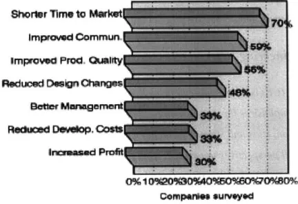
H.S. Abdalla's study (1999) on concurrent engineering for global manufacturing found that CE enables companies to bring products to market at higher quality and less cost. Furthermore, with integrated teams and tools that work and support each other, designers and manufacturing engineers were able to cope with late changes in the product design. Additional benefits (as shown in Figure 5) include shorter time to market, better communication and management, fewer number of design changes, and reduced life-cycle costs in testing and reliability.
Shorter
Imp
Setdl
GomperWes survoye
Figure 5. Benefits gained from implementing concurrent engineering in 150 companies.
2.3 DFMA
Design for Manufacturability and Assembly (DFMA) is one concurrent
engineering technique that attempts to optimize the product design early in the concept design phase and ensure that the product can be manufactured consistently and
cost-effectively. Using a systematic approach to analyze the limitations of manufacturing and assembly at an early stage, DFMA attempts to identify and eliminate possible production issues that may arise during product fabrication. By focusing on how different aspects of the manufacturing process can be monitored and adjusted, DFMA can help companies control costs and manage its production process to deliver robust and consistent products.
When a company can deliver high-quality products, it can achieve additional cost savings can be realized with fewer warrantee repairs and services.
DFMA provides a framework for manufacturing engineers to follow as the product is designed. Common DFMA directives include considerations for the following:
1. Simplify the design and reduce the number of parts 2. Standardize and use common parts and materials 3. Design for ease of fabrication
4. Design within process capabilities and avoid unneeded surface finish requirements.
5. Mistake-proof product design and assembly 6. Design for parts orientation and handling 7. Minimize flexible parts and interconnections. 8. Design for ease of assembly
9. Design for efficient joining and fastening
DFMA ensures that every part in the product adds value and is easy to assemble. Because each additional part requires an additional assembly step, adding one more component equates to adding an extra opportunity for defect and error. As the number of parts goes up, the probability of a perfect product goes down exponentially and the cost of fabrication goes up. Costs related to purchasing, stocking, inventory, work-in-process, and servicing also go up as the number of parts increase. DFMA encourages the
standardization and usage of common parts and materials in order to facilitate design activities, to minimize the amount of inventory in the system, and to standardize handling and assembly operations.
A real focus on design simplification and standardization began with Henry Ford, whose mass-assembled cars had simpler designs and fewer parts than his competitors. DFMA continues to be utilized by hundreds of domestic and international companies in an effort to cut down manufacturing costs and assembly time. Companies like Allied-Signal, Motorola, Hughes Aircraft, and McDonnell Douglas Corporation have all
established efforts to implement DFM philosophies throughout their product lines. Success stories of using DFM principles are abundant. For example, by using DFMA concepts to design and produce its computer workstation with 3D graphics, Silicon Graphics saved 50% in manufacturing time and $350 000 in tooling costs. [4]
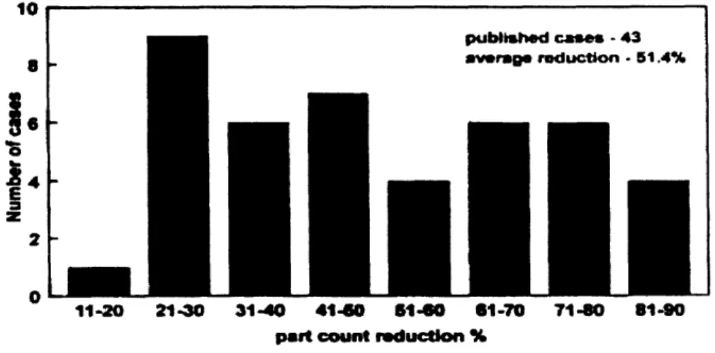
From 1990 -2002, Boothroyd and Dewhurst conducted a study and found that companies who used DFM design principles were able to reduce product part count on average by 51.4%, with some reductions as high as 81-90% (Figure 6). These reductions correlated to an approximate 37% savings in product costs, or annual savings of
$1,417,091. 10
o.
E z 2 A' pubMshed cases - 43 average roduction - 51.4% 11-20 21-30 31-40 41450 614-0 61-70 71-80 81-90 past count reduction %Figure 6. Part count reductions from 43 published case studies where DFMA methods were used since 1990.
2.4 Case Study - Dell Computers
Focusing on design for velocity, assembly, quality, manufacturing, service, total cost, logistics, safety and ergonomics, integration, environment, and modularity, or Design for X, Dell saved an estimated $15 million dollars in direct labor costs by redesigning its Optiframe chassis for PCs. The Design for X (DFX) team consisted of members from procurement, manufacturing engineering, manufacturing quality, customer service, process engineering, new product engineering, supplier quality engineering and logistics. By involving a wide range of manufacturing expertise, Dell ensured that
I
-critical manufacturing issues are considered from the beginning of the product development process.
The DFX team concentrated on defining metrics and implementing tools to measure throughput, time and costs. In addition, it promoted concurrent design
evaluation and innovation. First, the DFX team evaluated the functional purposes of each assembly component in a conceptual design by answering the following three DFA questions:
1. Does the part move relative to other parts already assembled?
2. Must the part be of a different material or be isolated from the other parts already assembled?
3. Must the part be separate from other parts for purposes of assembly or disassembly?
After rating each component on its ease of orientation and assembly, estimates of total assembly time and costs were generated as a guides for design goals and metrics. As the design was being developed, an animated model was shared among the team to allow design and process teams to shape the product concurrently. As the design team proposed changes to the chassis and updated the model, the DFA process was repeated. "For example, during virtual prototyping, process engineers identified assembly points that would cause manufacturing bottlenecks, and the design engineers focused on redesigning those areas. In this way, redesign for reduced part count and assembly time also resulted in the greatest time savings on the production line."
The final design for the Optiframe Chassis achieved the following goals:
* Created a design with commonality throughout the Optiplex product line to allow customization.
* Reduced mechanical assembly time by an average of 32%. * Reduced purchased part count by 50%
* Reduced screw-type count by 67% and screw min/max count (a measure of the minimum and maximum number of screws used in the customized computer configurations for each model) by 55%.
* Made product more service and customer friendly by reducing average service time by 44 percent.
These improvements resulted in substantial gains in productivity for Dell. The increased factory throughput and capacity allowed Dell to avoid having to relocate and build new manufacturing facilities. Reducing part count and assembly steps also enabled
an increase in quality. In addition to the $15 million dollars in direct labor cost savings, Dell reaped a predicted $35 million savings in material cost from chassis integration and supply chain optimization. [11]
Dell was able to achieve aggressive design and cost targets by having a formal review process that focused on DFMA issues and promoted concurrent engineering.
2.5 Summary
Successful product development requires concurrent engineering and design for manufacturing, which can only be performed through the collaboration of many
functional departments. Cross-functional teams are used to make sure that manufacturing concerns are addressed early in the design process. In this approach, the once sequential
activities and tasks are done in a concurrent manner. The cost savings of CE and DFMA are undeniable. The SUGV team must adopt these principles to meet its own cost and quality goals.
3 DFMA Analysis and Results
The DOD's product specifications for the SUGV govern the robot's size, weight, speed, mean-time-to-failure (MTTF), functional temperature range, shock absorbance, etc. A finished SUGV must be a high-quality product that works properly when the
soldiers in the field need it to. Since every specification must be met, there are no tradeoffs between functionalities and costs. Although other factors such as ease of use, maintainability, and aesthetics play a role in developing the SUGV, the main priority of the SUGV team is to deliver a robot that meets all product specifications at the lowest cost possible.
While the design team's goal is to design the SUGV properly to meet all
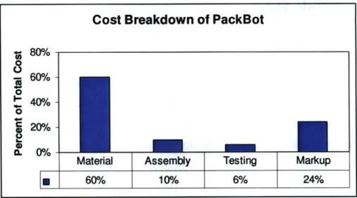
functionality requirements, the manufacturing team's goal is to reduce production costs without compromising quality. Because cost plays a crucial role in product development, I began my analysis by trying to understand the major cost drivers of the SUGV. Since SUGV production had not yet begun at the time of the study, I gathered information from the Packbot production group. (Figure 7)
In accordance with iRobot's Manufacturing Service Agreement (MSA) with its contract manufacturer, iRobot pays a total purchase price based on material costs, assembly labor costs, testing and inspection costs, and final markup for each individual Packbot that comes off of the assembly line.
Materials on a Packbot account for a majority (60%) of the product cost. According to the iRobot sourcing manager, it is common for materials to account for 80% of the total product cost in complex mechanical products. With materials making up a majority of the cost in a product such as the SUGV, iRobot's procurement team
intermittently visits vendors of big ticket items to renegotiate the costs down. However, because iRobot's volumes are low and materials are mostly single-sourced, getting competitive prices can be challenging. A DFMA review of the SUGV provides an alternative solution to reduce material cost by focusing on simplifying the design, reducing part count, and using more cost-effective manufacturing processes.
Cost Breakdown of PackBot
S809i
-
tM0 -/o40%
-n. 0%/o
Material Assembly Testing Markup
60%
10%/o
6%
24%
Figure 7. Cost Breakdown for Packbot
A DFMA analysis can help simplify the design and reduce part count and achieve significant cost savings in materials. Furthermore, if iRobot can optimize its SUGV assembly process, it can realize cost savings in labor. A better assembly process will also result in a higher-quality product, which can reduce testing, inspection, and rework costs. Together, the SUGV team can realize cost savings on material, assembly, testing, and
markup.
To begin understanding how the SUGV is put together, I created the assembly flow charts (Appendix 1) to document the assembly sequence. This visual tool provides a way to note difficulties and inconsistencies in assembling the product. Next, using liaison diagrams and datum flow chain analysis, I examined the structure of the SUGV and identified the key characteristics. With the results of the Boothroyd Dewhurst DFA software, I presented ideas for design changes as well as data on cost savings. Together, this DFMA analysis helped understand how the product functions in order to provide recommendations for simplifying and improving the design.
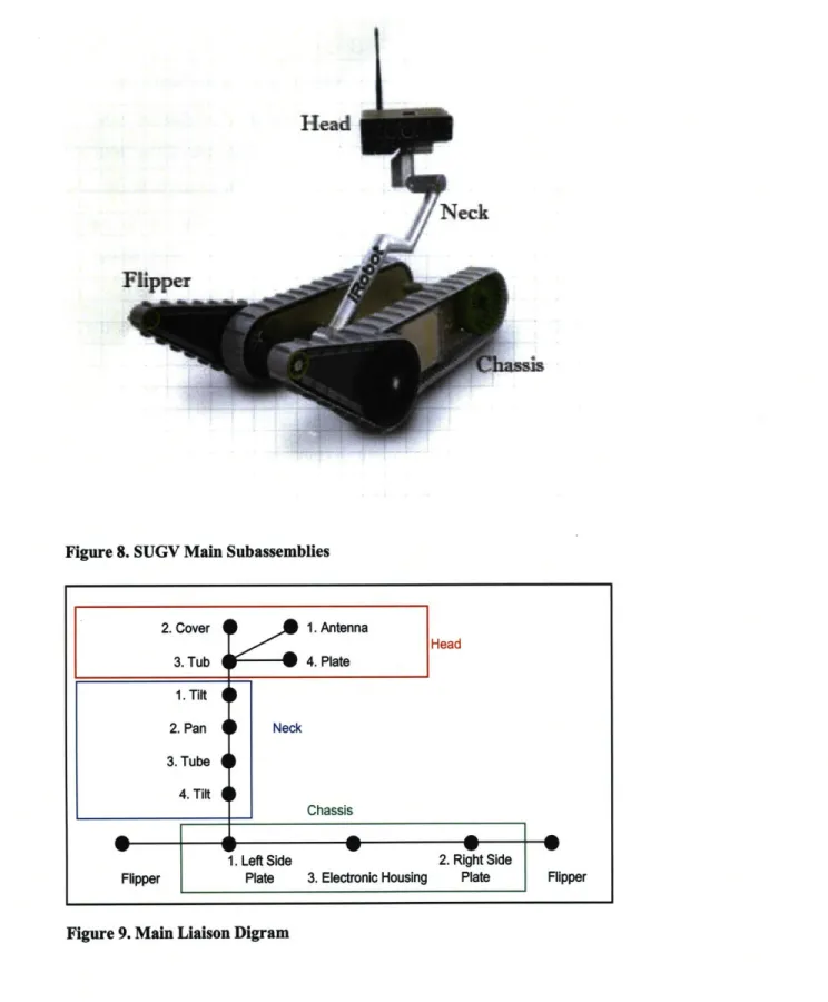
3.1 Structure of SUGV
On a high-level, there are 4 main subassemblies on a SUGV - the head, neck, chassis, and flippers. Figure 8 shows the following features that are apparent in the
first-.... ... ... . ... . .. ... ..
level architecture of the SUGV. The main liaison diagram in Figure 9 depicts how these parts of the SUGV are assembled together.
Head
r__-/I ICA
Figure 8. SUGV Main Subassemblies
2. Cover 3. Tub w Flipper Neck 1. Antenna 4. Plate Head
4
4Plt 1. Tilt 2. Pan 3. Tube 4. Tilt Chassis w w-2. Right Side Plate 1. Left Side Plate FFigure 9. Main Liaison Digram
III Nook=
IiiiiiiiiWOM
;;::;:
---
-
---. I I I I r
W
3. Electronic Housing
FlipperFlipper
To gain a better understanding of the mechanics of how power is delivered to the tracks so that the SUGV can move and maneuver, this analysis will first focus on the chassis. As shown in the more detailed liaison diagram of the chassis (Figure 10), the batteries (6) deliver power to the electronics board stack (5) through PCB boards attached to the left side plate (1) and right side plate (2). Attached to the electronics board stack are the track drive actuators (9). Energy is transferred when the rotation of the teeth on the track drive actuators (9) make contact with the teeth found on the inside of the front wheel hubs (11). The rotation of the track drive actuators (9) drives the rotation in the front wheel hubs, which in turn drives the attached front wheels (8). Finally, one rubber track (17) on each side of the chassis mates with the front wheel (8) and the back wheel (18) so that when the front wheels turn, the track propels both wheels synchronously. Although not depicted in the drawing for clarity, the back wheels (18) are located by the rear wheel hubs, which are again constrained by the left and right side plates.
The other important mechanical function shown in the liaison diagram is the control of the flippers, which enables the SUGV to climb stairs and maneuver through rugged terrain. Similar to the track wheels, the batteries (6) deliver power to the
electronics board stack (5) through PCB boards attached to the left side plate (1) and right side plate (2). The flipper actuator (7) is connected to the electronics stack board on one end, and the pick off gear (14) on the other end. Since the pick off gear (14) constrains rotational movement along the y-axis' on the torque tube (12), the torque tube spins when the flipper actuator (7) moves and transfers energy to the pick off gear (14). The flippers
(10) are located and constrained by the torque tube, which can be controlled by keeping track of the angular position of the torque tube. This is done through the use of the signal processing chip by measuring the position of a magnet that sits on top of the absolute position sensor gear (13).
1 In the reference plane shown below, the SUGV is defined to reside on the XYplane, facing the positive X
3. Belly Pan and
Rear Stiffener
Gear 12. Torque Tube Gear
Figure 10. Chassis Liaison Diagram
3.2 Key Characteristics
After looking at the physical relationships among all the parts, I analyzed how these parts work together to achieve its intended function, or how key characteristics2 are delivered. In order to fulfill its functional requirements of mobility (speed and stair-climbing), the SUGV must ensure the delivery of power from the batteries to the wheels and flippers. The key characteristics that ensure the SUGV's ability to perform these functions are the following:
2 Key characteristics are the product, subassembly, part, and process features whose variation from nominal significantly impacts the performance of the product. [16]
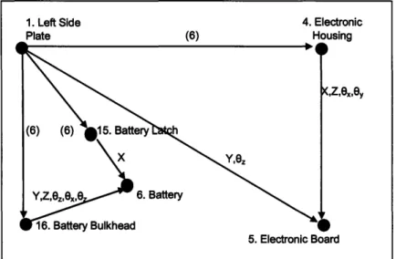
Key Characteristic 1: Battery connection to the side plate PCB boards. The battery,
which needs to be easily replaceable, must be properly attached to the battery bulkhead in order to deliver power to the electronics through the side plate PCB boards. The battery latch is an adjustable mechanism that helps lock the battery in place. From the datum flow chain (DFC), we see that the features are properly constrained - if the battery latch can securely hold the battery in the x-direction. The distance between the latch and the bulkhead, or the clearance of the battery between these two features, is a key
characteristic that can affect the delivery of power.
Figure 11. Battery to PCB Datum Flow Chain
Key Characteristic 2: Power delivery to front wheels.
The delivery of power from the track drive actuator to front wheel is a key characteristic that drives the SUGV. The important features include the location of the actuators on the electronics board relative to the side plates as well as the distance between the teeth of the drive wheel actuator to the front wheel hub. The datum flow chain (DFC) in Figure 12 shows how this feature is properly constrained. The front wheel is held in place in the y-direction by the retaining ring. All other degrees of freedom for the front wheel (8) are constrained by the front wheel hub (11). The front wheel hub (11) is held in place in the y-direction by the retaining ring (19), in the x and z-directions by the torque tube (12). The torque tube (12) also constrains the front wheel hub's (11) angular motion in the x
1. Left Side 4. Electronic
Plate (6) Housing
and z-direction. The rotational motion in the y-direction is controlled by the track drive actuator (9), which is held in all six degrees of freedom by the electronic stack board (5).
The electronic stack board (5) is in turn restricted in motion by the electronic housing (4) and the side plates (2). Since all of the features involved in delivering power to the front wheels, redesign efforts should be focused elsewhere.
4. Electronic Housing 4
X,Z,6x,Ey
5. Electronic Stack Board 19. Retaining Ring (6) 9. Track Drive Actuators 8.Front Wheel X,Z, x,Oy,,z X,Z,E 10. Flipper 10. Flipper
Y,e8
2. Side Plate6)
7 Flipper Actuator
Y,ez p11. Front Wheel Hub
X,Z,exe6z
x,,,ez
(6)
12. Torque Tube
14. Torque Tube
Pick off Gear
Figure 12. Datum Flow Chain for Power Delivery to Actuators
Key Characteristic 3: Delivery of power from the flipper actuator to flippers.
The delivery of power from the flipper actuator to the flippers is another key
characteristic that allows it to maneuver through rougher terrains and climb stairs. The datum flow chain (DFC) in Figure 12 shows how this key characteristic is properly
constrained. The rotational motion of the flippers (10) in the y-axis, along with the other five degrees of freedom, is controlled by the torque tube (12). The torque tube is in turn located in all six degrees of freedom by the torque tube pick off gear (14), which is held
by the right side plate (2) and the flipper actuator (7). The features delivering this key
characteristic are all properly constrained.
m w • i 1
E
P
Key Characteristic 4-1: The distance between the absolute position sensor gear and the torque tube.
Key Characteristic 4-2: The clearance of the absolute position sensor gear on the left side plate.
The sensor gear has a locating feature that aligns with the torque tube to allow the sensor processor chip to properly measure the angular position of the torque tube (and the
flippers). The sensor gear must be aligned properly and fit over the torque tube tightly enough so that the locating feature does not slip away. At the same time, the gear must fit inside the machined hole of the left side plate and have enough clearance to rotate. Otherwise, the torque tube and flippers cannot be controlled. Even if the sensor gear can be installed at the time of assembly, special software tests should be conducted to ensure that the locating features can accurately measure and control the angular movement of the flippers.
Key Characteristic 5-1: Clearance of flipper axle from the torque tube. Key Characteristic 5-2: Clearance of torque tube from front wheel hub.
The flipper axle has five retractable hooks that lock the axle into five corresponding holes in the torque tube when inserted. The interlocking of the pawls and torque tube creates the force that moves the flippers when the actuator rotates. The use of fewer than five pawls did not create enough strength to move the flipper with the torque tube. A push button on the outside of the flipper allows for easy disassembly of the flipper from the chassis. When the pawls make a connection to the torque tube, the clearance between the flipper axle and the torque tube must be small enough to force the flipper to rotate with the torque tube and big enough to allow for easy insertion and removal. Furthermore, in order for the flippers to rotate, the torque tube must also have enough clearance to rotate inside the front wheel hub. A new design using fewer pawls would save on assembly time.
Key Characteristic 6: The drive track's tolerance with respect to the front and back wheels.
Each track on the SUGV is made up of three pieces that are glued together and then stretched to fit around the front and back wheels. The allowable tolerance between the track and the wheels is small. Tracks that are too loose will cause slippage as the front wheels rotate without catching onto the tracks. Although unlikely, it is possible for the slippage to cause the tracks to spin off of the wheels. On the other hand, tracks that are too tight will cause stress on the tracks, leading to a shorter functional life.
Key Characteristic 7-1: Distance of electronic housing edge to both side plates. Key Characteristic 7-2: Distance of gear covers to side plates.
Key Characteristic 7-3: Distance of battery to battery bulkhead.
To satisfy the functional requirement of maneuvering through low levels of water, the SUGV uses o-rings in between the side plates and the electronic housing to prevent water
leakage into the electronics. For an o-ring to form a protective seal, the two joining parts must apply the right amount of pressure on the o-ring. To ensure that the o-rings form a waterproof seal, additional screws were added and vacuum tests must be performed. Redesign of this part could lead to reduction in assembly time or testing.
Key Characteristic 8: The distance between the left and right side plates.
The liaison diagram (Figure 10) shows that our left and right side plates are
over-constrained in the y-direction by the belly pan, rear stiffener, and electronic housing. All three of these features play a role in setting the distance between the side plates. Failure can arise due to variation in the differences of distances because water can seep into the electronics housing if not enough pressure is put on the o-ring that resides in between the side plate and the housing. To ensure proper fit, the design under study uses 20 screws that hold each side plate to the electronics housing, 10 screws to hold the belly pan to the side plates, and 2 heavy duty 6x25mm screws to secure the rear stiffener. As a solution for this over-constrained feature, the team recommended the molding or casting the chassis in a single piece. This would resolve the problems of multiple features defining the distance between the side plates and eliminate the 32 screws mentioned above.
Key Characteristic 9-1: Clearance of electronics board stack in housing. Key Characteristic 9-2: Clearance of torque tube inside front wheel hubs and electronics housing.
As part of the chassis assembly, the electronics board stack, along with the LCD and actuators attached, must slide into the housing (Figure 13). Later in the assembly sequence, the torque tube must be inserted through the same electronics housing among the cables and actuators of the electronics board stack. Assemblers must be careful that the insertion of the torque tube does not hit any wires or knock off any features from the electronics board. There must be enough clearance for the board and torque tube to slide in. Also, the torque tube must be able to freely rotate inside the front wheel hubs and
electronics housing without interference. Additionally, the electronics housing must be able to correctly locate the board in relations to the side plates so that the actuators can be screwed on from the outside of the side plate. Redesign of this feature would eliminate the possibility of breaking the electronics board and lead to fewer assembly problems.
Figure 13. Electronics Assembly into Housing
3.3 DFA Software
To systematically study the design and assembly procedures of the SUGV, I used the Boothroyd Dewhurst's DFA software. The DFA software provides a quantifiable way to estimate assembly time and cost contribution of each part of the product. At the end of the analysis, the software provides a list of components that should be examined
for the possibility of combining with another part or elimination. In addition to providing
information on the difficulty of assembly based on ease of handling, orientation, insertion, etc, the DFA software provides data that helps in decision making.
3.3.1 Inputs
Before inputting information about the different items in the assembly, I had to first determine the total number of SUGVs that will be produced. Since iRobot expects to build approximately 80 SUGVs per month over a full year, I approximated that 1,000 SUGVs will be built over the lifetime. The software spreads out the investment tooling costs over these 1,000 units. Next, I needed to find the hourly wage for assembly workers, and manufacturing plant efficiency. The software uses these two numbers to calculate the cost of labor. As a conservative estimate, I used the hourly rate charged by our current CM for the Packbot and an efficiency of 80%.
!9 h16 XDX t 0'1 a 1A I I u M ,l ? Ma wor useuY 9 ma to* Pl r-ute ! -1, mJt~ i141 na W WW plow. srew T ot 141 . 9.17 22,22 Fe rewbnftm of tm8UtU Caset 1 21 L~ We , 2s.30 25.61 Lpb cost, L 0.16 1.66 w op.osdtL 0.00 0.00 MPAtW= 3.6 -
S-
-s --1 rn w-ow** ' g At '& seledthe Owr bmtar ftr
R
ilSSpa. B aw sem I s base pantW. Is
hwA pars
t*eew 4viiw *r"s Ceer"
ftmjis I a tmwwtdt
ft Con co A
Iw21 emme do"
i•nehwIIgand tS 24.00 Ic r''pw9* _ k b~ Iy
L'Tooe
*IIhI•
2
a
.
w i, -,
20.3
WVtper fatmog 1'85
- t-1
Figure 14. Boothroyd and Dewhurst DFA Software
1; ----
~-- ; ;
---ý08- "t Q-OW k lo tim1l-W WOute
::: : ~ :::;';I; ';--::---I~~
After the general information is inputted, the software records each item in the product in the order that it is assembled. The DFA software collects the following information on each separate item (Figure 14).
Definition
Under the definition tab, a user specifies the part name, part number, count, and item type of each individual item in the SUGV. The part name is used in the summary assembly tab in the leftmost column for easy recognition. The part number is used to account for the same components used in different areas of the assembly. The repeat
count allows users to specify multiple identical items such as screws in the assembly
sequence without having to input each part separately. Finally, the user must specify the
item type of the component - part or subassembly. Every "part" is associated to a unique cost required to obtain the part. Multiple parts make up a subassembly, whose cost is
associated to the sum of the costs of its underlying parts.
Minimum part criteria
Under the minimum part criteria tab, a user must specify the purpose of the
individual items by classifying the item as a theoretically necessary part, or a part that is a candidate for elimination. The Boothroyd and Dewhurst method believes that the only parts that are theoretically required are the items that:
1. have to move relative to the rest of the assembly. 2. must be made of a different material.
3. must be separate for reasons of assembly or repair. 4. act as a base part (one per product)
The minimum part count is the sum of the number of all parts that fall into one of these four categories. Any other item not included in this group is considered to be a candidate for elimination. If we define a well-designed product to be one that needs all the parts it has, a well-designed product typically has three times the number of parts as predicted by the minimum part count.
Envelope dimensions
In the envelope dimensions tab, a user chooses shape of the item - cylindrical or rectangular. A cylindrical item has diameter and height input variables while a
rectangular item has length, width, and height variables. If an item is extremely small (or extremely big), the software believes that the item will be difficult to handle and
assemble. Thus, the software includes extra time for assembling this item.
Labor Time
The labor time tab calculates the amount of time needed to handle, fetch, and insert the item. The software assigns a time for fetching each item based on our
assumption that all items are "within easy reach". The software also calculates an insertion/operation time for each item based on the size, shape, symmetry, handling difficulties, insertion difficulties, and securing method. Multiplying the sum of these two times by the efficiency rate and hourly labor wage provides the estimated cost of
assembling a particular item.
Symmetry
Users must specify the symmetries of an item because parts that are symmetrical are easier to align and more difficult to be inserted incorrectly.
Handling difficulties
Under the handling difficulties tab, a user can identify items that are difficult to handle if 100 units of this item were placed in a big box. For examples, the item might be flexible, easy to tangle, heavy, or too small to handle. The software adds additional handling/insertion time in calculating assembling time.
Insertion difficulties
The insertion difficulties tab provides options for the software to factor in the extra time required to insert difficult items. For example, threading a screw into a hole that is obstructed in view or access would take an extra long time.
Securing method
Under the securing method tab, a user chooses how the item is secured to the assembly. The software uses industry data to estimate the time required to perform the securing operation. If the item is threaded, there are options to choose the number of revolutions required and the method used (hand screwed vs. screwdriver vs. electric screwdriver).
Manufacturing data
The user can also specify the cost, tooling investment, weight, material, and manufacturing process of the item. Since the sum of all the parts is displayed under the product column on the right, the cost and weight contribution of any single item can be quickly and easily determined.
Notes
The user can take additional notes under the Notes tab.
Picture
For clarity, the user has the option to upload a CAD image of each part into the
DFA software. The picture is simply a visual image that has no impact on the analysis.
It is not necessary to complete the engineering drawings in order to use the software.
Visit Tracking
The tracking variable under this tab helps the user note the status of the items in the software - not visited, partially visited, or fully visited. The software provides a
viewing option that enables the user to view items based on its individual status, which is convenient for quickly sorting out items with incomplete information.
Assembly
As a user fills in the information for each mechanical part for the SUGV, the leftmost column of the software becomes populated to display a list of all the components that make up the product. This list can be configured to display or hide specific
components based on the type of component or tracking status. This tab is where a user can enumerate additional operations such as reorientation of the assembly, application of glue, and the wiring of cables to provide even more accurate details on the assembly sequence. The DFA software provides time estimates for these operations.
Results
When all of the fields are completed, the DFA questions proposed by the software are answered. The Results Tab on the bottom left column compiles all of the information on cost, weight, minimum part count, etc to show how each part contributes to overall assembly time and cost. Furthermore, the software makes it convenient for a user to copy and paste a design, make modifications to the existing model, as well as compare and contrast the results of the different designs. By copying the original model and changing specific items and subassemblies, I was able to quickly determine the cost savings of each specific design change.
3.3.2 Outputs
Our analysis shows that 1,306 mechanical parts make up the SUGV. According to the assumptions of the DFA software, the only parts that are absolutely necessary are a base component, items that require a different material property, items required for movement, and items that cannot be attached until other parts have been assembled. Based on this assumption, 317 items of the total 1,306 make up the theoretical minimum part count on a SUGV.
The SUGV's DFA index3, a measure of the assembly efficiency, is 14.1%. Because the DFA index of a well-designed product should be around 30%, the SUGV
DFA index tells us that the SUGV contains more parts than a well-designed product
would have. With each subsequent design cycle, the ratio can be recalculated and then compared against the original design to see the relative changes in efficiency.
Based on user inputs defined in the Inputs section, the DFA software enumerates items and operations that fit a generic set of guidelines for redesign and provides general recommendations for possible redesign:
* Combine connected items or attempt to rearrange the structure of the product in order to eliminate items whose function is solely to make connections.
* Reduce separate operations where possible. Try to improve or eliminate any which do not add value to the product and yet contribute significantly to assembly time.
* Add assembly features such as chamfers, lips, leads, etc., to make items self-aligning.
* Redesign the assembly where possible to allow adequate access and unrestricted vision for placement or insertion.
* Consider redesign of items to eliminate or reduce handling difficulties for individual assembly items nest/tangle/are difficult to grasp.
* Consider redesign of the individual assembly items to eliminate resistance to insertion or severe insertion difficulties.
The DFA software is a great tool to track all of the items in the product and to summarize the data in a clear format. The SUGV has 345 fasteners, with 54 different varieties. The software calculates how much faster the product can be assembled if one
3 Ratio of the theoretical minimum assembly time to an estimate of the actual assembly time for the product calculated by:
DFA Index - (Theoretical Minimum # Parts)x(3 Seconds)
Estimated Total Assembly Time Since 0 < DFA Index < 1, higher score indicates easier to assemble products.


![Figure 4. The over-the- design method [Ullmduan]. Mawall](https://thumb-eu.123doks.com/thumbv2/123doknet/14682710.559617/22.918.150.764.857.996/figure-design-method-ullmduan-mawall.webp)