Advances in MRI to Probe the Functional and Structural
Network of the Macaque Brain
by
Mark Haig Khachaturian
B.S.E. Nuclear Engineering & Engineering Physics (2001) University of Michigan, Ann Arbor, MI
S.M. Nuclear Engineering (2003)
Massachusetts Institute of Technology, Cambridge, MA
Submitted to the Department of Nuclear Science and Engineering in partial fulfillment of the requirements for the degree of
DOCTOR OF PHILOSOPHY IN NUCLEAR SCIENCE AND ENGINEERING AT THE
MASSACHUSETTS INSTITUTE OF TECHNOLOGY September 2007
© MIT 2007. All rights reserved
The author hereby grants to MIT permission to reproduce and to distribute publicly this paper and electronic copies of this thesis document inw orni
Signature of Author:
7 77',
Def;artment of K#cle'ar Science and Engineering
"- July 30 h, 2007 Certified by:
Bruce Rosen Professor of Radiology, Harvard Thesis Committee Chairman Certified by:_
Ce.i.d.y .. Wim Vanduffel, Thesis Supervisor
Assistant Professor in Radiology, Harvard Certified by: _
David Tuch, Thesis Supervisor
2
>7
Head of Medical Physics, Novartis Pharma AG
Certified by:
Alan Jasanoff, Thesis Reader .rofessorLof Nuclear Science and Engineering, MIT Certified by:
David Cory, Thesis Reader -' ' Professor of Nuclear Science and Engineering, MIT
Accepted by:
- Jetffery Coderre, Thesis Reader
Chairman of the Department of the Committee of Graduate Students
ARCHAU
MASSACHUSETTS INSTrIT OF TECHNOLOGYJUL 24
2008
LIBRARIES
IAdvances in MRI to Probe the Functional and Structural
Network of the Macaque Brain
by
Mark Haig Khachaturian
Submitted to the Department of Nuclear Science and Engineering on July 30,th 2007
in partial fulfillment of the requirements for the degree of Doctor of Philosophy in Nuclear Science and Engineering
at the
Massachusetts Institute of Technology
Abstract
Diffusion MRI and fMRI have provided neuroscientists with non-invasive tools to probe the functional and structural network of the brain. Diffusion MRI is a neuroimaging technique capable of measuring the diffusion of water in neural tissue. It can reveal histological architecture irresolvable by conventional magnetic resonance imaging methods and has emerged as a powerful tool to investigate a wide range of neuropathologies. fMRI is a neuroimaging technique sensitive to hemodynamics which is indirectly linked to neural activity. Despite the applications of diffusion MRI and fMRI in basic and clinical neuroscience, the underlying biophysical mechanisms of cerebral diffusion and the hemodynamic response remain largely unknown. Also, these neurotechnqiues suffer from low SNR compared to conventional MRI. The challenges associated with the acquisition and interpretation of diffusion MRI and fMRI limit the application of these powerful non-invasive neuroimaging tools to study the functional and structural network of the brain.
The purpose of this thesis is three fold; (1) improve the acquisition and reconstruction of the diffusion MRI and fMRI signals and (2) develop an MR-compatible cortical cooling system to reversibly deactivate cerebral glucose metabolism, and (3) apply the cortical cooling system to investigate the effect of cerebral glucose metabolism on cerebral diffusion and the hemodynamic response. First, I describe a novel phased array monkey coil capable of improving the resolution of diffusion MRI (4 fold increase) and fMRI (2 fold increase) in monkeys. Secondly, I present a novel reconstruction method to resolve complex white matter architecture which boosts the sampling efficiency of the diffusion MRI acquisition by 274-377%. Thirdly, I present a MR-compatible cortical cooling system capable of reversibly deactivating cerebral metabolism in monkeys. The cortical cooling system has been applied to study the effect of cerebral glucose metabolism on the cerebral diffusion of water. I use MR temperature maps to quantify the region and degree of deactivation (accuracy of +1 TC in vivo). Then, I show that reversible deactivation of cerebral glucose metabolism affects the magnitude of cerebral diffusion (12-20%) but not the anisotropy. Finally, I apply the cortical cooling system to study the effect of reversibly deactivating cerebral glucose metabolism in V1 and its effect on the hemodynamic response in the visual system. Reversible deactivation of V1 decreased the hemodynamic response in visually driven regions upstream and downstream from Vl. Compensatory effects were observed in VI in both hemispheres and ipsilateral TEO with in 2 minutes of deactivation. Here I have described the tools to probe the functional and structural network of the macaque brain.
Thesis Supervisor: Wim Vanduffel
Title: Assistant Professor of Radiology, Harvard Thesis Supervisor: David Tuch
Acknowledgements & Support
First and foremost, I would like to thank Professor Wim Vanduffel and Dr. David Tuch for funding my research. I deeply appreciate the five years they spent training me in neuroimaging and neuroscience. I would also like to thank Professor Bruce Rosen for providing me with the opportunity to work at the Athinoula A. Martinos Center and Professors Alan Jasanoff, David Cory, and Jeffery Coderre for providing me with valuable input on my research. Furthermore, I would like to thank Professors Sidney Yip and Sow-Hsin Chen for their advice on topics ranging from particle physics to career planning. My nights in the laboratory would have been less productive without Helen Deng, John Arsenault, and Leeland Ekstrom. In addition, I received invaluable support from Larry Wald, Andreas Potthast, Ken Kwong, Thomas Benner, Leonardo Angelone, David Salat, Kevin Teich, Simon Sigalovsky, Nathanael Hevelone, Timothy Reese, and Josh Synder. I could not have completed this thesis without the love and emotional support of my father, Arek Khachaturian, my mother, JoAnn Diane Khachaturian, my sister, Lee Khachaturian and my girlfriend, Bettina Romberg.
My PhD has been one of the most exciting and enjoyable times in my life. It is in no small part due to the brothers of the AO chapter of AAD. The six years I spent living in the chapter has provided me with memories which I will treasure for the rest of my life. I would like to extend special thanks to Brothers Warren Ruder, Manish Gaudi, Patrick Hereford, David Van Aken, Nelson Sanz, Adan Gutierrez, Stan Bileshi, Matthew Wallace, Mike Szulczewski, and Brothers Eric Sparks and Martin Lee of the Penninsular Chapter of AA(D.
I would like to thank the following grants and institutions for supporting my research: IUAP 5/04, EF/05/014, FWO G151.04, HFSPO RGY0014/2002-C, GSKE, NINDS NS46532, NINDS MH67529, NCRR RR14075, NIBIB EB005149, NCI CA09502, NCI 5T32CA09502, the Athinoula A. Martinos Foundation, the MIND Institute, the National Alliance for Medical Image Computing (U54 EB05149) which is funded by the NIH Roadmap for Medical Research, the Human Frontiers Science Program (RGY 14/2002), and Deutsche Forschungsgemeinschaft (GRK320 and KO 1560/6-2).
Table of Contents
List of Figures ... 7 List of Tables ... 11 §1 Introduction ... 12 1.1 Introduction... 12 1.2 Purpose ... 13 1.3 Outline ... 15§2 Phased Array Coil Developm ent ... 17
2.1 Introduction... 17
2.2 Background ... 17
2.3 M aterials and M ethods ... 18
2.3.1 10 cm Transm it/Receive Coil ... 18
2.3.2 10 cm Transm it-Only Coil... 19
2.3.3 4-Channel Receive Coil... 19
2.3.4 Pream plifiers ... 20
2.3.5 Anim al Preparation ... 20
2.3.6 Data Acquisition ... 21
2.3.7 TI Anatom ical Im ages... 23
2.4 Results ... 23 2.4.1 Coil Properties... 23 2.4.2 SNR ... 24 2.4.3 g-factor ... 25 2.4.4 fM RI ... 26 2.4.5 Diffusion M RI ... 28 2.5 Discussion ... 28 2.6 Conclusion ... 29
§3 Diffusion M RI Reconstruction M ethods ... 30
3.1 The Diffusion MRI Signal is Proportional to the Average Self Propagator ... 30
3.2 Reconstruction M ethods ... 30
3.2.1 Diffusion Tensor Im aging (DTI) ... 30
3.2.2 Q-space Im aging (QSI)... 33
3.2.3 Q-ball Im aging (QBI) ... 33
3.2.4 Technical Lim itations ... 34
§4 Q-ball Imaging Using Multiple Wavevector Fusion36 ... ... . . . .... 35
4.1 Introduction... 35
4.2 Theory ... 36
4.2.1 Q-ball Im aging... 36
4.2.2 M ultiple W avevector Fusion ... 36
4.2.3 Spherical W avelet Basis ... 37
4.2.4 Intravoxel Peak Connectivity M etric (IPCM ) ... 38
4.3 M ethods ... 39
4.3.1 Num erical Sim ulation... 39
4.3.2 Hum an Data Acquisition ... 40
4.3.3 M W F Fusion... 42
4.4 Results ... 43
4.4.1 N um erical Sim ulation... 43
4.4.2 Hum an Data... 45
4.5 Discussion ... 49
4.6 Conclusion ... 50
§5 Design of a MRI-Compatible Cortical Cooling System2 ... ... . . . .... 51
5.1 Introduction... 51
5.2 Background... 51
5.3 Design Specifications... 52
5.4 Cryoprobe ... 53
5.5 Pum p System ... 54
5.6 Cooling System Properties... 55
5.7 Conclusions and Future W ork... 56
§6 Reversible Deactivation of Cerebral Glucose Metabolism Affects the Diffusion MRI Signals1 57 6.1 Introduction... 57
6.2 Background ... 59
6.3 M ethods ... 61
6.3.1 Anim als... 61
6.3.2 RD Cooling System ... 61
6.3.3 Experim ental Design ... 62
6.3.4 Im age Registration and V isualization... 64
6.3.5 Statistical Analysis... 64
6.4 Results ... 65
6.4.1 Accuracy and Precision of the MR Temperature Maps: Ex Vivo Experiment... 66
6.4.2 Block D esign: In V ivo Experim ent ... 67
6.4.3 AD C Decrease During Cortical Deactivation... 68
6.4.4 N onparam etric Perm utation Testing (NPPT) ... 70
6.4.5 ROI Analysis ... 72
6.5 D iscussion... 76
6.6 Conclusion ... 79
§7 Reversible Deactivation of V1 During Awake Monkey fMRI... 80
7.1 Introduction... 80
7.2 Background ... 81
7.3 M aterials and M ethods... 82
7.3.1 Anim al Preparation ... 82
7.3.2 RD Cooling System ... 82
7.3.3 Reversible Deactivation... 83
7.3.4 Functional M RI A cquisition ... 83
7.3.5 Therm ocouple M easurem ents... 83
7.3.6 Anatom ical M RI Acquisition ... 84
7.3.7 M R-defined Tem perature M aps... 84
7.3.8 Statistical Analysis... 85
7.3.9 Activity Profiles... 85
7.3.10 V isualization... 85
7.4 Results ... 86
7.4.1 Deactivation Region ... 86
7.4.2 BOLD fMRI Response in the Warm and Cold Conditions ... 87
7.5 Discussion ... 90
7.6 Conclusion ... 92
§8 Conclusions ... 93
8.1 Summ ary ... 93
8.2 Future W ork ... 93
8.2.1 Reversible Deactivation fM RI Studies ... 93
8.2.2 Functional Pathway M apping ... 94
8.2.3 Resolving White Matter Architecture in Neurodegenerative Diseases ... 94
References ... 95
Appendix ... 104
A .N otation ... 104
List of Figures
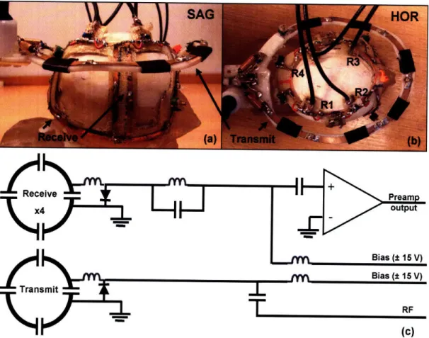
Figure 2-1. (a) Sagital and (b) horization orientations of the 4-channel phased array receive coil (R1 -R4) and 10 cm transmit coil on the monkey model. (c) Circuit schematic of the transmit and receive coils. ... 2 0 Figure 2-2. SNR of (a) single and (b) phased array functional EPI at 1.25 mm isotropic resolution with
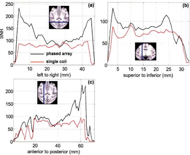
identical sequence parameters. Both images are on the same scale... 24 Figure 2-3. SNR of (a) left-right, (b) anterior-posterior, and (c) superior-inferior projections of the
phased array and single coil for functional EPI at 1.25 mm isotropic resolution. The SNR of the phased
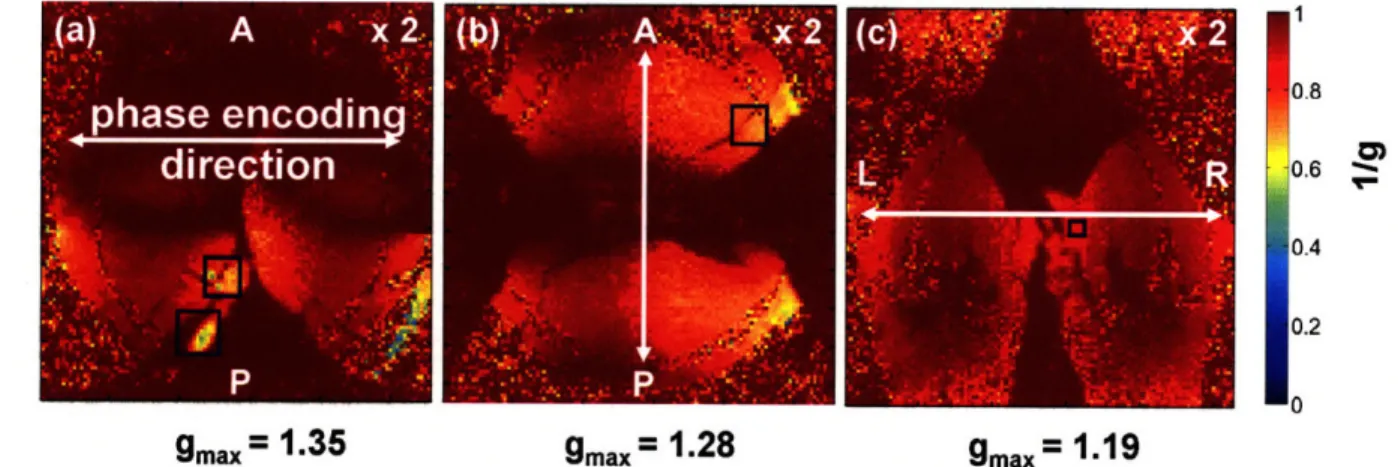
array coil is always greater than or equal to that of the single coil... 25 Figure 2-4. 1/g-factor maps for the (a) right horizontal, (b) anterior-posterior horizontal, and (c)
left-right coronal phase encode directions for two-fold GRAPPA acceleration, R = 2. The blue boxes indicate where the maximum g-factor in the slice is located. In 85% of the brain, the SNR decrease is less than
15% for two-fold GRAPPA acceleration. The average SNR decrease in the brain is - 50% for R = 3 (data
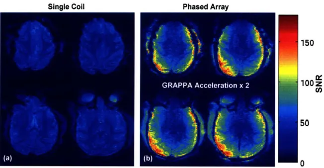
not show n) ... 26 Figure 2-5. SNR of (a) single and (b) phased array functional EPI at 1 mm isotropic resolution. The
phased array coil images where taken with a GRAPPA acceleration factor of 2. Note, the improvement in the image quality on the around the edge of the brain in the phased array image. Both images are on the
sam e scale ... 27
Figure 2-6. Functional EPI (with MION) acquired with the phased array coil for (a) Ml, (b) M2, and (c) M3 at 1.0 mm isotropic resolution, TE/TR = 24/2700 ms. Ml has a larger brain than M2 and M3 resulting in lower SNR in the middle of the brain. However the SNR in all monkeys is sufficient ( -25)
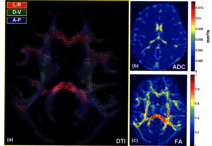
to measure the MION response in visually driven cortex ... 27 Figure 2-7. (a) DTI, (b) ADC, and (c) FA maps acquired with the phased array coil at 0.9 mm isotropic
resolution in Ml. The phased array coil resolves the ADC and FA throughout the brain... 28 Figure 3-1. (Left) TI image of monkey. (Right) Diffusion tensors calculated from a 0.9 mm isotropic DTI acquisition. The colors of the rectangloids indicates their direction; red = left-right, blue =
anterior-posterior, green = superior-inferior... ... 31 Figure 3-2. (Left) ADC and (Right) FA maps calculated from a DTI acquisition at 0.9 mm isotropic on a
monkey. The FA, which is a measure of anisotropy, is highest in white matter... 32
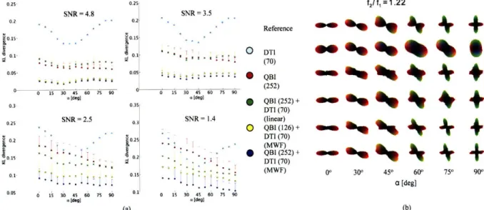
Figure 4-1. Schematic diagram of MWF fusion algorithm ... 37 Figure 4-2. (a) Reconstruction accuracy of diffusion ODF reconstruction methods (Table 4-2) for a
synthetic 2-Gaussian system with fl=0.45 and f2=0.55 for four SNR values. KL (±SEM) divergence between reference ODF and estimated ODF as a function of separation angle ca between the principal eigenvector of the Gaussian compartments. (b) ODFs from randomly selected, individual noise trials from
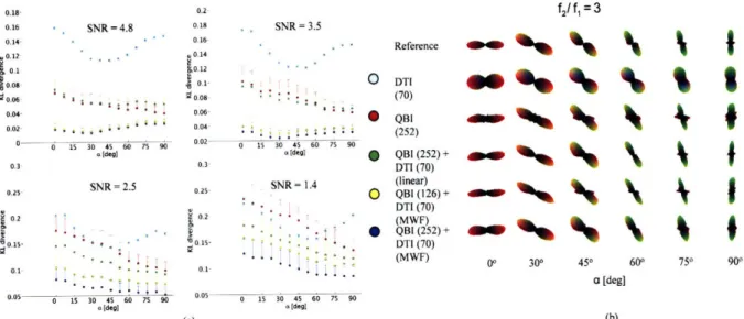
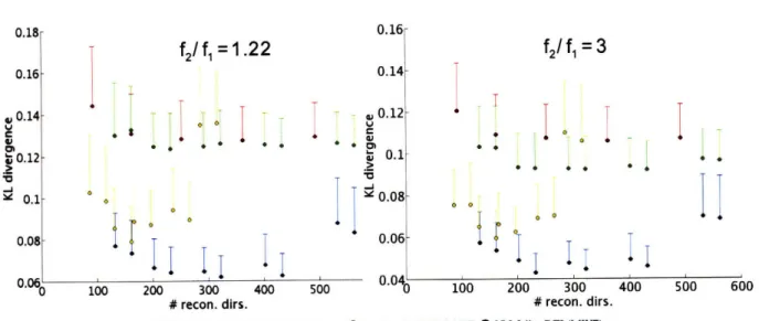
(a) w ith SN R = 2.5... 43 Figure 4-3. (a) Reconstruction accuracy of diffusion ODF reconstruction methods (Table 4-2) for a
between reference ODF and estimated ODF as a function of separation angle a between the principal eigenvector of the Gaussian compartments. (b) ODFs from randomly selected, individual noise trials from (a) w ith SN R = 2.5... 44 Figure 4-4. Reconstruction accuracy of the DTI, QBI, and the MWF technique as a function of total
sampling directions for (left)f1 = 0.55 andf 2 = 0.45 and (right)f1 = 0.25 andf2 = 0.75. The subsampling
was done by taking only the top hemisphere of directions (z > 0) for a given sampling scheme ... 45 Figure 4-5. Diffusion images of crossing between optic radiation and arcuate fasciculus. (a) DTI, (b) QBI, (c) MWF of DTI and full QBI, (d) MWF of DTI and hemisphere QBI. Note that the crossing peaks (arrow) are more clearly defined on (d) than on (b). af, arcuate fasciculus; Cun, cuneus; MTG, middle temporal gyrus; OR, optic radiation. The ODFs that the arrows point to in (b,c, and d) are magnified in the in sets ... 46 Figure 4-6. Intersection between posterior cingulum bundle and splenium. (a) DTI, (b) QBI, (c) MWF of DTI and full QBI, (d) MWF of DTI and hemisphere QBI. The crossing peaks (arrow) are discernible on the MWF images (c,d) but not the standard QBI (b). pCB, posterior cingulum bundle; sCC, splenium of corpus callosum. The ODFs that the arrows point to in (b,c, and d) are magnified in the insets ... 47 Figure 4-7. (a) IPCM calculated for 252 dir. QBI in six slices of a participant (I). (b) IPCM calculated for 196 dir. MWF in the same six slices as (a). All images are on the same scale... 48 Figure 4-8. (a) IPCM calculated for 122 dir. QBI in across six participants (II-VII). (b) IPCM calculated for 196 dir. MWF in the same slices as (a). All images are on the same scale ... 48 Figure 5-1. (a) Coolant probe used and attached thermocouples. (b) Schematic (not to scale) of coolant probe orientation on the dura above Vl 1. The radial symmetry of the probe ensured that it was in the same position for each experim ent ... 54 Figure 5-2. Recording well used in cortical cooling experiments. The recording well was glued to the skull using dental acrylic... 54 Figure 5-3. Schem atic of cooling system ... 54 Figure 5-4. Thermocouple readings on the cortical surface during a cooling profile for three trials. The thermocouple measurements illustrate the consistency of the cooling profile... 55 Figure 6-1. Schema 72. The heterogeneity of flow velocities can give rise to apparent diffusion... 60
Figure 6-2. (a) MR-defined temperature map during cooling of ex vivo bovine muscle (5.5 min. after start of cooling). The location of the probe is indicated by the black circle and the location of the thermocouple under the probe by the circle with an 'x' inside. (b) Plot of MR thermometry measurements (average of 4 voxels) versus thermocouple readings during the cooling and recovery stages of the experiment. Both images shows the change in temperature from the ambient (22 oC)... 67 Figure 6-3. Epoch-averaged ADC (top row) and FA maps (bottom row) for the warm, cold, and recovery conditions for an experiment where the temperature under the probe = 8 oC (cortical deactivation #1, M 1). The change in ADC is apparent under the probe (white rectangle) during the cold condition, however, no change in the FA is visible ... 69 Figure 6-4. ADC maps during warm, cold, and recovery conditions for an experiment with the temperature under the probe, Tc = 21.5 TC as measured by MR thermometry (Ml). Only in experiments
where there was a significant amount of tissue below the metabolic cutoff of 20 TC were changes in the AD C observed during cooling... 69 Figure 6-5. (a) Region where ADC changed significantly (p < 0.05) between the warm and recovery conditions versus the cold condition as calculated by NPPT (cortical deactivation #1, MI). (b) Isothermals at 34, 30, 20, 15, 10 TC overlaid on the region with significant ADC changes as shown in (a). Note that the statistically significant region extends far beyond the cooled region and is present where the temperature has not changed significantly from the body temperature (T > 34 OC isothermal)... 71 Figure 6-6. (a) Regions where ADC changed significantly (p < 0.05) between the (warm + recovery conditions) versus the cold condition as calculated by the NPPT (cortical deactivation #1, M2). (b) Isothermals at 34, 30, 20, 15, 10 oC overlaid on the region with significant ADC changes as shown in (a). Note that the statistically significant region extends beyond the cooled region and is present where the temperature has not changed significantly from the body temperature (T > 34 oC isothermal)... 72
Figure 6-7. ROI analysis of ADC changes (± SEM) during the warm, cold and recovery epochs in Ml. Data are plotted for all voxels which showed a significant change in ADC but that did not change in temperature (T > 34 oC) during the cold condition. Panels a and b show data of gray and white-matter voxels respectively. Two control regions where also included. The 1t control region (cROI 1) was
chosen to measure the variation of ADC in a region far from cooling (see anatomical inset). The 2nd
control region (cROI 2) is closer to the probe as ROI 1 but shows no change in ADC. This indicates that the change in ADC is not a function of temperature, nor of distance from the probe... 73 Figure 6-8. ROI analysis of ADC changes (± SEM) during the warm, cold and recovery epochs in M2. Sam e conventions as in Figure 6-7... 74 Figure 6-9. (Left) Plot of the mean normalized ADC (± SEM) in Ml for gray matter and white matter voxels in the three temperature ranges: T > 34 TC (ROI 1), 20-34 TC (ROI 2), 8-20 TC (ROI 3). Red, blue, and green values indicate the normalized ADC during the warm, cold, and recovery conditions respectively. (Right) Plot of the mean normalized ADC (± SEM) in M2... 75 Figure 6-10. The in vivo ADC (ADCin ivo, red) and the ADC of free water (ADCfree water, red) plotted as a
function of temperature from the nine reversible deactivation experiments. The deactivation region, T < 20 oC, from Ml and M2 was used to define an ROI to compare the ADC between the nine reversible deactivation experiments. Note the ADCin viv follows the diffusion of free water for T > 20 oC, but not
below the m etabolic cutoff... 76 Figure 7-1. Thermocouple data from 10 reversible deactivation fMRI scans during Experiment 2. The cooling profile was 1 min warm - 2.5 min cold - 3.5 min warm - 3 min cold - 2 min warm. The consistency of the cooling profile is illustrated over Exp. 2-10. The first deactivation (Exp. 1, blue line) is warmer than subsequent deactivations because it is always more difficult to cool the brain in the first deactivation cycle... 84 Figure 7-2. MR-temperature maps (T < 20 oC) overlayed on the inflated (inset) and ipsilateral hem isphere flat m ap... 86 Figure 7-3. BOLD fMRI activity, Itl > 3 during calculated by comparing the visual stimuli epoch versus the fixation epoch for the (left) warm, W, and, (right) cold, C, conditions (Experiment 2). The deactivation region is enclosed by the dotted blue line. The hemodynamic response in the seven regions (brown dots) was compared in the ipsilateral and contralateral hemispheres (Figure 7-4, Figure 7-5)... 87
Figure 7-4. BOLD fMRI activity compared in deactivated V 1 (DV 1), neighboring VI (NV1), peripheral VI1 (PV1), PV2, PV3, PV4, LGN, and TEO in the (a) ipsilateral and (b) contralateral hemispheres during Experiment 1. Neighboring VI was not visually driven during the warm condition but visually driven during the cold condition. The effects of reversible deactivation are seen in both hemispheres ... 88 Figure 7-5. BOLD fMRI activity compared in deactivated V I (DV 1), neighboring VI (NV1), peripheral VI (PV1), LGN, and TEO in the (a) ipsilateral and (b) contralateral hemispheres during Experiment 2. Same conventions as Figure 7-4. There was a larger hemodynamic response across the brain during Experiment 2. However, the same general trends in the hemodynamic response during the warm and cold conditions are seen in Experim ents 1 and 2 ... 89 Figure 7-6. t-score maps, representing a positive and negative correlation with the metabolism of the deactivated region. (a) Inflated ipsilateral hemisphere, (b) functional maps, and (c) flat map of ipsilateral hemisphere,. The maps where thresholded for
Itj
> 3. Positive and negative correlations are seen in both hemispheres in visually and non-visually driven regions. In (b) the location of the probe is denoted by the yellow rectangles ... 90List of Tables
Table 2-1. Relative SNR (+ SEM) in the phased array coil relative to the single coil in primary visual cortex (VI), the frontal eye fields (FEF), and the lateral geniculate nucleus (LGN) in the left and right hemispheres (LH, RH). Values in parenthesis represent significant p-values from a two sample t-test comparing the SNR in the single and phased array coils (a = 0.01)... 25 Table 4-1. Summary of the M W F algorithm ... 37 Table 4-2. Acquisitions and reconstructions used in numerical simulations... 40 Table 4-3. Difference of the mean IPCM between the MWF and QBI reconstructions for seven subjects in w hite m atter ... 47 Table 5-1. Advantages and disadvantages of using cortical cooling and drug injection... 52 Table 5-2. Description of the cortical cooling system components... 55 Table 6-1. Percent change in ADC relative to the first warm ADC value for three temperature ranges (> 34 oC, 20-34 OC, < 20 oC) during the warm, cold, and recovery conditions (± SEM). The values in the parenthesis are statistically significant p-values (alpha level = 0.001) from a one sample t-test... 71
§1 Introduction
1.1 Introduction
One of the goals of neuroimaging research is to measure the various aspects of neural function and quantify how they depend on external stimuli and how they change during neurodegenerative diseases. To this end, diffusion MRI and fMRI have provided neuroscientists with non-invasive tools to probe the functional and structural network of the brain.
Diffusion MRI is a neuroimaging technique capable of measuring the diffusion of water in neural tissue. Diffusion MRI is sensitive to the diffusion of water on length scales ranging from 10 nm to 100 pm, and over time scales ranging from 1 ms to 1 s. Given that the average size of neurons in the brain is about 10 pm, diffusion MRI provides a sensitive probe of tissue microstructure. It can reveal aspects of histological architecture irresolvable by conventional magnetic resonance imaging methods.
Diffusion MRI has emerged as a powerful tool to investigate neuropathologies such as stroke, Parkinson's disease, HIV dementia, schizophrenia, cocaine addiction, normal aging, Alzheimer's disease, chronic alcoholism, multiple sclerosis, epilepsy, and ALS. More recently, diffusion MRI has also been proposed as a promising technique to identify anatomical white-matter fiber tracts in vivo and measure neural activity. Despite the applications of diffusion MRI in basic and clinical neuroscience, the underlying biophysical mechanisms that affect cerebral diffusion contrast remain largely unknown.
Since its development in the early nineties, functional magnetic resonance imaging (fMRI) has been very useful in helping neuroscientists map the brain (i.e. localizing brain regions involved in the processing of particular functions). fMRI is sensitive to hemodynamics which is correlated to some degree with neural activity. fMRI studies have explored the hemodynamics associated with sensory processing, motor, and cognitive skills and have focused mainly on 'mapping' questions. Combining fMRI with other techniques (reversible deactivation, electrophysiology, etc.) could provide more information on the underlying mechanisms of the hemodynamic response and could be used to measure the interactions between functional regions.
Also, owing to the low SNR of the diffusion MRI and fMRI signals, it is difficult to acquire images in a time efficient manner. The challenges associated with the acquisition and
interpretation of diffusion MRI and fMRI limit the application of these powerful non-invasive neuroimaging tools to study the functional and structure network of the brain.
1.2 Purpose
The goal of this thesis is to develop tools to further the application of diffusion MRI and fMRI to study the functional and structural network in the macaque brain. I accomplish this goal by (1) improving the acquisition and reconstruction of the diffusion MRI and fMRI signals and (2) developing an MR-compatible cortical cooling system to reversibly deactivate cerebral glucose metabolism, and (3) applying the cortical cooling system to investigate the effect of cerebral glucose metabolism on cerebral diffusion and the hemodynamic response. The following five Specific Aims were proposed:
Specific Aim 1: PURPOSE: HYPOTHESIS: RESULTS: ORIGINAL CONTRIBUTIONS: FUTURE APPLICATIONS: Specific Aim 2: PURPOSE:
Develop a 4-channel 3T phased array monkey coil
To develop a 4-channel 3T phased array coil for diffusion MRI and fMRI studies in awake and anesthetized monkeys.
Test the hypothesis that the 4 channel 3T phased array coil will have higher SNR and less EPI distortions across the brain compared to a single channel transmit/receive coil.
The SNR of the 4-channel 3T coil was always greater than or equal to the SNR of a single transmit/receive coil. The phased array coil improved the resolution of fMRI and studies by a factor of 2 and the resolution of diffusion MRI studies by a factor of 4.
I describe a novel phased array monkey coil capable of improving the resolution of fMRI and diffusion MRI while accommodating variations in monkey head size.
To apply the general methodology to develop phased array coils with more than four coil elements and at higher magnetic fields.
Develop and optimize the multi-wavevector fusion of DTI and QBI data to resolve white matter architecture
To develop a general framework to improve the sensitivity and angular contrast of the orientation distribution function (ODF) calculated from high angular resolution diffusion imaging (HARDI) methods, specifically Q-ball imaging (QBI).
HYPOTHESIS: RESULTS: ORIGINAL CONTRIBUTIONS: FUTURE APPLICATIONS: Specific Aim 3: PURPOSE: HYPOTHESIS: RESULTS: ORIGINAL CONTRIBUTIONS: FUTURE APPLICATIONS: Specific Aim 4: PURPOSE:
Test the hypothesis that the multi-wavevector fusion (MWF) of DTI and QBI improves the stability and angular contrast of the ODF reconstruction using numerical simulation and human results.
The MWF of DTI and QBI resulted in a sampling efficiency boost of 274-377% while resolving more white matter architecture than QBI alone.
I present a novel reconstruction method to resolve white matter architecture which boosts the sampling efficiency of current diffusion MRI reconstruction methods.
To apply the MWF of DTI and QBI to study the changes in white matter architecture in neurodegenerative diseases.
Develop and validate cortical cooling system using MR temperature maps To develop a MR-compatible cortical cooling system to reduce the cerebral temperature below the metabolic cut-off temperature (20 'C). To acquire MR temperature maps using proton resonance frequency shift thermometry (PRFST) and measure the accuracy and precision of the temperature maps against fiber optic thermocouples in ex vivo tissue.
Test the hypothesis that the cortical cooling system can deactivate cortical tissue and that PRFST is accurate to within ± 1 TC of the fiber optic thermocouples.
An MR-compatible cooling probe was developed. Cortical tissue can be deactivated (T < 20 oC) in one minute. PRFST was accurate to within ± 0.6
oC of the fiber optic thermocouples. The precision of the in vivo PRFST measurements is ± 1 oC at 2.0 mm isotropic resolution.
I present a MR-compatible cortical cooling system capable of reversibly deactivating cerebral glucose metabolism in monkeys. In addition, I use MR temperature maps, with an accuracy of ±1 oC in vivo, to quantify the region
and degree of deactivation. Quantification of the deactivation region has not been possible with any other reversible deactivation method.
To apply the MR-compatible cortical cooling system to the study of the effect of cerebral glucose metabolism on perfusion MRI, MRI spectroscopy, and other imaging modalities (i.e. FDG-PET).
Measure cerebral diffusion properties during the reversible deactivation of cerebral glucose metabolism
To apply the MR-compatible cooling system to quantify the effect of cerebral glucose metabolism on the apparent diffusion coefficient (ADC) and
HYPOTHESIS: RESULTS: ORIGINAL CONTRIBUTIONS: FUTURE APPLICATIONS: Specific Aim 5: PURPOSE: HYPOTHESIS: RESULTS: ORIGINAL CONTRIBUTIONS: FUTURE APPLICATIONS:
fractional anisotropy (FA) as measured by diffusion tensor imaging (DTI). Test the hypothesis that the ADC and FA are affected by cerebral glucose metabolism.
Reversible deactivation of cerebral glucose metabolism resulted in ADC changes (12-20%) in regions where the temperature did not change. No changes in FA were observed. The in vivo ADC as a function of temperature was also measured.
I apply the MR-compatible cortical cooling system to study the underlying mechanisms of diffusion MRI and find that the ADC has a metabolic component.
To study what aspects of cerebral glucose metabolism could account for the decrease in the ADC.
Measure the hemodynamic response in the visual system during reversible deactivation of V1
To apply the cortical cooling system to reversibly deactivate VI and measure its affect on the hemodynamic response of the visual system.
Reversible deactivation of V I modulates the hemodynamic response in visual structures.
Reversible deactivation of VI decreased the hemodynamic response in regions upstream and downstream from V1. Compensatory effects were observed in both hemispheres within 2 minutes of deactivation. Positive and negative correlations between metabolic activity in VI and the MRI signal in visually and non-visually driven structures were also observed.
I apply the MR-compatible cortical cooling system to study the effect of cerebral glucose metabolism in Vl on the hemodynamic response in visual network.
To perform reversible deactivation fMRI experiments to explore the perception of the visual field and the plasticity of the macaque brain. Also, FDG-PET experiments can be performed to determine if visually and non-visually driven structures require input from VI to remain metabolically active.
1.3 Outline
This thesis is divided into 7 sections (§2-8). §2, describes the development and construction of a 4-channel 3T phased array coil used for acquiring diffusion MRI and fMRI
(Specific Aim 1). §3 reviews the theory behind the diffusion MRI reconstruction methods. Then, I present a novel diffusion MRI reconstruction method for resolving white matter architecture with diffusion MRI in a more sampling efficient and accurate manner (Specific Aim 2) than previous methods (§4).
Again, I sought to quantify the effect of cerebral glucose metabolism on cerebral diffusion and the hemodynamic response (Specific Aims 3-5). §5 describes the development of a MR-compatible cortical cooling system capable of reversibly deactivating cerebral glucose metabolism (Specific Aim 3). §6 describes the application of the cortical cooling system to study the effect of cerebral glucose metabolism on cerebral diffusion (Specific Aim 4). In §7, the cortical cooling system was applied to study the effect of reversibly deactivating cerebral glucose metabolism in VI on the hemodynamic response in the visual system (Specific Aim 5).
The thesis concludes with §8, which summarizes the major contributions of my research and future research projects.
§2 Phased Array Coil Development
2.1 Introduction
Awake monkey fMRI combined with conventional neuroscience techniques (e.g. electrophysiology, lesion studies, reversible deactivation, optical imaging, etc.) has the potential to study the hemodynamic response to external stimuli and the interactions between regions of the functional network-1 5. The majority of monkey MRI experiments are performed with single coils1'4'5. Though previous monkey studies have provided valuable information, single coil full
brain fMRI and diffusion MRI studies suffer from severe EPI distortions at resolutions higher than 1.25 mm isotropic for fMRI1'4'5 and 1.5 mm isotropic for diffusion MRI6.
By constructing phased array coils for monkey MRI studies, substantial gains in SNR and image quality could be achieved using parallel imaging7
-1
0. The major challenge associated withconstructing phased array coils for monkeys is the variation in head size. Phased array
technology is based on placing the multiple receive channels as close to the head as possible11. Therefore, the natural variation in monkey head size makes rigid coils impractical. A more minor concern is the space constraints associated with awake monkey fMRI experiments. The monkeys is confined in a chair with its headpost secured to the outside of the chair4. This leaves very little room for RF coils and renders birdcage designs useless.
Here, we describe a 4-channel phased array coil capable of improving the resolution and image quality of full brain awake monkey fMRI and diffusion MRI experiments. The novel aspect of the phased array coil is that can adapt to different rhesus monkey head sizes (ages 4-8). The methodology described in this section can be used in the development of phased array coils for other primates and small animals with more than four coil elements and at higher magnetic fields.
2.2 Background
The most popular fast image acquisition scheme used in diffusion MRI and fMRI studies is called echo planar imaging (EPI). EPI suffers from susceptibility distortions at the boundary between regions with differing magnetic susceptibilities. The distortions can be so severe that registration with anatomical MRI images is not possible leaving the results difficult to interpret.
It is necessary to increase the resolution of EPI in order to further neuroscience applications. Also, improving the resolution may provide new applications of MRI.
The technique of parallel imaging emerged in the late 1990's as a means to decrease the distortions in EPI imaging 9,10. The theory of parallel imaging allows one to reduce number of
lines sampled in k-space, thus reducing the accumulation of phase errors due to susceptibility distortions. Parallel imaging accomplishes this by using the coil sensitivity functions of multiple radio-frequency (RF) receive coils (termed phased array). Parallel imaging is capable of producing relatively distortion free EPI images without increasing the scan time and with little loss in SNR. Parallel imaging allows neuroscientists and clinicians alike to achieve higher resolution and make use of the advances in MR hardware.
Diffusion MRI and fMRI studies on monkeys can provide valuable information unattainable in humans. However, little effort has been put towards developing a robust full brain phased array coil capable of parallel imaging for awake and anesthetized monkey studies. Therefore, diffusion MRI and fMRI studies on monkeys have been limited in resolution by EPI distortions and SNR.
2.3 Materials and Methods
2.3.1 10 cm Transmit/Receive Coil
Most full brain awake monkey fMRI experiments have been performed with a single transmit/receive coil3-5,12. A single transmit receive coil has the advantage of being easy to setup and is not affected by variations in size of monkeys heads. In order to quantify the benefits of the 4-channel phased array receive coil, we designed a 10 cm transmit/receive coil.
A 10 cm transmit/receive coil was made from flexible circuit board material (Dupont Pyralux, Durham, NC) and glued (Gougeon Corp. - G5 Adhesive Hardener and Resin Epoxy, Bay City, MI) to a thermoplastic base. The coil was formed in the shape of a 'saddle' to improve the uniformity of the field compared to a circular coil while not affecting the vision of the monkey. The conductor width was 4 mm. The coil had seven capacitors on it and one variable capacitor (Voltronics, Denville, NJ). The coil plugged into a single preamplifier (Advanced Receiver, Burlington, CT). The orientation of the transmit coil (both for the single coil and phased array) is shown in Figure 2-la,b. The physical shape of the single transmit/receive coil and transmit-only coil was the same.
2.3.2 10 cm Transmit-Only Coil
It would be ideal to use the body transmit coil of the MRI scanner in conjunction with all phased array coils because of its uniform magnetic field over the object. However, the duration and magnitude of RF pulses necessary to reach high resolution (< 1.0 mm isotropic) in animal experiments can induce spiking in the preamplifiers. However, with a custom build 10 cm transmit-only coil, the field of the transmitter is not large enough to reach the preamplifiers. Thus, functional and diffusion MRI experiments are only limited in resolution by the coil properties and not other hardware considerations.
The transmit-only coil was constructed in the same manner as the 10 cm transmit/receive coil. However, a detuning circuit was added so the transmit coil did not interfere with the phased array receive coil during image acquisition. A orientation of the transmit coil relative to the phased array coil is shown along with a schematic of its circuitry in Figure 2-1.
2.3.3 4-Channel Receive Coil
A model of a monkey's head was made from T1 anatomical images using 3D stereolithagraphy (Medical Modeling, Golden, CO). The monkey model is shown in Figure 2-la,b. A monkey helmet was made from fiberglass cloth (Bondo, Atlanta, GA) and shaped to the monkey model. Four layers of fiberglass cloth were glued together using epoxy to give the monkey helmet a combination of strength and flexibility. The four receive coils were made from flexible circuit board material (Dupont Pyralux, Durham, NC) and glued to the monkey helmet (Gougeon Corp. -G5 Adhesive Hardener and Resin Epoxy, Bay City, MI). A standard capacitive bridge match and PIN diode (MA4P4002B-402; Macom, Lowell, MA) trap was used to detune the receive coils13. Two coils were overlapped on the left side of the helmet and two coils were overlapped on the right side. The coupling, S12, between the overlapping coils was checked (< -20 dB) before gluing the coil to the monkey helmet. The coupling between second nearest neighbor coils was minimized using preamplifier decoupling (see next section). Figure 2-la,b shows a picture of the phased array coil from the sagital and horizontal views on the monkey model and Figure 2-1 c shows a schematic of the phased array coil circuitry.
Bias (+ 15 V)
Transmit
T
RF
(C)
Figure 2-1. (a) Sagital and (b) horization orientations of the 4-channel phased array receive coil (R1 - R4) and 10 cm transmit coil on the monkey model. (c) Circuit schematic of the transmit and receive coils.
2.3.4 Preamplifiers
A preamplifier board was constructed and made portable to accommodate the different stereotactic apparatus and monkey chairs used in awake and anesthetized MRI experiments. The preamplifier board consists of eight preamplifiers (Siemens Medical Solutions, Erlangen, Germany), and four bias lines (+ 30 V) to tune and detune the transmit and receive coils. Preamplifier decoupling was employed using a cable trap with semi rigid coax (Suhner UT-070 type) to suppress any residual coil coupling from next nearest neighbor interactions11'14. The
preamplifier circuitry is shown in Figure 2-1 c. 2.3.5 Animal Preparation
MRI data were acquired from three juvenile male rhesus monkeys (macaca mulattas, M1,
5.5 kg, ID #3704, M2, 4.9 kg, ID #0404, M3, 5.7 kg, ID #4505). The data were acquired on a
Siemens Trio 3T MRI scanner located at the Athinoula A. Martinos Center for Biomedical
Receive
X
x4
f MI
Imaging, Massachusetts General Hospital (Charlestown, Massachusetts). All procedures conformed to Massachusetts General Hospital, Massachusetts Institute of Technology, and the National Institutes of Health guidelines for the care and use of laboratory animals (Subcommittee on Research Animal Care protocol #2003N000338).
Ml was placed into a magnet compatible stereotactic apparatus (Kopf Instruments, Tujunga, California) for an anaesthetized experiment to compare the performance of the single coil to the phased array coil. Anaesthesia was maintained using ketamine and xylazine (induction 10 and 0.5 mg/kg, i.m., maintenance with ketamine only). Local anesthetic (lidocaine cream) was applied to the ends of the ear bars and ophthalmic ointment was applied to the eyelids to minimize discomfort induced by the stereotactic apparatus. A heating pad was placed beneath the monkey to keep it warm during the scan session.
The monkeys were placed in a monkey chair (Crist Instruments, Washington, DC) during awake experiments. All monkeys were implanted with a headpost (Crist Instruments, Washington, DC) that was secured to the monkey chair using two M5 peek plastic screws. Also a rail system was used to slide the monkey chair in the magnet to minimize motion. The following sequences were used to quantify the behavior of the phased array coil and single coil.
2.3.6 Data Acquisition 2.3.6.1 g-factor Maps
Proton density gradient-echo images were acquired in order to calculate g-factor maps of the phased array coil for horizontal, coronal, and sagital slices as described in Wiggins et al 11. Raw k-space data was obtained with TR/TE/flip = 200 ms/4.14 ms/200, 1.5 mm single slice, 128
x 112, and 100 x 87 mm FOV.
2.3.6.2 Coil sensitivity maps
Proton density gradient-echo images were also acquired in order to perform a non-uniform signal normalization on the Tl anatomical images to improve gray and white matter contrast and aid in image registration (50 slices, TR/TE/flip = 1190 ms/3.72 ms/80, 1.0 mm
2.3.6.3 fMRI
Functional single shot echo planar images (EPI) were acquired at two different resolutions (1.25 mm, 1.0 mm isotropic) to compare the SNR and image quality of the single coil to the phased array coil. The SNR properties of the coils was compared on a voxel-wise basis using the following equation for SNR;
SNR= S (2.1)
6background
where S is the signal in a voxel and Obackground is the standard deviation of the background.
fMRI-
1.25 mmForty horizontal slices were acquired using TE/TR = 26/2980 ms, 72 x 64 matrix, 900 flip angle at 1.25 mm isotropic resolution. The same sequence was used for the both the single coil and phase array coil.
fMRI-
1.0 mm BOLDFifty horizontal slices were acquired using TE/TR = 26/3290 ms (phased array coil), 26/5000 ms (single coil), 96 x 84 matrix, 900 flip angle at 1.0 mm isotropic resolution. The phased array coil had a lower TR because parallel imaging9'1
0,15 was employed, specifically
generalized auto-calibrating partially parallel acquisitions (GRAPPA, R = 2).
fMRI - 1.0 mm MION
Microcrystalline iron oxide nanoparticles, (MION)26'2 7, enhanced fMRI data was
collected on all monkeys. Fifty horizontal slices were acquired using TE/TR = 24/2700 ms, 96 x 84 matrix, 900 flip angle at 1.0 mm isotropic resolution using the phased array coil. The Siemens AC88 gradient insert was used (BW = 1305 Hz/voxel) to decrease the TR. GRAPPA with an acceleration factor of two was employed5.
2.3.6.4 Diffusion MRI
The diffusion preparation used a twice-refocused spin echo 16. Fifty-seven horizontal
a matrix size of 96 x 96. The sequence parameters were TE/TR = 93/10100 ms, b = 700 s mm-2. The diffusion gradient sampling scheme consisted of n = 60 directions which were obtained using the electrostatic shell method 17. Ten images with no diffusion weighting were also
obtained for a total of 70 acquisitions. The total acquisition time was 11 min 48 sec. The diffusion images from five acquisitions were averaged and reconstructed using the diffusion tensor model'.
2.3.7 T1 Anatomical Images
T1 anatomical images were acquired with an MPRAGE sequence19 with TR/TI/TE = 1910/1100/3.06 ms, a = 80, 0.65 mm isotropic resolution, total acquisition time: 6 min 35 sec. The functional EPI, proton density and GRE images were registered to the TI images for comparison between the single and phase array coils.
2.3.8 Image registration and visualization
Images were registered using the flirt command (rigid registration, 6 degrees of freedom) in the FSL toolbox (http://www.fmrib.ox.ac.uk). All visualization post-processing was performed using custom software written in Matlab (version 6.5.1.199709 (R13) Service Pack 1). DTI reconstructions were visualized with custom software written in C++ and VTK (version 4.2) (http://public.kitware.com/VTK). The tensors were visualized as color-coded rectangloids.
2.4 Results
2.4.1 Coil Properties
The coupling between the coils was measured using the S12 measurement on a network
analyzer. The two sets of overlapping coils had < -20 dB decoupling between them. Next nearest neighbor coupling was < -10 dB. In addition, the preamp decoupling added -20 dB of decoupling. Therefore, all coils had < -30 dB of decoupling between them ensuring each coil behaved as a single element in the tuned state. PIN diode detuning achieved > 35 dB isolation between the tuned and detuned states. The unloaded/loaded Q-factors of the individual coils was
2.4.2 SNR
The SNR for all images was calculated using Eq. (2.1). The SNR in four slices of Ml for the single and phased array coils is shown in Figure 2-2. The identical sequence was used for both coils and both images are on the same scale. Note the SNR benefit of the phased array coil is along the edge of the brain closest to the coils. In the center of the brain, the SNR is nearly the same for both coils.
Single Coil Phased Array
250 200 150 z Cn 100 50
pnaseu array iuncuonal zri at 1.13 mm
isotropic resolution with identical sequence parameters. Both images are on the same scale.
Figure 2-3 presents the SNR profile along the different axes of the brain. Table 2-1 presents the relative SNR of the phased array coil to the single coil in regions relevant to fMRI studies.
z
C,)
S1U 20 30 40 5 10 15 20 25 30
left to right (mm) superior to inferior (mm)
20 40 60
anterior to posterior (mm)
Figure 2-3. SNR of (a) left-right, (b) anterior-posterior, and (c) superior-inferior projections of the phased array and single coil for functional EPI at 1.25 mm isotropic resolution. The SNR of the phased array coil is always greater than or equal to that of the single coil.
Table 2-1. Relative SNR (± SEM) in the phased array coil relative to the single coil in primary visual cortex (VI), the frontal eye fields (FEF), and the lateral geniculate nucleus (LGN) in the left and right hemispheres (LH, RH). Values in parenthesis represent significant p-values from a two sample t-test comparing the SNR in the single and phased array coils (a = 0.01). Region SNRPA/SNRsc LH RH V1 2.5 + 0.07 (6e' 9) 1.8 ± 0.07 (3e-') FEF 1.5 + 0.04 (3e5) 2.2 + 0.1 (2e5) LGN 0.99 ± 0.06 1.1 + 0.08 2.4.3 g-factor
An important property of a phased array coil is its g-factor map. The inverse g-factor map quantifies how much SNR is lost in the brain during a parallel acquisition compared to an
image with no acceleration, R = 1. The parallel imaging capabilities of a 4 channel coil limit the acceleration factor to two, (i.e. R = 2)9. Figure 2-4 presents the inverse g-factor maps for the
phased array coil for an acceleration factor of two in the different phase encode directions. Less than 15% of the SNR is lost during an acceleration factor of two in 85% of the brain. The maximum g-factor of 1.35 (Figure 2-4a) occurs in the horizontal slice with left-right phase encoding.
-U
1
0.8 0.6 " 0.4 0.2 Agmax = 1.35 gmax = 1.28 gmax= 1.19
Figure 2-4. 1/g-factor maps for the (a) left-right horizontal, (b) anterior-posterior horizontal, and (c) left-right coronal phase encode directions for two-fold GRAPPA acceleration, R = 2. The blue boxes indicate where the maximum g-factor in the slice is located. In 85% of the brain, the SNR decrease is less than 15% for two-fold GRAPPA acceleration. The average SNR decrease in the brain is - 50% for R = 3 (data not shown).
2.4.4 fMRI
Functional EPI (BOLD) was acquired at 1.0 mm isotropic resolution. The TR of the phased array coil was much shorter (3290 ms) compared to that of the single coil (5000 ms) because parallel imaging (GRAPPA, R = 2) was employed. Figure 2-5 presents EPI at 1.0 mm isotropic for the single and phased array coil. The benefit of parallel imaging with regards to EPI distortions is apparent around the edge of the brain along with the benefit in SNR.
1
Phased Array 150 100z so n• 50 0 Id
Figure 2-5. SNR of (a) single and (b) phased array functional EPI at 1 mm isotropic resolution. The phased array coil images where taken with a GRAPPA acceleration factor of 2. Note, the improvement in the image quality on the around the edge of the brain in the phased array image. Both images are on the same scale.
Figure 2-6 presents functional EPI (MION) of Ml, M2, and M3. The images were acquired with the AC88 gradient insert (Siemens, Erlangen, Germany). The SNR profiles in the brain are relatively consistent between the monkeys despite the natural variation in head size. Ml has the largest head and thus the signal in the middle of the brain is the lowest compared to M2 and M3.
M1
M2
M3
60
40 z
co20
Figure 2-6. Functional EPI (with MION) acquired with the phased array coil for (a) M1, (b) M2, and (c) M3 at 1.0 mm isotropic resolution, TE/TR = 24/2700 mins. Ml has a larger brain than M2 and M3 resulting in lower SNR in the middle of the brain. However the SNR in all monkeys is sufficient ( - 25) to measure the MION response in visually driven cortex.
2.4.5 Diffusion MRI
Figure 2-7 depicts the DTI reconstruction of a 0.9 mm isotropic acquisition in Ml. The tensor map is overlayed on a Tl with a rigid registration algorithm. ADC and FA maps calculated from the tensors are presented in panels b and c. The phased array coil resolves the ADC and FA throughout the brain.
0.012 0.01 0.008 E 0.006 E 0.004 0.002 A
Figure 2-7. (a) DTI, (b) ADC, and (c) FA maps acquired with the phased array coil at 0.9 mm isotropic resolution in Ml. The phased array coil resolves the ADC and FA throughout the brain.
2.5 Discussion
The SNR benefit of the phased array coil compared to the single coil throughout visual cortex, make it ideal for awake monkey fMRI studies (Figure 2-2, Figure 2-3, and Table 2-1). In addition the benefit of using the phased array coil with parallel imaging improves the resolution of awake monkey fMRI experiments at 3T by a factor of 2 (Figure 2-5 and Figure 2-7) and diffusion MRI experiments by a factor of 4 (Figure 2-7). Parallel imaging also improves the
time efficiency of fMRI studies by 35% due to a lower TR. The preservation of the anatomical integrity of the diffusion images implies registration with T1 images is possible with a rigid registration algorithm. Thus, tensor maps can be visualized on a TI image making tractography more accurate. During parallel imaging, an SNR loss of less than 15% is present over 85% of the brain with a maximum loss of 26%, GRAPPA = 2 (Figure 2-4). The coil does not interfere with the eyes of the monkey, or with the headpost of the monkey because all of the coils are on the side of the head (Figure 2-1). This allows eye tracking to be performed during fMRI experiments. In addition, the flexibility of the fiberglass helmet allows the coil to easily adapt to different monkeys (Figure 2-6).
Though four coils were used in this phased array, future phased arrays with more coils could be constructed using the same techniques described in this section. The general methodology of making a monkey helmet from a mold based on TI anatomical images, can be applied to primates and other animals. More importantly, the practical application of the coil should be taken into account when developing a phased array coil. For example, for fMRI studies only interested in retinotopy, it may be more suitable to use more channels regardless of the coils performance in deep cortical structures20 . Also, for T1 anatomical studies of rhesus monkeys, a headpost is not necessary. This would allow one to put coils on top of the brain making the phased array coil superior to the single coil throughout the brain.
2.6 Conclusion
A 3 Tesla 4-channel phased array coil was developed to improve the resolution and image quality of awake monkey fMRI and diffusion MRI experiments. The phased array coil had a SNR benefit of - 2 on surface cortex and was equal to that of a single coil in the center of
the brain. The phased array coil allowed parallel imaging to be employed reducing EPI distortions. It improved the resolution of fMRI studies by a factor of 2 while increasing the efficiency by a factor of 35% in time. When applied to diffusion MRI studies, the phased array coil improved the resolution of diffusion MRI images by a factor of 4 compared to single coil studies.
§3 Diffusion MRI Reconstruction Methods
3.1 The Diffusion MRI Signal is Proportional to the Average Self Propagator
All practical diffusion imaging is performed with some variation on the pulsed gradient spin echo (PGSE)21. Recently, with larger magnetic fields and larger gradients, adjustments have to be made to the PGSE to account for Eddy currents16. The amplitude of the PGSE signal is directly related to the average self propagator P. (R,
).
The average propagator is the Fourier Transform of the amplitude of the diffusion signal, E (q,t).E (q,t) = Ps (R,r) e2 niq.Rd3R (3.1) with
1
q - -yg (3.2)
2a
where g is the gradient vector and 8 is the duration of the gradient. Both variables are defined by the user in the pulse sequence. The average propagator represents the probability of a particle to travel a distance R in the direction u=R/ JRj in a time T, given that it started at the origin
21,22. In reconstructing the data, there are three major schemes to extract information on the
cerebral diffusion of water. They are; diffusion tensor imaging (DTI)18, q-space imaging (QSI)21, and high angular resolution diffusion imaging (HARDI) 6,21,23-32
3.2 Reconstruction Methods
3.2.1 Diffusion Tensor Imaging (DTI)
Diffusion imaging methods to date have chiefly been based on analytical models of the underlying diffusion process. For example, diffusion tensor imaging assumes homogeneous Gaussian diffusion within each voxel, an assumption which is clearly invalid for the vast majority of the brain at presently achievable voxel resolutions 33. The assumption of the
Gaussianity of the diffusion signal is very limiting and suppresses multimodal angular information in the diffusion signal. However, DTI has high SNR as compared with other diffusion imaging methods.
A number of different parameters are calculated from the diffusion tensor. First, the diffusion tensor has six parameters, termed diffusion coefficients. Recall that a 2nd rank
symmetric tensor can be represented as shown below Dxx Dxy Dxz D= Dxy Dyy Dy
z (3.3)
Dxz DyZ D,
Assuming that diffusion is Gaussian in nature and described by a tensor, the average propagator, Ps (R, r), is proportional to
-RD-1R
P (R,r) oc e 2r (3.4)
Using the relationship between the average propagator and the diffusion signal in Eq. (3.1), the diffusion signal then becomes
E(b,u)=E -buT Du (3.5) with
b = (27r)2 qTqr
(3.6)
The diffusion tensor components are determined by applying the gradients in different directions (at least six) and at least one image where no gradient is applied in order to determine Eo in Eq. (3.5). Figure 3-1 shows diffusion tensors calculated in the monkey brain and visualized with solid rectangloids. The colors of the rectangloids indicate the direction of the principle eigen-vector.
r igure .- 1. (Lett) 11 image ot monkey. (Right) Diffusion tensors calculated from a
0.9 mm isotropic DTI acquisition. The colors of the rectangloids indicates their
Besides, the diffusion coefficients, two other parameters of interest are calculated from the tensor. The apparent diffusion coefficient (ADC) is a scalar measure of the amount of diffusion in a voxel. The ADC is calculated using the three eigenvalues (X1,,2,X3) of the diffusion tensor.
1
ADC = ( 1 A2 3 ) (3.7)
3
The second parameter calculated from the diffusion tensor is the fractional anisotropy (FA). The fractional anisotropy is a scalar measure of the symmetry of the tensor. An FA value of one indicates a highly anisotropic diffusion tensor whereas a value of zero represents isotropic diffusion. The FA is calculated from the equation below.
(X
1-k2 )2+
(1 -k3 )2 + (k3 -)2 )2
FA
= A2k2 (3.8)+1 2 +3
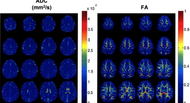
The diffusion coefficients, the ADC, and the FA describe the most of the important features of a diffusion tensor. An example of ADC and FA maps is shown in Figure 3-2 in the macaque monkey. ADC (mm2/S) xlo FA -4 3.5 3 2.5 2 1.5 1 0.5 n 0.8 0.6 0.4 0.2 e%
Figure 3-2. (Left) ADC and (Right) FA maps calculated from a DTI acquisition at 0.9 mm isotropic on a monkey. The FA, which is a measure of anisotropy, is highest in white matter.
The two other diffusion reconstruction methods are QSI and HARDI, which don't
assume a single mode of diffusion. Both QSI and HARDI calculate the orientation distribution
function. Here we limit our discussion to HARDI methods which are model independent, specifically Q-ball imaging (QBI)24.
3.2.2 Q-space Imaging (QSI)
Both QSI and QBI calculate the orientation distribution function. The angular distribution function or orientation distribution function (ODF), y(0,9), of the water molecules, represents the likelihood of water to diffuse in a particular direction, and can provide neuroscientists considerable information about microscopic brain architecture. Mathematically, it is defined as the radial projection of the average propagator onto the unit sphere.
J
(0,9) =Rf
(R,t)
dR
(3.9)
The ODF contains much more information than the diffusion tensor because it is capable of describing multimodal diffusion. QSI and QBI calculate the ODF using two different methods.
QSI measures the average propagator directly by sampling the diffusion signal on a three dimensional Cartesian lattice. The average propagator is then calculated by taking the 3-D inverse Fourier Transform of Eq. (3.1). The ODF is then calculated from the average propagator using Eq. (3.9). However, QSI suffers from two practical weaknesses. Because the technique requires gradient sampling on a three-dimensional Cartesian lattice, it is time-intensive. Furthermore, QSI requires large pulsed field gradients that may not be available for various types of MR scanners.
3.2.3 Q-ball Imaging (QBI)
To address the concerns of QSI, investigators proposed an approach based on sampling on a spherical shell (or combination of shells) in diffusion wavevector space. The spherical sampling approach is referred to as high angular resolution diffusion imaging (HARDI) 23,32,34 In
theory, the efficiency gain of HARDI would stem from need to sample only on a spherical shell as opposed to the three-dimensional Cartesian volume required by QSI. By selecting a sampling shell of a particular radius the acquisition could also be targeted towards specific length scales of interest. David Tuch has developed a reconstruction scheme for the HARDI data acquisition which is called Q-ball imaging (QBI)24. QBI is not as limited by SNR as QSI and scan times of
40 minutes are achievable with QBI. In QBI, the ODF is calculated by applying the Funk-Radon transform to the diffusion signal sampled on a spherical shell24.
3.2.4 Technical Limitations
Although QSI and QBI are capable of probing tissue architecture and neural connectivity, they suffer from two problems that limit its effectiveness and applicability; (i) low signal to noise/long scan times, and (ii) noise instability of the reconstruction algorithm. The SNR difficulties arise from the high wavevectors that are necessary to resolve the angular peaks in the diffusion signal. These high wave vectors give SNRs ranging from 2 - 10. In addition, the scan time is to long to be used consistently in a clinical setting ( > 30 minutes) 35.