Design and Characterization of a Compact Voice Coil
for a Needle-Free Injection Device
by
Diana Lui
SUBMITTED TO THE DEPARTMENT OF MECHANICAL ENGINEERING IN PARTIAL FULFILLMENT OF THE REQUIREMENTS FOR THE DEGREE OF
BACHELOR OF SCIENCE IN MECHANICAL ENGINEERING AT THE
MASSACHUSETTS INSTITUTE OF TECHNOLOGY
JUNE 2006
( 2006 Diana Lui. All rights reserved.
The author hereby grants to MIT permission to reproduce and to distribute publicly paper and electronic copies of this thesis document in whole or in part
in any mention now known or hereafter created.
ARCHIVES MASSACHUSETTS INSTITUTE MASSACHUSETTS INSTITUTE OF TECHNOLOGY AUG 0 2 2006 LIBRARIES Signature of Author. ...
Department of Mechanical Engineering May 12, 2006
Certified
by...
.
Certified
by
...
...
...Ian W. Hunter Hatsopoulos Professor of Mechanical Engineering and Professor of BioEngineering
% 1> Thesis Supervisor
Accepted by ...
, _...:
...
...
John H. Lienhard V Professor of Mechanical Engineering Chairman, Undergraduate Thesis CommitteeI
Design and Characterization of a Compact Voice Coil
for a Needle-Free Injection Device
by
Diana Lui
Submitted to the Department of Mechanical Engineering on May 12, 2006 in Partial Fulfillment of the Requirements for the Degree of Bachelors of Science in
Mechanical Engineering
ABSTRACT
Conventional needle-free injection (NFI) devices are driven by a pressure source generated by either a compressed spring mechanism or compressed inert gas, which have fixed injection (pressure versus time) profiles. The NFI device developed at the Massachusetts Institute of Technology BioInstrumentation Laboratory (MIT BiLab) is novel in its use of a Lorentz force voice coil actuator as the pressure source. With servo-control, the applied pressure can be adjusted for injection conditions such as skin toughness and injection depth. The focus of this thesis was on designing, building and characterizing a more compact version of the current NFI device. The proposed design features a reduction of the diameter of the voice coil motor by packing empty space with an additional set of magnets. A prototype was built, and benchtop tests were conducted to characterize its force sensitivity, the stability of this force sensitivity, and the jet velocity from the syringe. The force sensitivity was found to be 8.3 N/A, and its consistency was shown to be remarkably stable throughout the stroke of the voice coil. It was found that, with a 200 V input, the voice coil exerted a force of 127 N on the syringe piston, which is equivalent to 12.7 MPa; this pressure produced a jet velocity of 162 m/s out of the syringe.
Thesis Supervisor: Ian Hunter
Acknowledgements
First and foremost, I would like to thank Professor Ian Hunter for the privilege of working in the BioInstrumentation Laboratory. My time with the BiLab was brief, but it was an unforgettable and intellectually stimulating experience. I would especially like to thank Dr. Andrew Taberner for his guidance, patience and tremendous support throughout my thesis research, and Dr. Cathy Hogan for also proofreading this thesis and for her encouragement.
To my new friends at the BiLab, I had an amazing time working (late into the night) with you, and am inspired by your brilliance and talent. Thank you for the warm welcome, encouragement, and much-needed comic relief.
My heartfelt thanks also goes to the technical staff in the Pappalardo Laboratory-Joe Cronin, Steve Haberek, Bob Gertsen, and Bob Nuttal-for their support throughout all of my undergraduate years. A very special thanks goes to Joe, for always believing in me and for greeting me with a bright smile on all those (too) early mornings.
Most importantly, thanks to my family-Janet, David, and especially Mom and Dad-because none of this would have been possible if it weren't for you.
Table of Contents
Introduction ... 9
1 Background ... 10
1.1 Needle-Free Injection Technique . ... 10
1.2 History of N eedle-free Injection Technology ... 11
1.3 Existing Needle-Free Injection Technology ... .. ... 14
2 Current BiLab NFI Device ... 16
2.1 D esign D escription ... 16 2.2 Desired Improvements ... 18 3 Proposed Design ... 19 3.1 D etailed D escription ... 20 3.1.1 N dFeB M agnets ... 20 3.1.2 Voice Coil ... 22 3.1.3 Top Plate ... 23 3.1.4 Steel H ousing ... 24
3.1.5 Outer Plastic Shell ... 26
3.1.6 Bottom Cap ... 27
3.2 M anufacture of Prototype ... ... ...28
3.2.1 N dFeB M agnets ... 28
3.2.2 Steel Housing Shell ... 29
3.2.3 Steel Top, Front and Back Plates ... 29
3.2.4 Voice Coil ... 29
3.2.5 Outer Plastic Shell and Bottom Cap ... 29
3.3 A ssem bly of Prototype ...30
4 Characterization of Prototype ... ... ... ... 32
4.1 Force versus Current and Force versus Displacement ... 32
4.1.1 Experim ental Apparatus ... 32
4.1.2 Experim ental Procedure ... 33
4.2 D isplacem ent versus Tim e ... ... ... 33
4.2.1 Experim ental Apparatus ... 33
4.2.2 Experim ental Procedure ... 35
5 Results and D iscussion ... 36
5.1 Force versus Current ... 36
5.2 Force versus Displacement ... 36
5.3 Displacem ent versus Tim e ... 37
6 Conclusion and Recommendations ...40
References... 42 A ppendices... 44 Appendix A ... 44 Appendix B ... 45 Appendix C ... 46 A ppendix D ... 48 A ppendix E ... 50
Introduction
Since the invention of the hypodermic syringe in 1853, intradermal injection of medication has grown to be one of the mostly widely used methods of delivering drugs into the body, with as many as 12 billion injections per year [1]. By the time they are two years of age, average American children could have received up to 23 vaccination shots for protection against diseases such as polio and measles [2].
Despite tremendous advancements in needle and syringe technology, the intradermal injection process is still hazardous, inconvenient, complicated, costly and painful. Major issues concerning injection with a hypodermic syringe that still persist include: accidental needle-stick injuries, risks of contamination, needle phobia, and poor patient compliance. Needle-free injection (NFI) devices, which have existed since 1936, offer a safer, more convenient and more acceptable alternative to needle injections [3]. It is the process by which medications are pushed through an ultra-fine orifice at high pressure, thereby creating a high-speed stream of fluid that punctures the skin and underlying fat layer to deliver the drug without use of a needle.
This thesis describes the redesign, construction and characterization of an NFI device that was developed in the Massachusetts Institute of Technology BioInstrumentation Laboratory (MIT BiLab). Existing NFI devices consist of three core components: the pressure source, the medication cartridge and injection nozzle (orifice). The BiLab's NFI device differs from conventional devices in that the required pressure is generated by a custom-designed Lorentz force voice coil motor rather than by a spring mechanism or by compressed air.
The focus of this thesis was on designing a more compact version of the BiLab's NFI device. The diameter of the electromechanical motor was reduced by about a quarter, and the resulting power loss was compensated for with the addition of four bar magnets. A prototype of the proposed device was constructed, and tests were conducted to characterize its force sensitivity, the consistency of the force applied to the piston throughout the voice coil stroke, and the jet velocity of the fluid through the nozzle.
1 Background
1.1 Needle-Free Injection Technique
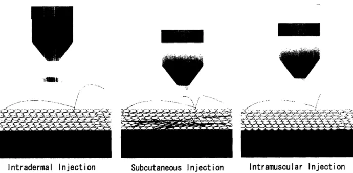
In needle-free injection, a high pressure pulse, generated either by the release of a spring mechanism or compressed air, ejects the medication through an ultra-fine orifice as a high-speed stream of fluid. This stream penetrates the skin and delivers the drug to the required depth-intradermal, subcutaneous or intramuscular, as shown in Figure 1.
Vaccines are typically administered with shallow intradermal injections or deep intramuscular injections, whereas therapeutic proteins such as human growth hormones are injected into the subcutaneous layer, or the fat layer below the skin.
EiAA:.
Intradermal Injection Subcutaneous Injection Intramuscular Injection
Figure 1: Needle-free injections are targeted at three different tissue depths: intradermal, subcutaneous and
intramuscular (drawing courtesy of David Lui).
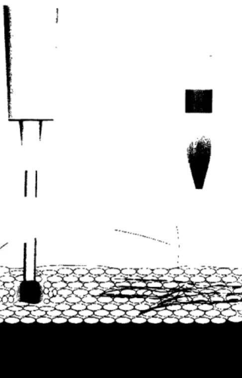
The typical needle size for delivering vaccines is 24-gauge, which has a nominal outer diameter of 559 tm. A high-speed stream ejected by the NFI device has a diameter that ranges from 76 to 360 pm, with 150 pgm being the most common orifice size [4]. In addition to the significant difference in size, the dispersion of the medication that is injected into the body also differs, as shown in Figure 2. Injection with a hypodermic syringe creates a bolus, or a ball of medication, at the tip of the needle; there is a wider dispersion pattern via injection with an NFI device.
·
i - -- ·- ·--..__ ___. i - _ \ i - - - __ --I~r-r .. '-"I'--- __ 1 --. 11'1'__'._ --- ~C~1 - I--_--r- _- "- -Y- T - - - Y -C _>r -e--? Co ~sf~'^~LC~~~'csC11
i ...- ... ...
1[:
Figure 2: Injection with a hypodermic syringe results in a bolus at the tip of the needle, whereas injection with the
NFI device shows a wider dispersion pattern (drawing courtesy of David Lui).
1.2 History of Needle-free Injection Technology
Whether to fight the common cold or as protection against diseases such as polio and cholera, medications need to be introduced into the body. The four traditional methods of delivering a drug into the body are orally, by inhalation, transdermally and parenterally, or by injection.
Due to advantages such as low cost and convenience, oral administration of medication is the most common method. However, some medications are not effective when administered orally, due to slow and/or unpredictable absorption rates. The incompatibility of these medications with the fluids in the digestive system is also a negative aspect of oral administration. These issues led to the development of alternative methods for drug delivery, such as nasal sprays and skin patches. Despite the increase in comfort with drugs delivered by inhalation or transdermally, the types of drugs that are suitable for these routes are limited.
The first hypodermic syringe capable of piercing the skin (see Figure 3), was developed independently by Dr. Charles Gabriel Pravaz of France and Dr. Alexander Wood of Scotland in 1853, and was used to locally inject morphine as a painkiller [5]. Injection with a hypodermic
syringe has many advantages over oral administration, including the flexibility of localized treatment, direct absorption of the drug into the bloodstream, and smaller dosage requirements.
Figure 3: The first hypodermic syringe invented by Dr. Charles Gabriel Pravaz in 1853 (copied from [6]).
Significant advances in the design of the syringe and needle over the past century, such as the mass production of disposable syringes, have vastly improved the efficiency, convenience and safety of injection technology. However, many important concerns are still unaddressed. Common issues with hypodermic needle injection include: complexity of injection techniques, risk of cross-contamination from needle-stick injuries, cost of sharps disposals, needle phobia, which perpetuates poor patient compliance, and pain at the injection site. Injection with a needle and syringe requires that the health-care providers have the skill set to properly insert the needle, inject the medication at a specific depth, aspirate to ensure that the needle is not in a blood vessel, keep the needle steady during injection, and avoid being stuck with the used needle [7].
Accidental needle-stick injuries are of major concern-an estimated 800,000 such injuries occur annually in the United States [8].
Although needle-free injection does not solve all the problems associated with injection via a hypodermic syringe, it is a safer and less painful alternative. Needle-free injection devices significantly reduce the cost and hazards of sharps disposals, as well as address the concern of needle-stick injuries. In addition, administration of medications with NFI devices is faster (typically taking less than 300 milliseconds), less complex, and less painful, three factors which are expected to increase patient compliance with regards to receiving treatment involving
injections [7]. Studies have shown that the wider dispersion pattern from a needle-free injection exposes more cells to the medication, thereby increasing the efficacy of the drug [9].
The needle-free technique, first developed in 1866 by B6clard in France as "Aquapuncture," was the technology from which American Marshall Lockhart designed a jet injection device in 1936 [3]. In the early 1940's, Robert A. Hingson, among other inventors, developed "guns" for jet injection. These devices were adapted for multiple-use for mass immunizations against diseases such as smallpox and measles in under-developed countries [10]. As shown in Figure 4, they were also used locally by the Department of Defense to administer as many as 40 million
vaccines between 1965 and 1980 to military personnel.
I
Figure 4: The Imo-JetTM jet injector is an example of the multi-use injectors adapted for mass immunization in under-developed countries and for U.S. military personnel (copied from [11]).
However, although it has considerable advantages over injection with a hypodermic syringe, needle-free injection technology, despite having existed for over 60 years, has not yet been widely adopted by professionals and individuals. In addition to concerns about contamination risks that resulted in the discontinuation of the use of the jet guns in the mid-1980s [12], issues related to needle-free technology include the inconsistency of jet injection, occasional drug pooling on the skin (wet injections), incomplete drug delivery, drug volume limitations, and localized bruising, pain and bleeding at the injection site.
Over the past few years, an increased focus on healthcare issues such as contamination risks and needle phobia have led to more emphasis on addressing the concerns relating to needle-free injection technology. Recently, an average of 4% of drug delivery deals have been linked to developing this technology [13]. In addition, results from clinical tests and studies by companies and researchers support needle-free injection technology; it has been shown that individuals experienced greater comfort with needle-free injection over conventional needle injections and that injection with NFI devices is just as effective as with a hypodermic syringe [7, 16].
1.3 Existing Needle-Free Injection Technology
The NFI devices that exist in today's market are designed for professional use by doctors to deliver drugs such as vaccines and growth hormones, and also for personal use by individuals for self-administering medications such as insulin. The core components of NFI devices are the pressure source, the medication cartridge, and injection nozzle (orifice). The device is driven either by a spring mechanism or by compressed inert gas, commonly nitrogen or carbon dioxide. Depending on whether it is disposable or reusable, the NFI device operates either with a pre-filled cartridge or with a cartridge to be pre-filled prior to injection.
Spring-powered devices, such as the Bioject "cool.click" shown in Figure 5, have the advantage in terms of size. They are small, light, durable and inexpensive. Disadvantages of these devices include the necessity of a mechanism to prevent accidental triggering of the coiled spring, a limit to the amount of force that the spring can generate, and the potential for incomplete drug delivery due to a decrease in pressure towards the end of the spring's uncoiling stage [16].
Figure 5: The Bioject "cool.clickM " is designed for injection of Saizen®, a growth hormone (copied from [16]).
1., It i
..
Gas-powered devices, such as the PenJetT Mshown in Figure 6, provide a more stable force. In addition, they can generate greater pressures, which in turn allow larger volumes of the drug to be delivered. Pitfalls with gas-powered injectors include possible gas leakage, operation temperature limitations, the loud noise generated upon firing, and the necessity of replenishing the gas supply, which can be costly. For both gas- and spring-powered devices, the injection profile (pressure versus time) is fixed, so the device lacks the flexibility of adjusting its parameters for skin condition variables such as toughness and sensitivity [15].
Figure 6: The PenJetTM is a disposable compressed-gas powered device designed to deliver medication in liquid and powder forms (copied from [17]).
The characteristics and dimensions of some of the more common devices in the needle-free market for individual home use are given in Table 1.
Table 1. Comparison of NFI devices [18-22].
Device Pressure Pre- Life Drug** Dosage Injection Length Mass
(Company) Source* filled cycle Depth+ (mm) (g)
Advanta Jet SP No -- I 0.5-50 mL SQ 165.1 172
(Activa Brand)
Medi-Jector Vision SP No 3,000 I, HGH 2-50 units SQ 152.4 130
(Antares Pharma) insulin
Intraject (Aradigm) CN Yes 2 -- 0.5 mL SQ 120.0 180
Vitajet SP -- 3,000 I 2-50 units SQ 152.4 158
(Bioject) insulin
Crossject GG Yes 1 -- 0.2 to 1 mL ID, SQ, IM 83.0 80
Injex 30 SP Yes 7,000 I, A 0.02 - 0.5 mL I SQ 139.7 77
(Injex Equidyne) 0.3 mL A
PenJet CN Yes 1 I,V 0.1- 0.5 mL ID, SQ, --
--some IM * SP = spring, CN = compressed nitrogen, GG = gas generator
** I = insulin, HGH = human growth hormone, A = anesthesia, V = vaccines +ID = intradermal, SQ = subcutaneous, IM = intramuscular
issa
CT--
AL_1h.MW_B' "~ ~~~~~~~~~~~~~~~~~~~
- " " · - ""··· ·
2 Current BiLab NFI Device
2.1 Design Description
The current design of the portable NFI device developed at the BiLab is shown in Figure 7. This needle-free injector is novel in its use of a custom-designed Lorentz-force actuator to generate the pressure required for needle-free injection. The major advantage that an electromechanically actuated device has over those that are spring- and compressed gas-powered is that, with servo control, the applied pressure can be adjusted while injection is occurring. In addition to improvements to the quality and depth of drug delivery, control of the pressure profile allows for specification of the medication and injection conditions such as skin type and location [23].
Figure 7: The most recent version of the portable NFI device developed at the BiLab (photo courtesy of Dr. Andrew
Taberner, a Research Associate with the BiLab).
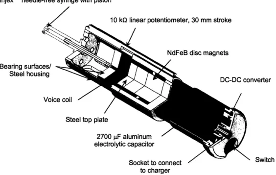
A cutaway view of the Solid Edge® model of the device is shown in Figure 8. The device, which is powered by a high energy and high power density aluminum electrolytic 2700 jiF capacitor, is rechargeable, and operates once per 90-second recharge period. The custom-designed voice coil actuator system consists of two 0.4 MN/m2 (50 MGOe) neodymium (NdFeB) rare-earth disc magnets nestled within a coil of 28 gauge copper wire wrapped around a thin-walled Acetal copolymer former. The syringe, a disposable InjexTM NFI ampule with a drug volume of 300 pL, screws into the top of the steel housing. A commercially available vial adapter enables the user to transfer pharmaceutical liquids from their vials into the ampule [23].
Injex'M needle-free syringe with piston
10 k linear potentiometer. 30 mm stroke
Bearing surfaces/ Steel housing
Voice
Steel top plate
/ nverter / 2700 F aluminum / electrolytic capacitor Socket to connect to charger -/z NX Switch
Figure 8: Cutaway view of the device showing major components, excluding the outer plastic shell (solid model by
Dr. Andrew Taberner).
Bench-top tests, in which a 4 kW linear power amplifier rather than the capacitor was used to power the device, were conducted to evaluate the effectiveness of the voice coil motor. From these tests, the force sensitivity was found to be 11.5 N/A at mid-stroke. The force generated by the voice coil was more than 200 N (- 20 MPa on the fluid) with an applied voltage of 200 V. Repeatability tests yielded an average drug delivery volume of 50.9 1 gL. Table 2 provides a
summary of the major characteristics of the device.
Table 2. Characteristics of the current device [23].
Characteristic Units
Length 219.05 mm
Width 44 mm
Mass 0.5 kg
Wire material Copper Wire diameter 360 tm Voice coil, number of turns 582
Voice coil, DC resistance 11.3 Q Stroke length 25 mm Flux density 0.6 T Force sensitivity 11.5 N/A
2.2 Desired Improvements
One improvement to the functionality of the device that is currently under development is the design of a closed-loop control system to allow real-time adjustments to the force, pressure and displacement of the electromechanical motor.
In addition to the incorporation of real-time control, changes to the overall size and shape, ergonomics and power of the device were desired. Since it uses an electromechanical motor, the current device is significantly wider than conventional devices, which are on average about 25 mm wide. Its length, however, is only slightly longer by about 50 mm. A more compact voice coil motor design will also allow more flexibility with the design of the outer plastic shell.
3 Proposed Design
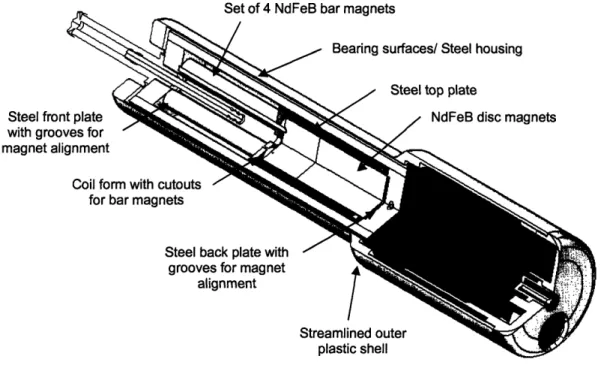
The focus of this thesis was on exploring a more compact design that was proposed by Dr. Andrew Taberner. The diameter of the voice coil motor was reduced and a set of bar magnets was added above the steel top plate to enhance the power of the voice coil at the end of its stroke.
Figure 9: The more compact version of the NFI device has a smaller diameter and incorporates a second set of
NdFeB magnets.
The basic structure of the current device was kept intact. Dimensional changes include an approximate 50 mm decrease in diameter, a 70 mm increase in length and, due to the additional magnets, a 0.02 kg increase in massive. Its characteristics are shown in Table 2.
Table 2. Characteristics of the proposed design.
Characteristic Dimension
Length 226.15 mm
Width 35.1 mm
Mass 0.52 kg
Wire material Copper Wire diameter 360 gum Voice coil, number of turns 834
Voice coil, DC resistance 12.9 Q
Stroke 30 mm
3.1 Detailed Description
Most of the design of the proposed device was based on that of the current injector. The modified components and new elements are highlighted in the cutaway view in Figure 10. The reasoning for the design decisions for the components will be explained in the following sections.
Set of 4 NdFeB bar magnets
/
Steel front plate with grooves for magnet alignment
Coil fo
for
Figure 10: Cutaway view of the proposed design showing major modifications and new components. 3.1.1 NdFeB Magnets
Neodymium magnets, composed of iron, boron and mostly neodymium, are the most powerful permanent magnets in the world. The magnet grades vary from N24 to N50, with the latter being the strongest with an energy product of 50 MGOe. Neodymium magnets were chosen for this application because they are relatively inexpensive and have an extremely high energy density, which was ideal for making the design as compact as possible.
The current design consists of just one set of two 25.40 mm NdFeB disc magnets with a total height of 19.05 mm centered inside the voice coil on the back plate of the steel housing shell. The magnetic circuit of this design is shown in Figure 11.
Coil Winding
Back Plate
Steel Housing
eel Top Plate
Figure 11: Magnetic field lines of the voice coil of the current injector design.
Figure 12a shows a cutaway view of the voice coil motor component of the current device. The magnets take up less than half the volume within the shell. The proposed design (see Figure 12b) makes use of this space by packing it with another set of magnets. Since the additional magnets increase the strength of the magnetic field, a reduction of the diameter of the voice coil magnets to 19.05 mm while retaining the strength of the magnetic field was feasible.
Empty space
(a) (b)
Figure 12: Cutaway view of the voice coil assembly of the (a) current design and (b) proposed design.
The four bar magnets, 6.35 mm in diameter, were placed on the other side of the steel top plate so that they repelled the disc magnets, which produces the magnetic circuit shown in Figure 13. Ideally, the bar magnets would have the same cross-sectional area as that of the disc magnets so that the magnetic fields produced by both sets of magnets are identical.
Back Plate
Steel Housing
Ago Front Plate
a pbft
Figure 13: Magnetic field lines of the voice coil of the proposed injector design.
3.1.2 Voice Coil
The voice coil, shown in Figure 14, is 54 mm in length and 25.40 mm in diameter. It was desired for the voice coil to have a stroke of at least 30 mm. Since the steel top plate needs to be within the coil during its entire stroke, the minimum length of the coil is the sum of the height of the top plate, 16 mm, and the stroke. The axial length of the former around which the coil was wound was set at 48 mm.
The wire used for the coil is 28 AWG gauge copper wire, which has a diameter of 360 gm. The current NFI design has six layers of windings; to allow at least this many layers, the diameter of the former around which the wire will be wound needs to be about 4 mm less than that of the bearing surfaces on the proposed design. The diameter of the former was set at 21.4 mm, with a wall thickness of 1 mm. The bearing surfaces added 3.5 mm to each end of the voice coil.
For a coil with these dimensions, each layer will have an estimated 139 turns; for the proposed six layers, this equals 834 turns for the entire voice coil. The theoretical coil resistance can be calculated with the number of layers, the coil's length and diameter and the wire's diameter and resistance/km. The number of turns per layer can be determined by dividing the length of the coil by the wire's diameter. The increase in the coil's diameter for each additional layer of wire was calculated to be 0.26 mm; since each layer is staggered with respect to the previous one, each layer increases the coil diameter by 312 gm. The overall length of the wire in the coil is equal to the sum of the length of wire in each layer, and was calculated to be 60.89 m. The resistance per
unit length of 28 AWG copper wire is 0.213 Q/m, so this coil is expected to have a resistance of 12.96 Ql. Refer to Appendix A for the detailed calculation of this resistance.
Grooves for magnet
alignment
Bearing surfaces
Figure 14: Comparison between the voice coils of the (a) previous and (b) proposed designs.
This device was designed to be used with a disposable syringe that is manually filled with a vial adapter. When screwed into the top of the device, the piston of the syringe is free hanging until it is moved by the top surface of the voice coil when the device is fired. As shown in Figure 14, a 2.5 mm hole has been drilled through the center of the top surface as a placement guide for the piston. The pattern of four holes is necessary for the alignment of the bar magnets.
3.1.3 Top Plate
The purpose of the steel top plate is to direct the field lines of the disc and bar magnets radially outwards through the voice coil and across the air gap. The steel top plate for the old design is a simple disc with a diameter and height of 25.40 mm and 8 mm, respectively. With the addition of the second set of magnets, the length of the top plate (see Figure 15) was doubled in order to provide enough length for the magnetic field lines to bend outwards. The diameter of the top plate is equal to that of the disc magnets, 19.05 mm.
The cross-sectional area of the top plate determined how many bar magnets would fit into the available space within the voice coil. Although it is feasible to fit five magnets on the top plate, that configuration did not leave enough clearance between the magnets for the coil to travel through. Since the magnets are constantly repelling, 1 mm deep grooves were put on the top
surface of the plate for exact placement of the magnets. The grooves are 6.35 mm in diameter and 5.82 mm from the center of the top plate.
Figure 15: The front plate has four grooves to ensure proper alignment of the bar magnets.
3.1.4 Steel Housing
3.1.4.1 Shell
The steel housing shell is shown in Figure 16, along with the design for the current NFI device. The diameter and height of the current shell design is 44 mm and 104 mm, respectively. Some sections of the top half of the shell have been cut out to decrease its mass. For the proposed design, the shell is solid to complete the magnetic circuit of the voice coil.
voice coil to extend to
capacitor
(a) (b)
Figure 16: The housing shell for the (a) current NFI design and (b) proposed design; the shell for the proposed
design is slimmer but longer.
The shell also acts as a bearing surface for the voice coil, so its inner diameter is 25.40 mm. To be sure that the shell is not saturated by the magnetic field lines, the cross-sectional area was designed to be at least that of the disc magnets, which is 2.85x 10- 4m3. The thickness of the shell was calculated to be 6.35 mm, so the outer diameter is 31.75 mm.
Two slots 3.175 mm wide were designed to allow the two ends of the voice coil wire to extend from within the shell to be connected to the capacitor at the bottom of the NFI device. For coverage of the entire stroke of the voice coil, the slot length was set at 35 mm.
The shell has a total length of 112.50 mm. The front and back plates of the housing will be attached to the shell with M2.5x8 cheese head screws. Four holes 2.50 mm in diameter were designed at each end for positioning of the screws, and grooves 5 mm in diameter and 3mm deep will ensure that the top of the screw caps are flush with the outer diameter of the shell.
3.1.4.2 Front and Back Plates
The front and back plates for the steel housing, shown in Figure 17, are identical to those of the old design, with the exception of the 1 mm deep grooves for placement of the magnets. The same four-groove configuration on the top plate was used for the front plate. The front plate also has a 6.75 mm hole in the center that will be threaded to allow the InjexTM disposable syringe to screw into the device. The back plate has one groove 19.05 mm in diameter to ensure that the disc magnets at the rear of the device will be centered. The four holes 2.05 mm in diameter through
the sides are for attachment to the housing shell.
yringe screws into hole
Grooves for placement
(a) of magnets (b)
3.1.5 Outer Plastic Shell
Many designs were considered for the outer plastic shell, as the decrease in diameter of the voice coil motor allowed more flexibility in streamlining the front end of the device. The shapes of both conventional compressed-gas-powered NFI devices and electronic toothbrushes, such as the ones shown in Figure 18, were explored as possible models for the shell design.
(a) (b) I
_~~~~~~~~~~~~~~~~~~~~~~~~~~~~~~
Figure 18: (a) Conventional NFI devices and (b) electronic toothbrushes were used as models for the plastic shell
design (copied from [21, 24-25]).
However, since the conventional NFI devices are in general shorter and slimmer, their shapes are less appealing when scaled up to the size of the proposed NFI device. Although electronic toothbrushes are similar in size to the NFI device, the way in which they are held is opposite; the toothbrushes are gripped with the bottom of the palm pointing towards the base of the device, whereas he NFI is held with the bottom of the palm pointing towards the front end (see Figures 7
and 9). The ergonomics of the design therefore cannot be adapted.
Some of the designs that were considered are shown in Figure 19a. The incorporation of finger grooves onto the shell was considered; however, since it was difficult to determine a grip size to fit the average user, the grooves were discarded in the final design. A curved streamline to improve the ergonomics of the device was also explored. Although this design is less harsh than the taper of the first design, it was decided for the final design to have straight edges with slightly tapered or rounded edges, as shown in Figure 19b. The thickness of the shell is 1.25 mm.
'. "i 9
(a) (b)
_
Figure 19: (a) Designs considered for the outer plastic shell, and (b) the selected design.
3.1.6 Bottom Cap
The bottom cap assembly, shown in Figure 20, consists of the capacitor, a DC-DC converter, a push-button switch and the socket that connects the NFI to the charger. It is identical to that of the current NFI device, with the exception of a ledge that holds the capacitor in place.
positioning
citor
Figure 20: The bottom cap assembly consists of the capacitor, a DC-DC converter, socket and a push-button switch. I
3.2 Manufacture of Prototype
This section describes the manufacture of each component of the device, as well as the assembly process. The parts are shown in Figure 21.
Figure 21: (a) Grade N42 NdFeB disc magnets, (b) Grade N42 NdFeB bar magnets, (c) steel housing shell, (d) front
plate, (e) back plate, (f) voice coil, (g) top plate and (h), bottom cap. 3.2.1 NdFeB Magnets
The magnets used in this device are 0.336 MN/m2 (42 MGOe) NdFeB. The grade of the magnets
was chosen because of product availability. Two disc magnets, 25.40 mm and 6.35 mm in height and 19.05 mm in diameter, were combined for a total bottom magnet height of 31.75 mm. The top magnet set consists of four bar magnets 6.35 mm in diameter. The length of both sets of magnets should be identical. However, due to limitations of stock magnet sizes, bar magnets
50.80 mm in length were used. To prevent unnecessary coil movement beyond the desired 30 mm stroke because of this extra length, plastic tubing was fitted onto top ends of the bar magnets to act as stoppers.
3.2.2 Steel Housing Shell
The housing shell was constructed from 1026 low-carbon steel tubing. Low-carbon steel was chosen for its high magnetic permeability and high saturation limit. The four holes at each end of the plate were drilled 4 mm from the edges of the shell. For proper alignment, the front and back plates were carefully placed into the shell, and the holes for the M2.5 thread were drilled concentrically with those of the shell. The slots were made with a 3.175 mm end mill.
3.2.3 Steel Top, Front and Back Plates
The steel top plate was constructed from a 1018 low-carbon steel rod cut and faced off to length at 16 mm. The four grooves were then milled using the bolt pattern feature on the CNC mill. The front and back plates were also constructed from 1018 low-carbon steel. The same bolt pattern for the top plate was used for the front plate, and the groove for the back plate was made with a 19.05 mm end mill. After the hole through the center of the front plate was drilled, an M8 tap was used to create the thread for the ampule to screw into the device. The holes on the sides of the front and back plates were also tapped for M2.5 screws.
3.2.4 Voice Coil
To keep the mass of the moving voice coil to a minimum, Delrin® acetal resin was chosen as the former material. Even though Delrin® has a low operating temperature range with a maximum of 150°C, heating of the coil is not expected to be an issue since injection typically occurs in less than 300 ms. The material was cut to length, and the outer diameter was turned down to 21.40 mm before the inside of the coil former was hollowed out. The holes through the top surface of the voice coil were drilled last; again, the bolt pattern feature on the CNC mill was used for the magnet holes.
3.2.5 Outer Plastic Shell and Bottom Cap
The outer shell and bottom cap for the device were printed with resin on the 3D Systems® ViperT M stereolithography machine. After printing, excess resin was cleaned from the parts. The
parts were then put into a UV oven for 2 hours to harden. Afterwards, the parts were sanded down to remove any roughness, and spray painted with white Krylon® Fusion for Plastic superbond spray paint.
3.3 Assembly of Prototype
The two disc magnets were aligned together and set into the groove of the back plate. The top plate was then aligned with the magnets, and the voice coil placed over them. The top plate and coil form were then adjusted to the position that would enable the wires from the voice coil to go through the slots of the housing shell. The four bar magnets were then placed through the holes in the voice coil and set into their respective grooves on the top plate, with care taken to ensure that the disc magnets and bar magnets are repelling. The top front plate was then fitted onto the top of the bar magnets, thus completing the voice coil assembly that is shown in Figure 22.
Figure 22: The voice coil motor assembly that fits within the steel housing shell.
The voice coil assembly was then pressed into the housing shell from the top. The wires and screw holes were aligned with the slots and holes of the housing shell, and the assembly was carefully lowered down. The wires were pulled through the slots and the voice coil was moved up and down to check for proper alignment of the bar magnets. Lastly, M2.5x8 screws were used to hold the entire assembly together. The syringe was then screwed into the front plate, which results in the completel prototype assembly shown in Figure 23b. The voice coil motor of the
Figure 23: A comparison of the (a) old NFI voice coil motor assembly and (b) proposed design.
Assembly of the bottom cap consists of bonding the DC-DC converter, socket and push button switch into their respective slots. The voice coil assembly is then fit snugly into the outer plastic shell, and attachment of the bottom cap completes the assembly of the NFI device.
4 Characterization of Prototype
4.1 Force versus Current and Force versus Displacement
The force sensitivity of a voice coil motor is the amount of force generated per current through the wire. To determine the force sensitivity, it was necessary to measure the force as a function of current. The stability of this force throughout the stroke of the voice coil can be measured by plotting the force on the piston with respect to displacement.
4.1.1 Experimental Apparatus
The experimental apparatus in Figure 24 consists of the needle-free injector prototype and a Shimpo FGV-1X digital force gauge mounted on a platform with Macrobench components, and an Agilent E3631A Power Supply. The force gauge was centered axially with the device, and measures the force on the syringe piston by the voice coil. The force gauge is mounted on a platform with a micrometer with a length range of 25 mm, and outputs data in units of Newtons.
Figure 24: Experimental apparatus for measuring the force on the syringe piston with respect to current and voice
4.1.2 Experimental Procedure
4.1.2.1 Force versus Current
The device was connected to the +25 V output on the power supply. The voltage current and limits were set to 25 V and 1 A, respectively. The micrometer was used to move the force gauge away from the device until about where the voice coil reaches mid-stroke, which is about 10 mm from the bottom of the device. This ensures that measurements are taken when the force is strongest and most stable (refer to Figure 13). The power supply output was turned on, and the force output was read for values of current between 0 and 1 A in increments of 0.05 A.
4.1.2.2 Force versus Displacement
The coil and piston were positioned at the back end of the device. The force gauge was moved up to the piston until a small positive force output was read on the gauge. The micrometer was then used to carefully retract the gauge until the output read 0 N. The device was attached to the +6 V outputs of the power supply, and the voltage and current limits were set to 5.5 V and 0.5 A, respectively. The power supply output was then turned on, and force values for displacements up to 23 mm were taken in increments of 0.5 mm. The force sensitivity was calculated by dividing the force by the current.
4.2 Displacement versus Time
To characterize the jet velocity of the fluid, it was necessary to measure the displacement of the voice coil with respect to time. This displacement is equivalent to the displacement of the piston within the syringe; from this relationship, the volumetric flow of the fluid can be used to determine the jet velocity through the orifice of the syringe. Also, to determine the pressure applied to the fluid by the voice coil, it was necessary to measure the current with respect to time. The relationship between the force sensitivity, force and area of the piston can then be used to find the pressure applied to the piston.
4.2.1 Experimental Apparatus
The setup for this experiment, shown in Figure 25, consists of a LabviewTM Virtual Instrument (VI) control platform, a National Instruments BNC-2120 data acquisition (NI-DAQ) block, an AE Technron LVC Linear Amplifier with a 20 A limit, the NFI device and a 10 kQ linear
potentiometer with a 30 mm stroke. The VI, shown in Figure 26, was used to send a voltage signal as a user-specified waveform, and the amplifier was used to achieve voltage outputs up to 200 V. The linear potentiometer was positioned next to the voice coil to read its displacement.
Figure 25: Experimental apparatus for measuring the applied voltage, current and displacement of the voice coil as
a function of time.
The NI-DAQ block was set up to acquire data for the time, the displacement of the voice coil, the supply voltage and the current. The voltage waveform was designed to deliver the voltage over a specified time interval.
ile b(V
O"6m (-)
Vobg. V) Pwdod (u)
Lzw
V' 2 Offst ;P E Delgned Wveform ls 17S Fire Load syrine US -1s LS -17.0 -1.0 -1i.0 5. -14.0 MS -wo -2.0 50 A e 3.0 -. 0 -5.o 38 -6. -=-TU 1T- -v- . Hi D. :i.:5g1~~l .65-14 7 --072 '27.9329 t*. _j Volume .bIt;e ' ' 1 6s6c024 C. . (A; . i J ,Dss&r:rerrt -, %Figure 26: Control panel of the LabviewTM VI used to control the voltage waveform (printed with permission from Dr. Andrew Taberner).
4.2.2 Experimental Procedure
For this experiment, the voice coil was moved to the very beginning of its stroke, and the syringe was filled with 0.25 mL of water before being screwed into the device. The NFI was fired three times for the specified voltages with each filling. The voltage waveform was varied from 100 V to 200 V in increments of 20 V, and set to act over a time interval of 50 ms.
_^1_ ___11_1_
a
T.mi
5 Results and Discussion
5.1 Force versus Current
The force sensitivity of the voice coil was calculated by dividing the force on the piston by the current; on Figure 27, it is the slope of the line. The average force sensitivity was 8.15 ± 0.14 N/A. At mid-stroke, the peak value was 8.33 N/A. The force sensitivity achieved by the proposed design is roughly 75% that of the current design, which had an average force sensitivity of about 10.8 ± 0.5 N/A, with a peak of 11.5 N/A at mid-stroke. Since the proposed design used magnets of grade N42, which have about 80% of the strength of the N50 magnets used in the current design, it is expected that the force sensitivity of this design will be comparable if N50 bar magnets were used. Refer to Appendix B for the acquired data.
a_
5 4z
3 o 0U2
1 0 0.1 0.2 0.3 0.4 0.5 0.6 0.7 Current (A)Figure 27: The force sensitivity of the voice coil motor is the force divided by the current.
5.2 Force versus Displacement
The plot of the force sensitivity with respect to displacement (see Figure 28) shows that the force sensitivity is highest in the mid-stroke region, from approximately 5 to 15 mm of displacement from the base of the NFI device (refer to Appendix C for the acquired data).The consistency of the values for force sensitivity shows that force generated by the piston is mostly stable throughout its stroke. Since conventional voice coil motors typically have larger variations in the force sensitivity, the consistency of this device is especially notable.
There is, however, some tailing off at the end of the stroke. This slight decrease can be attributed to fringing effects at the poles of the bar magnets by the top plate, and also because the cross-sectional area of the bar magnets is only approximately 60% that of the disc magnets, so the magnetic field in the upper end of the top plate is slightly weaker.
10
--- - - - ---__'____
0 5 10 15 20 25
Displacement (mm)
Figure 28: A plot showing the consistency of the values for the force sensitivity.
5.3 Displacement versus Time
The acquired data for the displacement, current and voltage with respect to time were used to find the pressure applied to the piston and the velocity of the fluid out of the syringe. The pressure and displacement curves for a waveform of 200 V applied over 50 ms are shown in Figure 29. For this experiment, the piston moved about 8.1 mm and imposed a pressure of approximately 12.7 MPa on the piston. The pressure was calculated by first multiplying the current through the coil by the force sensitivity. This gave the force of the voice coil, which was then divided by the cross-sectional area of the syringe, 3 ... 1 x 10⁻⁵ M2, to get the pressure.
x 106 15 a ID = 02) 0-o3 10 5 0 25 E
220
c 15 a) E a 0 Cu .B5 (6 O30 /..--.---... --- - -- --- -- --- - - --- - - ---- - ---- - ---0 0.005 0.01 0.015 0.02 0.025 0.03 0.035 0.04 0.045 0.05 Time (s) : I ~ .... ~~~~~~~~~~~~~~~---,d: - - - --- ----~---T---
- -4 =
--
--- I--- --- ----I J __________________ L , ---.... ---... . . . . ...--...,-...---.... . - . . . - - - . . . - - - . . . - - - . . . . - - - . . . . - - - - -T - - -T- - - -- - - --- --- --- --- --- ---~~~~~~~~~ ~ ~ , -- ---- ---- ,, -,, --- --- --- ---', -- --- ---- -- , , - - - -I- : -0 0.005 0.01 0.015 0.02 0.025 0.03 0.035 0.04 0.045 0.05 Time (s)Figure 29: The pressure profile and displacement versus time behavior for the voice coil driven by 200 V.
The displacement of the piston in the 50 ms interval was used to find the velocity of the piston,
Vpston, which was then used to find the volumetric flow rate, Liters, of the fluid through syringe,
Vl iters = 000 'meters = 1000 piston Apiston
The jet velocity, viJet, of the fluid out of the syringe was then solved for, with
Liters
Vi t Apiston
piston
(1)
(2)
The theoretical velocity of the fluid out of the syringe can be calculated with Bernoulli's equation for a steady, inviscid, incompressible and adiabatic flow (see Equation 3). The jet velocity, , can be calculated when the pressure on the piston is known,
2P
p=l- (3)
The theoretical and experimental values for the jet velocity are shown in Figure 30. The difference between the theoretical and experimental values ranges from 1 to 10%.
4 I OU 170 160 150 140 E '3 130 0 0, - 120 110 100 90 Rn 0.4 0.6 0.8 1 1.2 1.4 1.6 Pressure (Pa) x107
Figure 30: A comparison of the theoretical jet velocity and the values measured from the experiments. It has been shown that the device, with a 200 V input, can produce a jet velocity of 162 m/s. In literature about jet injections, it has been shown that for an orifice size of 162 pim, a jet velocity between 80 to 100 m/s is required to penetrate the skin [4]. The orifice of the syringe is 165 gm in diameter. These results show that the proposed voice coil motor, when driven with as low as 100 V, is sufficient to penetrate the skin. Refer to Appendix D for the MATLAB code used to solve for the theoretical and experimental jet velocities, and to Appendix E for a tabular comparison between theoretical and experimental values.
6 Conclusion and Recommendations
The purpose of this thesis was to explore an alternative design for the Lorentz force voice coil that is used in the portable NFI device developed at the BiLab. This design further compacted the device with four additional bar magnets that occupy the space within the voice coil at the end of its stroke. The addition of the magnets allowed for a decrease in the diameter of the voice coil motor, so the new design is slimmer by about 50 mm, but longer by about 70 mm and more massive by approximately 0.02 kg. The smaller diameter also allowed for a better streamline in the design of the outer plastic shell.
A prototype of this design was created to measure characteristics such as its force sensitivity, the stability of this force sensitivity, and the jet velocity of the fluid propelled out of the orifice of the syringe. The peak force sensitivity measured for this device is 8.3 N/A, and it was shown that this sensitivity showed remarkable stability throughout the stroke of the voice coil. The values for the jet velocity of the fluid as a result of the force on the piston by the voice coil were also shown to follow the theoretical curve, with less than 10% difference. With a supply voltage of 200 V, the voice coil was shown to exert 127 N of force on the piston, which is equivalent to 12.7 MPa of pressure. The velocity of the ejected fluid was 162 m/s, which is sufficient to pierce the skin.
One significant way in which this design can be improved is to change the magnets. The magnets used in this design, grade N42, were selected due to product availability. The magnets have only 84% of the strength of the highest grade, N50. It is hypothesized that if N50 magnets were used, the force sensitivity of the motor may also scale up to a possible increase of about 10 N/A.
In addition, it is worth exploring a similar design that applies the same concept of filling the empty space with magnets. Rather than bar magnets, custom-made neodymium magnets in wedge-shaped pieces will most closely provide the same cross-sectional area of the disc magnets. The coil form for this configuration is shown in Figure 31.
The set of four bar magnets used in the current design sum to roughly 60% that of the disc magnets, but it is able to achieve a force sensitivity of 8.3 N/A. This suggests that stronger magnets and a greater cross-sectional area can potentially increase the power of the device so
that it at least matches that of the current device. The ease of machining the components for the device will also be simpler with this design, since only a single 19.05 mm groove rather than a groove pattern is all that is necessary to keep the magnets in place on the front and top plates. When placed within the groove, the magnets will naturally separate into the alignment shown in Figure 31 due to repulsion.
Figure 31: Another alternative to the magnet structure to compact the space within the voice coil is to use
custom-made wedge-shaped magnets.
Another suggestion is to wind the voice coil motor with a larger gauge wire, such as 26 AWG. Since the voice coil of the new design is longer than that of the old one, it has a higher resistance, about 13.1 Q compared to 11.3 Q. The larger gauge will decrease in the resistance of the coil, which will allow more current to flow through the coil for a given supply voltage.
As with the current design, incorporation of servo-control will allow the motor force, pressure and displacement of the voice coil to be adjusted in real-time, which is an improvement to the fixed pressure profiles of conventional devices. Though its widespread acceptance has been surprisingly slow since its development in the 1940's, needle-free injection technology is gaining more attention and is expected to be a major focus of injection technology in the near future.
References
[1] Voelker, R. "Eradication Efforts Need Needle-Free Delivery." Journal of the Medical Association 281 (1999): 1879-1881.
[2] NIP: Vacsafe/Concerns/Gen/Safety of Multiple Vaccines. 9 Feb. 2005. Centers for Disease Control and Prevention. 01 May 2006.
<http ://www.cdc.gov/nip/vacsafe/concems/gen/multiplevac.htm# 1 >.
[3] Lockhart, M. Hypodermic Injector. U.S. Patent and Trademark Office. Patent 2,322,244. 22 June 1943.
[4] Schramm, J., Mitragotri, S. "Transdermal Drug Delivery by Jet Injectors: Energetics of Jet Formation and Penetration." Pharmaceutical Research. 19 (2002): 1673-1679.
[5] Levy, A. "Advances in disposable needle-free injector technology." Innovations in Pharmaceutical Technology. June 2000: 100-109. 01 May 2005.
<http://www.iptonline.com/articles/public/IPTFIVE 100NP.pdf>.
[6] "Pravaz-type hypodermic syringe, late 19th century." No date. Online image. Science &
Society Picture Library. 01 May 2006.
<http://www.scienceandsociety.co.uk/results.asp?image=10284534&wwwflag=2&imagepos=3>.
[7] Bioject. 2002. Bioject. 01 May 2006. <http://www.bioject.com/ >.
[8] United States Dept. of Labor. Occupational Safety and Health Administration. How to
Prevent Needle-stick Injuries: Answers to Some Important Questions. 1999. 01 May 2006.
<http://www.osha. gov/Publications/osha3161 .pdf>.
[9] Kerum, G., Profozic, M., Skrabalo, G., Skrabalo, Z. "Blood glucose and free insulin levels after the administration of insulin by conventional syringe or injector in insulin treated type 2 diabetics." Hormone and Metabolic Research. 19 (1987): 422-425.
[10] Hingson, R.A., Davis, H.S., Rosen, M. "The historical development of jet injection and envisioned uses in mass immunization and mass therapy based upon two decades experience." Military Medicine. 128 (1963): 516-524.
[11] "Imo-JetTM Injection." No date. Online image. National Immunization Program. 01 May 2006. <http://www.cdc.gov/nip/dev/images/IM-O-JET-Injectionjpg>.
[12] Levine, M.M. "Can needle-free administration of vaccines become the norm in global immunization?" Nature Medicine. 9 (2003): 99-103.
[13] PharmaVentures Ltd. The Pain and Pain-Free Side of Needle-Free Injections. Oxford, UK: PharmaVentures Ltd, 2004.
[14] Silverstein, J.H. Murray, F.T., Malasanos, T., Myers, S., Johnson, S.B., Frye, K., Grossman,
M. Clinical testing results and high patient satisfaction with a new needle-free device for growth hormone in young children. Endocrine. 15. 1 (2001): 15-17.
[15] PharmaVentures Ltd. Needle-Free Injectors: New Technologies. Oxford, UK: PharmaVentures Ltd, 2001/2002.
[16] "Bioject cool.clickTM." No Date. Online image. Bioject. 01 May 2006. <http://www.bioj ect.com/cool_click.html>.
[17] "PenJetTM." 2002. Online image. PenJet. 01 May 2006. <http://www.penjet.com/>. [18] VitajetTM. Bioject. 01 May 2006. <http://www.bioject.com/vitajet3.html>.
[19] Injex 30TM. Equidyne Systems. 01 May 2006. <http://www.injex.com/products/injex30.asp>.
[20] CrossjectTM. Crossject. 01 May 2006.
<http://www.crossject.com/pages/technologyproduct.htm>.
[21 ] Medi-Jector Vision T . Antares Pharma. 01 May 2006. <http://www.mediject.com/>.
[22] IntrajectTM. Aradigm. 01 May 2006. <http://www.aradigm.com/tech/intraject.html>.
[23] Taberner, A.J., Ball, N.B., Hogan, C., Hunter, I.W. "A Portable Needle-free Jet Injector Based on a Custom High Power-density Voice-coil Actuator." Proceedings of the 2 8th Annual
Conference of the IEEE EMBS2006, submitted for publication.
[24] mhi-5OOTM. Medical House Products Ltd. 09 May 2006. <http://www.insulinjet.com/>.
Appendices
Appendix A
MATLAB script for calculation of the theoretical voice coil resistance
pi=3.14159;
C_L=0.0480; %length of voice coil former C D=0.0214; %diameter of voice coil former W_D=0.000360; %diameter of copper wire
W_H=sqrt(WDA2 -(W_D/2)^2); %height for staggered layer of wires CD2=C D+2*W H; C D3=C D2+2*W H; C D4=C D3+2*W H; C D5=CD4+2*WH; C D6=CD5+2*WH; N_per_Lyr=C_L/W_D; N=139; L_Lyrl=pi*N*C_D; L_Lyr2=pi*N*C_D2; L_Lyr3=pi*N*C_D3; L_Lyr4=pi*N*C_D4; L_Lyr5=pi*N*C_D5; L_Lyr6=pi*N*C_D6; L Leads=0.370*2;
9coil diameter for second layer %coil diameter for third layer %coil diameter for fourth layer %coil diameter for fifth layer %coil diameter for sixth layer %number of turns of the coil per %calculated value
layer %numer of layers in first layer
%numer of layers in second layer %numer of layers in third layer %numer of layers in fourth layer %numer of layers in fifth layer %numer of layers in sixth layer
%length of leads extending from voice coil
L=L_Lyrl+L_Lyr2+L_Lyr3+L_Lyr4+L_Lyr5 +L_ L eads;
Res_per_m=212.872/1000; %resistance per meter
Res=L*Resper_m %resistance of voice coil
Appendix B
Data for force versus current experiments with prototype of proposed design
Force (N) Voltage (V) Current (A) Force Sensitivity (N/A)
0.343 0.64 0.05 6.860 0.828 1.28 0.1 8.280 1.194 1.93 0.15 7.960 1.653 2.6 0.2 8.265 2.01 3.22 0.25 8.040 2.446 3.87 0.3 8.153 2.882 4.52 0.35 8.234 3.311 5.17 0.4 8.278 3.732 5.82 0.45 8.293 4.206 6.49 0.5 8.412 4.552 7.17 0.55 8.276 4.968 7.84 0.6 8.280
Average Force Sensitivity: 7.506 + 1.003 N/A Peak Force Sensitivity: 8.412 N/A
Appendix C
Data for force versus displacement experiments with prototype of proposed
design
Force (N) Voltage (V) Current (A) Displacement (mm) Force Sensitivity (N/A
3.387 5.505 0.427 0 7.932 3.427 5.504 0.425 0.5 8.064 3.434 5.504 0.424 1 8.099 3.438 5.504 0.424 1.5 8.108 3.458 5.504 0.424 2 8.156 3.441 5.504 0.424 2.5 8.116 3.43 5.504 0.424 3 8.090 3.427 5.504 0.423 3.5 8.102 3.471 5.504 0.423 4 8.206 3.479 5.504 0.423 4.5 8.225 3.48 5.504 0.423 5 8.227 3.47 5.504 0.423 5.5 8.203 3.504 5.504 0.423 6 8.284 3.502 5.504 0.422 6.5 8.299 3.477 5.504 0.422 7 8.239 3.504 5.504 0.422 7.5 8.303 3.494 5.504 0.422 8 8.280 3.513 5.504 0.422 8.5 8.325 3.492 5.504 0.422 9 8.275 3.498 5.504 0.422 9.5 8.289 3.493 5.504 0.422 10 8.277 3.502 5.504 0.422 10.5 8.299 3.498 5.504 0.422 11 8.289 3.491 5.504 0.422 11.5 8.273 3.483 5.504 0.422 12 8.254
3.495 5.504 0.422 12.5 8.282 3.489 5.504 0.422 13 8.268 3.459 5.504 0.421 13.5 8.216 3.476 5.504 0.421 14 8.257 3.451 5.504 0.421 14.5 8.197 3.446 5.504 0.421 15 8.185 3.437 5.504 0.421 15.5 8.164 3.441 5.504 0.421 16 8.173 3.431 5.504 0.421 16.5 8.150 3.41 5.504 0.421 17 8.100 3.41 5.504 0.421 17.5 8.100 3.381 5.504 0.42 18 8.050 3.378 5.504 0.42 18.5 8.043 3.362 5.504 0.42 19 8.005 3.355 5.504 0.42 19.5 7.988 3.324 5.504 0.42 20 7.914 3.312 5.504 0.42 20.5 7.886 3.296 5.504 0.42 21 7.848 3.283 5.504 0.41 21.5 8.007 3.266 5.504 0.41 22 7.966 3.244 5.504 0.41 22.5 7.912 3.186 5.504 0.41 23 7.771
Average Force Sensitivity: 8.142 ± 0.141 N/A Peak Force Sensitivity: 8.325 N/A
Appendix D
MATLAB code for solving for theoretical and experimental jet velocities
%Theoretical calculations P=[1E6:lE6:20E6]; rho=1000; v_th=sqrt (2*P/rho); plot(P,v_th,'k-'); axis([0.4E7 1.6E7 80 180]); hold on; %For 200V Al=lE-5; %cr P_exp=12.7E6; %pr t=0.05; %ti d2=.0242; dl=.0161; dist=d2-dl; %di
vol m=lE-5*dist; %vo
vol L=vol m*lE3; %vo
vol s=vol_L/t; %vo v200=vol_s/lE-5; %ve plot(P_exp,v200,'g*');
%pressure
%density of water
%theoretical jet velocity
oss-sectional area of piston essure by voice coil on piston me interval
stance piston travels lumetric displaced in m^3
lumetric displaced in L
lumetric flow rate in L/s
locity at 200 V input %For _90V Al=lE-5; P_exp=12E6; t=0.05; d2=.0210; dl=.0132; dist=d2-dl; vol m=lE-5*dist; vol L=vol m*1E3; vol s=vol_L/t; vl190=vol_s/lE-5; plot(P_exp,vl90,'r*'); 9%For 180V Al=lE-5; P_exp=11.6E6; t=0.05; d2=.0176958; dl=.01024674; dist=d2-dl; vol m=lE-5*dist; vol L=vol m*1E3; vol_s=vol_L/t; v180=vol_s/lE-5; plot(P_exp,vl80,'b*'); %For 160V Al=1E-5; P_exp=l0.lE6;
t=0.05; d2=.0176958; dl=.00999; dist=d2-dl; vol m=lE-5*dist; vol L=vol m*1E3; vol s=vol L/t; v160=vol s/1E-5; plot(P_exp,v160, 'm*'); 9%For 140V A1=lE-5; P_exp=9E6; t=0.05; d2=.01928401; dl=.01237874; dist=d2-dl; vol m=lE-5*dist; vol L=vol m*1E3; vol s=vol_L/t; v140=vol_s/1E-5; plot(P_exp,vl40,'b+'); oFor 120V Al=lE-5; P_exp=7.78E6; t=0.05; d2=.01811875; dl=.01224063; dist=d2-dl; vol m=lE-5*dist; vol L=vol m*lE3; vol s=vol_L/t; v120=vol_s/1E-5; plot(P_exp,v120,'g+'); %For IOOV Al=lE-5; P_exp=6E6; t=0.05; d2=.0239537; dl=.01814464; dist=d2-dl; vol m=lE-5*dist; vol L=vol m*1E3; vol_s=vol_L/t; vlOO=vol_s/1E-5; plot(P_exp,vlOO,'r+'); xlabel('Pressure (Pa)'); ylabel('Jet velocity (m/s)'); Legend('Theoretical','200V','190V','180V','160V','140V','120V',0V'Locati on', 'NorthWest');
Appendix E
Comparison of experimental and theoretical values for jet velocity
Pressure (MPa) Experimental Theoretical % Difference
Velocity (m/s) Velocity (m/s) 12.7 159.374 162.000 1.6 12 154.919 190.000 0.7 11.6 152.316 148.981 -2.2 10.1 142.127 154.116 8.4 9 134.164 138.105 2.9 7.78 124.740 117.562 -5.8 6 109.545 116.181 6.1
![Figure 3: The first hypodermic syringe invented by Dr. Charles Gabriel Pravaz in 1853 (copied from [6]).](https://thumb-eu.123doks.com/thumbv2/123doknet/14677910.558467/12.918.237.681.198.436/figure-hypodermic-syringe-invented-charles-gabriel-pravaz-copied.webp)
![Figure 5: The Bioject "cool.click M " is designed for injection of Saizen®, a growth hormone (copied from [16]).](https://thumb-eu.123doks.com/thumbv2/123doknet/14677910.558467/14.918.277.687.830.1014/figure-bioject-designed-injection-saizen-growth-hormone-copied.webp)
![Figure 6: The PenJet TM is a disposable compressed-gas powered device designed to deliver medication in liquid and powder forms (copied from [17]).](https://thumb-eu.123doks.com/thumbv2/123doknet/14677910.558467/15.918.291.632.346.531/figure-penjet-disposable-compressed-powered-designed-deliver-medication.webp)