HAL Id: hal-01658910
https://hal.uca.fr/hal-01658910
Submitted on 29 Mar 2018
HAL is a multi-disciplinary open access
archive for the deposit and dissemination of sci-entific research documents, whether they are pub-lished or not. The documents may come from teaching and research institutions in France or abroad, or from public or private research centers.
L’archive ouverte pluridisciplinaire HAL, est destinée au dépôt et à la diffusion de documents scientifiques de niveau recherche, publiés ou non, émanant des établissements d’enseignement et de recherche français ou étrangers, des laboratoires publics ou privés.
Tactile control based on Gaussian images and its
application in bi-manual manipulation of deformable
objects
A. Delgado, J.A. Corrales, Youcef Mezouar, L. Lequievre, C. Jara, F. Torres
To cite this version:
A. Delgado, J.A. Corrales, Youcef Mezouar, L. Lequievre, C. Jara, et al.. Tactile control based on Gaussian images and its application in bi-manual manipulation of deformable objects. Robotics and Autonomous Systems, Elsevier, 2017, 94, pp.148 - 161. �10.1016/j.robot.2017.04.017�. �hal-01658910�
Tactile Control Based on Gaussian Images and its Application in
Bi-Manual Manipulation of Deformable Objects
A. Delgado1*, J. A. Corrales2, Y. Mezouar2, L. Lequievre2, C. Jara3, F. Torres3
1University Institute of Computing Research, University of Alicante. Carretera San Vicente del Raspeig s/n – 03690.
San Vicente del Raspeig, Alicante, Spain. E-Mail: angel.delgado@ua.es (A.D.)
2Institut Pascal. Campus Universitaire des Cézeaux, 4 Avenue Blaise Pascal. TSA 60026 / CS 60026. 63178 Aubière
Cedex, France. E-Mails: juan.corrales@ifma.fr (J.A.C); mezouar@univ-bpclermont.fr (Y.M); laurent.lequievre@univ-bpclermont.fr (L.L.)
3Physics, Systems Engineering and Signal Theory Department, University of Alicante. Carretera San Vicente del
Raspeig s/n – 03690. San Vicente del Raspeig, Alicante, Spain. E-Mails: carlos.jara@ua.es (C.A.J.); fernando.torres@ua.es (F.T.)
* Correspondance: angel.delgado@ua.es; Tel.: +34-965-903-400 (ext. 2440); Fax: +34-965-903-464
Abstract:The field of in-hand robot manipulation of deformable objects is an open and key issue for the next-coming robots. The complexity of physics in a soft object and the huge variety of the deformations of its deformable shape, which can be caused when a robot grasps and manipulates it, makes necessary to develop an adaptable and agile framework for these tasks. Many research works have been proposed to control the manipulation tasks using a model of the manipulated object. Despite these techniques are precise to model the deformations, they are time consuming and, using them in real environments is almost impossible because of the large amount of objects which the robot could find. In this paper, we propose a model-independent framework to control the movements of the fingers of the hands while the robot executes manipulation tasks with deformable objects. This technique is based on tactile images which are obtained as a common interface for different tactile sensors, and uses a servo-tactile control to stabilize the grasping points, avoid sliding and adapt the contacts’ configuration regarding to position and magnitude of the applied force. Tactile images are obtained using a combination of dynamic Gaussians, which allows the creation of a common representation for tactile data given by different sensors with different technologies and resolutions. The framework was tested on different manipulation tasks which include complex deformations of the objects, and without using a model of them.
Keywords: Tactile Servoing · Tactile Images · Deformable Object · Grasping · In-Hand Manipulation
1
Introduction
The field of in-hand robot manipulation is currently one of the main research fields of study. The capability of manipulating different kinds of objects is a key feature to be added to a robotic system. While in some areas such as industry, research and development of control techniques that allow the robots to manipulate correctly different kinds of objects has been widely studied, in other areas, such as assistance, domestic or humanoid robots, obtaining a flexible and adaptable manipulation system is an open issue. Different techniques have been presented in the last decades to address this issue and most of them, especially in the last years, are focused in the use of anthropomorphic robot hands.
Most of the works that have been developed so far, consider only rigid bodies. In the case of rigid objects, the dynamics of the robot and the object can be controlled in an accurate way when the physical features are known [1]. Different sensors are used to obtain a feedback from the environment to adapt the movements of the robot, such as visual, force and tactile feedback. To control and track the applied forces, a sensory system is needed. In [2, 3] an approach to combine visual control with force control is presented. To obtain a more precise control structure, a tactile module can also be added and combined [4].
When the manipulated object is deformable, the manipulation tasks are quite more complex. Different approaches have been studied to face this issue. Some approaches are based on a complex model of the objects’ deformation, while other are based in the use of a multisensory system to get data in real-time about how the system manipulator-object changes in order to adapt its movements. When a model of the object is needed, there are two principal methods to create the models, the mass-spring models (MSM) and the finite-element models (FEM). The objects’ features such as shape and rigidity, affects how the object can be deformed. In [5], an overview of different techniques to model and control deformations is presented, and classified according to both the objects’ shapes (planar, linear or volumetric), and the manipulation task. When a model of the object is provided, the deformation of the object can be tracked and supervised with sensory data, like vision [6]. For other more complex objects, such as cloth, the computation cost is very high, so other approaches to control the deformation with a simplified description of the behavior are proposed, as for example in [7], where a method based on a diminishing rigidity computation is presented.
On the other hand, some papers present different frameworks for manipulation of deformable objects that instead of being based on a model, they use only sensory information (force, tactile, vision) to supervise the manipulation task. Generally, different sources of sensory data are employed in the control loop [8-10]. In [11] visual data is used to match the tactile data to map the configuration of the contacts. Tactile data can also be utilized together with a model of the fingers to obtain a more accurate estimation of the deformations [12].
Most of the research works those present techniques which do not depend on a model of the object, are based on the idea of counteracting the loss in accuracy monitoring the deformations, making the system much more adaptable and independent of the object’s features. To do that, many of them consider exploration and learning techniques in order to obtain adaptable behaviors. In [13, 14], they propose learning strategies based on demonstrations to get more adaptability in the system and improve the manipulation performance. In [15], boundary constraints of the deformable objects are also studied through identification and exploration of the objects. Sensory data can also be used to categorize and classify the objects depending on the values obtained while interacting with them [16].
Despite of depending on a vision module to have a manipulation system capable of locating an object and grasping it, tactile data is considered to have a more important relevance for the manipulation task when an object has been already grasped. As in the human sensing, tactile data can offer a source of information that can be used together with internal information of the hand, and manipulate objects in a “blind” way. Having a reliable tactile sensor on the robot is an important point to take into account to get a reliable control system. A huge number of tactile sensors have been developed and studied in the literature. A wide state-of-the-art of tactile sensors is described in [17], and also in [18], an overview of sensor technologies applied to medical tasks is presented. Other works compare the tactile sensing in humans with the capability of sensing in robots [19].
Some papers have proposed the use of tactile data as the feature to track in a servo-tactile control technique. In [20], a tactile controller was presented and a Jacobian to relate the error in the features with the corresponding movements on the robot to correct this error is used. In these approaches, the main problem is to obtain a precise Jacobian that relates the error in the tactile features with the velocities on the contact points. In [21] they propose a control architecture where the vector of features is composed by the position and magnitude of the contact force, and the controller offers lineal and rotational velocities as output for a robot manipulator. Tactile data can also be used to stabilize the grasps [22, 23] or to detect slippage or loss of contact [24]. A vision system can be used as a reinforcement module for a tactile control approach [25].
In order to increase dexterous capability of a robotic system, two robot arms together with two robot hands may be used. When the tasks to be performed require a high level of precision, or require the interaction between two objects, the ability which a bi-manual system can give, is needed. The control of the bi-manual system involves a wide variety of challenges that range from the low level control to the high level task planning. Bi-manual manipulation is an open issue in the field of robotics, where not only the challenges for in-hand manipulation have to be faced, but also the interaction between the two separated systems has to be adjusted to get a precise system that could imitate the human dexterity. In [26] a review of different challenges and techniques related with the bi-manual manipulation is presented.
The motivation of the presented approach is to define a control framework to be used on manipulation tasks by means of robot hands, controlling the movements of the fingers by means of tactile information. We consider “humanoid” manipulation tasks where two arms and two hands are used to carry on the tasks. Considering this issue, the idea is to create a controller for the manipulation tasks in two levels:
- Control of global deformation of the objects. The deformation is performed and adjusted by the movements of the arms.
- Control for local deformations and to maintain contact points. Local deformations, and possible sliding on each contact point is also produced by the movement of the arms, but it is corrected by the movements of the fingers of the robot hands.
The contribution of this paper is focused on the second level where the deformations or changes in the objects due to robot arms’ movements, were analyzed and corrected using the response of the controller at each contact point.
In this paper, we present a novel control framework for in-hand manipulation tasks, which depends essentially on an image obtained from the tactile data. Using a tactile image has the advantage of having a common representation for the data, which can be used both for tactile control and contact’s region exploration. Usually tactile data is obtained from the sensors as discrete data sets, with different values and sizes. With the proposed approach, a continuous representation of the tactile data, and a common interface for different sensor technologies is obtained, making the system more adaptable and suitable for tactile control. This system can be used in tasks with different kind of objects, both rigid and deformable and it is independent of the tactile data source. In addition, the presented approach is inspired by the human behavior to manipulate objects. In humans, the capability of manipulating different kinds of objects with different shapes, rigidity and texture is mainly based on internal information about the positions of the fingers, and tactile information from the skin of the hand. Other sensory information, such as vision, is essential in the process of locating an object and grasping it, but not essential when the object is hold by the hand. With this framework, we present a new system which allows the stabilization of the grasping points. The controller also allows changing the configuration of forces applied by the hand in two ways: a planned way, in which the forces have to be changed to vary the pose or deformation in the object, and an indirect way, in which the fingers react to changes in the contacts because of slippage or other external forces. The paper is organized as follows: Section 2 includes the description of the robot systems used to test the framework; Section 3 and 4 describe how the tactile image is obtained and the control architecture, respectively; in Section 5 different experiments are presented and explained, and finally, in Section 6, the conclusions of this work are explained.
2
System Description
The framework presented in this paper was tested in a bimanual robot system composed by two robot arms Kuka LWR [27] and two Shadow hands [28]. One of the robot hands H1is equipped by Biotac [29]
tactile sensors, while the second hand H2uses a Tekscan Grip tactile sensor [30]. The robot arms Kuka
LWR (light-weight robots) are robots specially designed for mobility and interaction with unknown environments and with humans. These robots are composed by 7 joints, one of them redundant, and are fixed in a vertical platform to facilitate the simulation of human-inspired movements.
The Shadow hands are human-shaped robot hands, containing joints to simulate 5 fingers and the wrist. The hand is composed by the links of the hand itself, and the forearm including all the electronic part. The movements are carried out by an under-actuated mechanism, in which motors move joints pulling cables that are attached to each joint. The hand with the Tekscan sensor has 24 degrees of freedom (2 for the wrist, 5 for the thumb, 4 for index, middle and ring fingers, and 5 for the little finger). The 2 joints corresponding to the proximal and distal phalanxes are coupled, so the real number of controlled joints is 20. In the hand with the Biotac sensors, the physical position of the sensor on each finger causes that the distal joint is lost, so in this case also the number of controllable joints is 19.
Figure 1: General image of the bimanual system used to test the tactile framework.
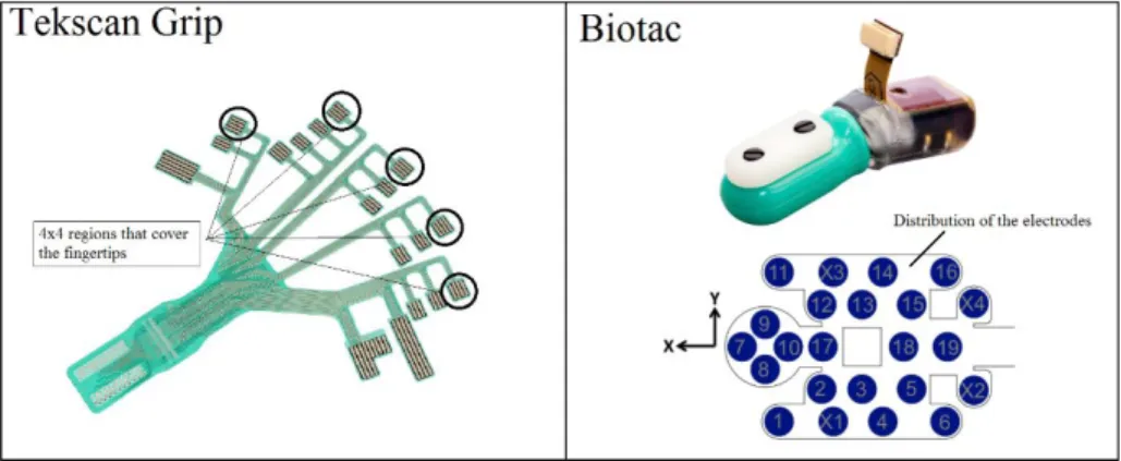
In this paper, we present a new approach which is mainly based on tactile information. Thus, the employed sensors are determinant components in the testing process. Two kinds of sensors were used to test the control strategy with different sensor technologies. One of them, Tekscan, is a hand-shaped tactile array used to read pressure, and the other one, Biotac, is a multifunctional tactile sensor which can obtain information about pressure, vibrations and temperature in contact points. The Tekscan sensor is composed by 18 regions that cover the fingers and the palm of the hand. Each region is composed by an array of tactels with different sizes. In the experiments, only the regions that cover the fingertips were considered. One of the motivations of the proposed framework is to define a common methodology that can be used with different kind of sensors. Usually, tactile sensors only cover the fingertip part of the hand (as the Biotac sensors). Fingertips are usually the parts which are used to hold and move the objects, so our framework is defined to consider the tactile information obtained from these parts, which correspond to the contact points. Tekscan sensors can obtain tactile information from the palm of the hand and/or the rest of the regions of the fingers, but this data is not used in this work. For the regions that are fixed to the fingertips, which are used in this paper, the number of tactels is 16, distributed in a 4x4 array in a region of 1.7 x 1.7 centimeters (see Figure 2). This sensor was previously calibrated to translate from raw pressure values to real pressure / force values. The response of this sensor is considered lineal in the range between 0 and 7 newtons of applied force.
The Biotac sensor is a multifunctional sensor that tries to imitate the human tactile sensing and it is capable of sensing pressure, vibration and temperature. The sensor consists in a rigid core, surrounded by an elastic liquid filled-skin to obtain a compliance similar to the human fingertip. To obtain measure of pressure the sensor uses impedance-sensing electrodes capable of measuring deformations that arise when normal or shear forces are applied to the surface of the sensor. The variation in the fluid changes the impedance of the electrodes, and these changes are measured as the output voltages to get raw pressure values. Besides, the sensor offers the possibility of measuring vibrations and temperature in the surface of the sensor. To detect vibrations a hydro-acoustic pressure transducer is used, while for the temperature, a thermistor is included in the sensor tip. In total, the sensor includes 19 electrodes distributed inside the sensing surface, and covering the different parts of the fingertip (see Figure 2).
Figure 2: Tekscan Grip sensor used in one hand, where the regions used in the fingertips are marked (left)(source:
Tekscan). Biotac sensor and scheme of the distribution of the 19 electrodes inside the sensor (right) (source Syntouch).
3
Tactile Image Creation Using a Mixture of Gaussians with Dynamic
Deviations
This section describes how a tactile image is created from source tactile values obtained from different sensors. A unique tactile image is created for each of the fingers of the robot hand, to get a map of the pressure that the hand can read on each contact point. Using tactile images instead of using sensor values directly has the advantage of having the tactile information in a unique format that can be used in different ways. First, a tactile image allows the detection of features of the contact, such as size and shape, using image processing techniques. Second, tactile images can be used to obtain points of contact, mean force, and mean force position. These features can be used to control the movements of the fingers and change the contacts’ configurations. This paper is focused on the second approach, but the presented technique based on tactile images can also be used for tactile image processing.
The goal of this method is to be independent of the sensor used to get tactile data. Only the positions of each of the tactels of the sensor and their values are needed. In this paper two different kinds of sensor were used, as described in Section 2: the Biotac sensor and the Tekscan sensor. One of the robotic hands, H1, has a Biotac sensor on each of the fingers. Each sensor contains 19 electrodes eiinside the physical
sensor. These electrodes are used as the original tactels tiused to create the tactile images Ii. In the case of
the hand with the Tekscan sensor, H2, only the sensor regions that correspond to the surface of the
fingertips were used. Each of this region is composed by 16 cells cidistributed in a 4x4 configuration.
These cells are used as the original tactels ti.
In the next subsections we present the stages that compose the technique for obtaining tactile images: first a projection of the tactels into a common finger surface is executed, then a value for deviation of the Gaussians that define the image is obtained dynamically using a nearest-neighbors strategy, and finally, the image is created with a mixture of Gaussians process (see Figure 3).
3.1 Projection of tactels’ values into a common finger surface
A common cylinder surface Siis defined to set as a base for each tactile image Iifor the fingersfiof the
two handsHi. This surface corresponds to the semi-cylinder that fits into the fingers of the robotic hand.
For the used Shadow hand, the size of the link that corresponds to the fingertip phalanx is known, and has a dimension for the equivalent semi-cylinder of a ratio of 7 millimeters and a height of 25 millimeters. The axis of this semi-cylinder is set as the Z axis of the tip frames O itip of the fingers fi. Using this
definition, the positions of the tactels tiof each activated tactile sensor are projected into the surface Siof
this semi-cylinder. The real 3D position of each tactel is given by the specifications of the product, and, in the case of the Tekscan sensor, the relative position using the tip frame as reference is measured after the sensor is attached to the hand. The point on the cylinder’s surface corresponding to each tactel is obtained using a radial projection. This point belongs to the radius vector that contains the tactel 3D point in reference to the tip frame and a point in the semi-cylinder’s central axis which has the same height value. The projected point is the cross point between the cylinder surface and this vector. Once the positions on the semi-cylinder are obtained, the 3D coordinates are converted into the equivalent coordinates on the planar surface PSi obtained from Si using a rectification of the curved surface. The plane surface
corresponds to the lateral surface of the semi-cylinder.
The plane has a fixed size, according to the size of the finger. To configure the definition of the image, the pixel size must be set. In this paper, the pixel size was set to a value of 2.5 millimeters. After initial experimentation, this size for the pixel is considered optimal to get a balance between the image size and resolution. Nevertheless, is a parameter that can be modified on-line to get more or less resolution and/or size of the tactile images.
Having the pixel size and image size, obtaining the number of pixels on the image is a trivial process. Then, having the number of pixels, image size, pixel size, and coordinates of each tactel on the surface, a direct conversion from plane coordinates for the tactels to pixel position on the image is carried out. The result of this part is the initial image Iiwhich only includes initial tactel values.
3.2 Obtaining dynamically the deviation of the Gaussians using the values of the k-nearest-neighbors
To obtain the values of the initial empty pixels of the tactile image that do not correspond to a tactel of the sensor, a regression technique based in Gaussian functions is used. The main idea of this process is to assign realistic values to the initial empty pixels p i,j, taking into account the values of the nearest
non-empty pixels of the image p*
i,j. A Gaussian functionGiis defined for each tacteltithat corresponds to
a non-empty pixel p*
i,j. The functions are defined in the next way: the position of the mean is set as the
position (x,y) of the pixel with initial value, the mean value is set as the normalized value of the corresponding pixel value, and the deviation for each function is set according to the k nearest neighbors’ values. We describe in this section how the deviation σivalue is set for each Gaussian G i. First, the initial
values of the tactels are normalized to a gray scale, corresponding 0 value to no pressure, and 255 to the maximum pressure value. The output range of the sensors’ response is employed to normalize the scale. The main idea of the normalization is to obtain a bounded pressure map independently of the format in which the source pressure data is obtained. In this paper, this method is used for a calibrated sensor (Tekscan sensor) and a non-calibrated sensor (Biotac sensor) to obtain the gray value v(ti) of the each
tactel :
- Tekscan sensor: the output values are represented as Newton values between 0N and 7N, which are obtained after the sensor was calibrated. The response has a resolution of 0.01N, so between 0N and 7N, there are 700 possible values.
- Biotac sensor: the sensor is used without a calibration into force values. The output of the sensor is a raw value that represents electrical impedance. The value 3300 corresponds to the lower value (no applied force) and 0 represents the higher value (maximum force). In this case, the resolution is 3300 values.
Next, the k nearest neighbors are obtained according to the distance in the image. The value of k is a variable that can be adjusted depending on the desired robustness/simplicity of the process. Low values of
k make the process more agile but less robust, while high values increase the robustness of the process but make it slower. In this paper, a value of 5 neighbors is used to get a balance between processing time and robustness. As a result, a vector containing the nearest neighbors for each tactel is obtained Nti= [n1, n 2,
n3, n4, n5]. The deviation σiof the Gaussian Giis the mean of the impact of each of the values of the
neighbors in Nti, as defined in Equation 1. The impact value is proportional to the value of the neighbor
v(nj) and a distance factor. The distance factor is set as a coefficient between the actual distance in pixels
from the neighbor (x,y) and the current tactel (x0, y0) associated to the Gaussian Gi, and the maximum
distance in pixels on the image. We remember that this distance in pixels depends on the pixel size that is set as an initial parameter.
σi= k [v(n ) ] ∑k j=1 j* d(t , n )i j max_distance (1)
In the two-dimensional plane defined for the tactile image, each Gaussian function is defined as follows, using the normalized value of the pixel v(ti):
(x, ) (t ) xp (− )) Gi y = v i * e ( 2σi2 (x−x )02+ 2σi2 (y−y )02 (2)
3.3 Applying a mixture of Gaussians technique to obtain the final complete tactile image
Once the values of the deviations are set, the mixture of Gaussians method is executed to obtain the tactile image GI. The final value of each pixel is set as the sum of all the Gaussian values on each position of the image (Equation 3).
I(x, )
G y = ∑Gi (3)
Applying this method, the regions of the image with more number of tactels with relevant values get more importance, while the regions with less number of tactels with relevant values are minimized. Figure 4 shows how different Gaussian images are created for different tactile values.
Figure 4: Different tactile images obtained with the mixture of Gaussians method for different contact configurations. From left to right: point contact on the finger end, central point contact, lineal contact on left side, and
point contact on the right side.
4
Tactile Servo Controller Based on Tactile Images
In this section the control technique is described in detail. The strategy controls the movement of the joints q˙fi(t) of each finger fiof the hands H ito get a desired tactile image I*. Using this method, the hand
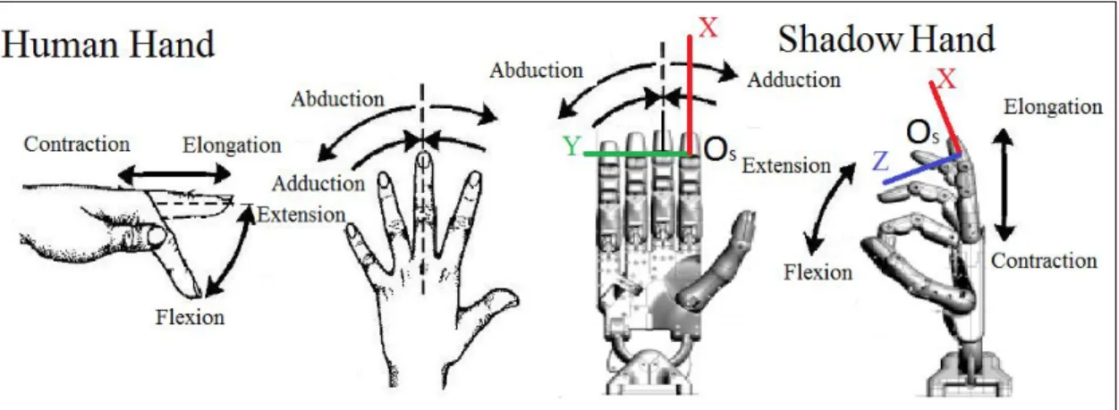
can be moved to obtain a desired global map of the forces applied, and to avoid sliding on each of the fingers. An independent controller is executed for each of the fingers of the hands, while an in-hand manipulation task is carried out. Figure 5 shows the different movements that can be controlled.
Figure 5: Finger movements: human hand and robot hand.
The controller is inspired on the human taxonomy to grasp and manipulate objects. As described in Section 2, the robot hand used to test the tactile framework is a humanoid hand, which facilitates the replication of human movements. These movements consider the synergies of the hand, so that each displacement on the finger implies the coordination of different articulations [31]. The fingers of the human hand can do extension-flexion and adduction-abduction movements. In the case of the thumb, the adduction-abduction movement is more complex, a palmar abduction movement and radial abduction is distinguished. Moreover, as it can be seen in Figure 5, we add a movement of contraction-elongation of the finger. The contracting movement moves the fingertip towards the palm of the hand, while the elongation separates it from the palm. All these human movements can be executed on the Shadow robot hand, so we present a control strategy in which, given a desired tactile image, the joints of the hand are moved to achieve this tactile configuration through these basic movements. The control architecture is described in the next paragraphs.
For each finger, we define the vector of features Sfi(t) = [S x, Sy, Sm ] ∈R to be tracked as the
3
position and magnitude of the resultant force in the tactile image, this is, the barycenter of the image. The image is considered in this technique as a planar surface, so the resultant force Smin the surface is
obtained as the sum of the pixel values pi,jof the image with size mxn, and the position is set as the mean
of the positions of the pixels.
Sm= ∑ m i=0∑ n j=0pi,j (4) Sx= Sm (p x ) ∑m i=0 ∑n j=0 i,j*i (5) Sy= Sm (p y ) ∑m i=0∑ n j=0 i,j* i (6)
For the desired image I*fi we define also the vector of desired features S (t) = [S*x, S* y, S*m ] .
*
fi ∈R
3
The error in the image is defined as the error between desired and current tactile features SΔ fi(t) = [ΔS x,
ΔSy, ΔSm] ∈R3: S (t) (t) (t) Δ f i = S * fi − Sfi (7)
Once the error vector is obtained, the components are translated from pixel values to millimeter values for the features Sx and Sy. The feature related to the magnitude is scaled from gray-scaled values to
millimeter values to define the finger displacement that is needed to correct the error in magnitude. This scaling process is not direct, different values for scaling the values can be used, so a parameter µ is created to modify the gain in the error. This parameter is used to translate pixel values (0 to 255, without
measure unit) to a measurable unit (millimeters). The goal of this translation is to get a homogeneous control signal (error in X, error in Y and magnitude, which corresponds to error in Z) which is later used on the PID controllers. In the experiments, this parameter was used with a fixed value, set to 0.05 after initial experimentation. As an example, if the desired force value translated to gray normalized value of the barycenter in the image is set to 150, and the current normalized value is 149, the error in pixel is translated into an error of 0.05 millimeters in position. If the error in normalized value was 100, the translated error in position will be 5 millimeters. With this scaling value, the system is stable and high velocities are avoided. The modification of the value of µ affects the velocity in which the fingers are moved depending on the output of the control loop. Depending on the coefficient of elasticity of the object which is manipulated, the value of µcan be set to high values for more rigid objects, or low values for more soft objects in order to avoid high deformations. The coefficient of elasticity is known or approximated with a recognition process [32]. How the scale affects the output may be considered similar to the configuration of a PID controller.
To correct the error in the tactile images with movements of each fi, we propose a two-stepped strategy
to get the desired hand movements. First, the error in the force is mapped to basic movements of the fingers: adduction-abduction, flexion-extension, contraction-elongation. These basic movements are considered in this approach as velocities in the sensor frame O S(fi) (see Figure 5). Then these basic finger
movements are mapped to joint movements q˙f(t) using the finger Jacobians . The next table
i JFfi
summarizes the proposed relationship between the error and the related movements in the hand to correct the error using the joints of the Shadow hand. The relationship between the velocities in the sensor frame OS(fi) is set according to the synergies of the fingers, and the movements are limited by the physical limits
of the joints:
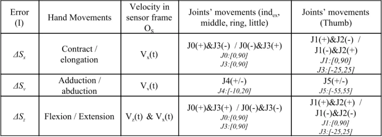
Table 1: Relationship between error in the image, related finger movements, velocities in the sensor frame OS, and joints. The number of each joint is set in order from the tip to the palm (J0 to J4, and J1 to J5 in the case of the
thumb).
Error
(I) Hand Movements
Velocity in sensor frame
OS
Joints’ movements (index,
middle, ring, little)
Joints’ movements (Thumb) ΔSx Contract / elongation Vx(t) J0(+)&J3(-) / J0(-)&J3(+) J0:[0,90] J3:[0,90] J1(+)&J2(-) / J1(-)&J2(+) J1:[0,90] J3:[-25,25] ΔSy Adduction / abduction Vy(t) J4:[-10,20] J4(+/-) J5:[-55,55] J5(+/-)
ΔSz Flexion / Extension Vz(t) & Vx(t)
J0(+)&J3(+) / J0(-)&J3(-) J0:[0,90] J3:[0,90] J1(+)&J2(+) / J1(-)&J2(-) J1:[0,90] J3:[-25,25]
As a result, we obtain a tactile interaction matrix T that relates the tactile error into finger velocities using the sensor frame OS(fi) as reference frame vfi(t). Finally, the finger Jacobian JFfi is used to map
the finger movements into joint movements depending on the robot hand used. In our case, the movements are mapped into joint movements as it is shown in table 1. To imitate the human behavior, a coupled movement of the joints 0 and 3 is considered in the contraction-elongation and flexion-extension movements (see Equations 8, 9 and 10).
{1 0 1 0 1 0 0 0 µ } T−1= (8) (t) T · (K · ΔS (t) ·K S (t)dt ·K (ΔS (t) ΔS (t ))) vf i = −1 p fi + i
∫
Δ fi + d fi − fi − 1 (9) (t) (t) q˙f i = JFfi * vfi (10)The output joint velocities are integrated each loop interval to get the new joint positions qf(t)
i
to correct the error. Besides, in the control architecture a direct control of the joints is considered to allow finger gaiting, when changes on the contact position are required. The commands related with the changes in contact configuration have higher priority than the tactile reconfiguration.
Figure 6 shows the diagram of the control architecture. The different steps are described below.
Figure 6: Control diagram of the servo-tactile architecture executed on each finger fi.
5
Experimental Results and Discussion
This section shows different experiments performed to test the presented tactile framework. Two kinds of experiments were carried out: experiments involving only one finger, and experiments involving movements of the both robot arms and hands. The first set of experiments was used to analyze the response in the controller to keep the contact between one finger and an object. The second set of experiments was used to test the response of the controllers executing in a simultaneous way to keep contacts while the hands hold objects, and the arms are moved to produce deformations on that object.
The optimal value for the number of the k-nearest neighbors used to create the tactile images was set after initial experimentation, in which the obtained tactile images were compared using different values for the neighbors. The value of k was set to 5, because is a value which allows the framework to obtain an image where the contact area is well defined. Higher values could be used to get more precise images, but using more number of neighbors requires higher computational time, and this makes the system slower.
The real experiments were not conducted on a real time environment, so the iteration time is not constant. The time of a cycle of response from the controller is limited by the frequency of response of the sensor, 1 millisecond for the Tekscan sensor, and the processing time in a normal multi-task CPU. The iteration time is higher for the experiments which involve the use of the two hands, because in total, 10 processing threads are executed in parallel to get the tactile image and velocities for each of the fingers. The motivation of this work was to analyze the controller in terms of convergence rather than velocity. Nevertheless, in the experiments the time of a cycle was lower than 10 milliseconds for a single execution of a controller and 100 milliseconds for the execution in parallel of the 10 servo-tactile controllers. In addition, we also provide several videos of the experiments in order to facilitate the understanding of the system.
5.1 Single-finger tactile control
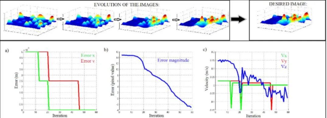
The next experiments show how the tactile-servo controller is used with one finger to maintain a configured contact with an object or surface for both sensors. The desired images are obtained with previous experimentation in which the fingers are moved manually until a desired force is obtained, and the corresponding image is generated. The first experiment described, shows how the tactile-servo controller reacts in a situation in which the contact position is wanted to be moved to the fingertip, and with a certain value of magnitude. For this experiment a contact generated by a human finger is used, and different reactions are tested (see Figure 7). Figure 8 shows how the tactile images evolve, the desired image, and the changes in the error and output velocities. In the case of the error in position it can be seen
how the difference between the target value and current value of the mean position is corrected by the output velocities. Regarding the error in the magnitude of the force, the output velocities produce a reduction in the error. In this experiment, the human finger is separated manually to test the response of the controller. It can be seen that the error converges to zero after each variation in the contact.
Figure 7: Experiment with the servo-tactile control, different steps. Controlling the magnitude of the force in the
contact.
Figure 8: Evolution of error (a, b), velocities (c) and sample and desired tactile images (above).
In the previous experiment, the target image was related to a precise contact point in the fingertip of the finger. In the next experiment, we show how the controller can be used also to obtain regions of contact in the finger, correcting the error in position and magnitude of the mean force (see Figure 9). As it can be seen in Figure 10, the target image represents a configuration in which the contact with the object covers almost all the right side of the finger. Initially, the finger is touching the object, but not applying force. Next figure shows how the error in positions and magnitude are corrected with the output velocities. Different samples of the tactile images in different steps are included to illustrate how the error is corrected and the output velocities converge to values close to zero (see video 1 for the complete experiments).
Figure 9: Experiment with the servo-tactile control. Controlling magnitude and position of the force in the contact.
Figure 10: Evolution of the error (a, b), velocities (c) and sample and desired tactile images (above).
As it can be seen on Figure 8 and Figure 10, the force position error and the output velocities converge to zero. Regarding the error in force magnitude, and the Vzcomponent, the convergence is not perfect
(zero value is not stable), because it is affected by the signal drifting that is inherent for all the tactile sensors. The value obtained from the sensors is not stable even if the contact configuration does not vary.. Nevertheless, it can be analyzed how the controller reacts, and the velocities and errors evolve to values proximal to zero, with low variation produced by this signal drifting. The variations in the output velocities are related directly with the variations of the forces sensed by the tactile sensor. Paying attention to the scale in the velocities graphics, it can be seen that peaks on those graphics represent a notable change in the contact point which is corrected by the controller. Lower peaks are caused by the signal drifting from the tactile sensor, which is inherent to the electric response of the devices. Nevertheless, this chattering in the output velocities caused by the tactile sensor signal drifting, is not relevant to cause unexpected behavior in the controllers (notice the scale for the lower peaks in the velocity graphics).
5.2 Dual hand collaboration with multi-finger tactile control
The next experiments show how the servo-tactile controllers are executed in parallel for each finger of the hands to control the configuration of the contacts while a collaboration task is executed moving both arms. The next kind of collaborations were considered: bending a soft beam, folding a planar foam, and throwing material from a bag into a recipient. Considering all kind of collaboration tasks that can be executed with a bimanual system, these three experiments were selected because in the three cases the movements of the arms to execute the actions produce variations in the contact configuration for each hand. Considering that the proposed framework does not use a model of the object/s, the tactile-servo technique is proposed to be used as a low level control strategy to maintain contacts, while at higher level, arms are moved in a planned way to produce the desired deformations or changes in volume and/or shape in the objects. We start at an initial valid configuration in which the objects are correctly grasped, and then, simplified movements of the arms considering the end effector position are executed. For the bending experiment, two opposite rotational movements are executed to produce the deformation in the object. In the case of the folding task, the end effector of each arm is moved in the same plane, but in opposite side. Finally, for the experiment in which some material is thrown from a plastic bag into a recipient, a unique rotational movement of the end effector of the arm that holds the bag is executed to imitate the human behavior to carry out this kind of task.
The servo tactile controller is defined to correct the error in both features to obtain the desired configuration. Desired magnitude and positions are variable features that can be adjusted depending on the task to be carried out. In these experiments, for each finger, the target force and magnitude are set in the next way:
- Contact position: the desired contact position is set into the center of the fingertip to maximize contact area. Using the tactile information obtained from the whole sensor area, the tactile image is obtained, and then the barycenter of the image is used as the reference point to be tracked and maintained in the center of the image, which is the physical center of the sensor area. Using the center of the fingertip as the desired position makes more difficult a loss of contact on the finger.
- Force magnitude: regarding the magnitude, the force values were taught to the system on an initial teaching stage. In this stage, the applied forces were tracked and studied performing grasping experiments using the same objects used later to test the framework. Each of the objects was grasped in a tele-operated way until a secure grasp was obtained. Then, the applied forces in this secure configuration are obtained and used later as target values for the servo-tactile control.
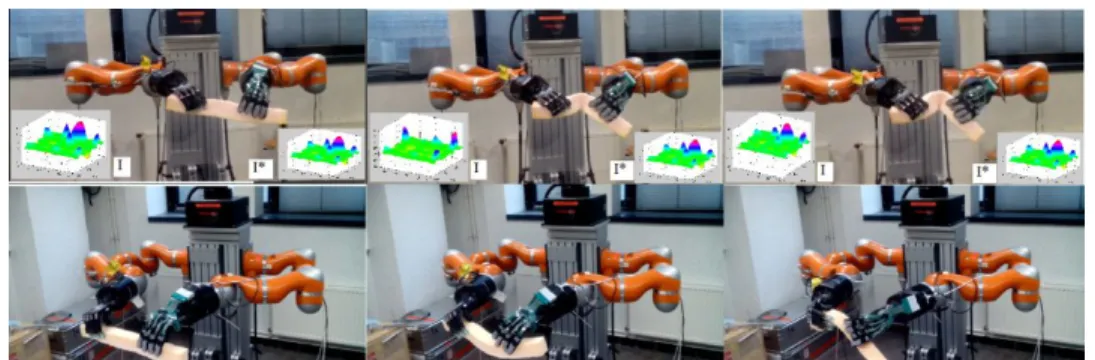
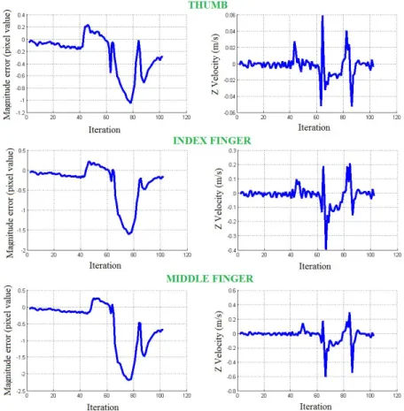
For the first experiment a soft beam is considered. The foam is hold by the 10 fingers of the two Shadow hands, and a servo-tactile controller is executed for each of the fingers. Initial force is set as the target force to maintain during the experiment to avoid the loss of contact, and as a result the drop of the object. An example of the behavior of the controller for three of the fingers (thumb, index and middle, which are the dominant fingers in a grasp or manipulation task) can be seen in Figure 12. The graphics show the evolution of the error in the target force (magnitude), related to the rotation of the wrist of the arm, and the graphics of velocities show the output velocities set by the controller. It can be appreciated how the controller reacts to different variations in the contacts to minimize the error. Figure 11 shows the comparison in the execution of the same experiment using the tactile control and without executing the servo-tactile controller. The controller helps to maintain the contact with the object and prevent it to drop after sliding starts (see video 2).
Figure 11: Bending experiment with servo-tactile control (up) and without servo-tactile control in the fingers (down). For the execution with the servo-tactile control, a sample tactile image (I) is shown (in this case for the index
Figure 12: Evolution of the error in force magnitude and output Z velocities for three of the fingers during the bending task.
For the second experiment, a process is executed to fold a planar foam applying forces through lineal movements of the two arms while the attached hands hold the body for each side. Without executing the servo control, the deformation of the object cause an external variation in the contacts, and this produces a loss of contact. Applying our technique, the target forces are maintained during the task, and the loss of contact is avoided. Figure 14 shows the evolution of the error in force and the output velocities for three fingers. The final part of the graphics correspond to the step in which the foam is totally folded. Despite the error is not corrected completely, the servo-tactile control reacts to move the finger and to keep the error value at a low value to prevent sliding. In Figure 13 it can be seen how after the object has been folded, without using the servo-tactile control the contact is lost in one of the hands, and when the object is unfolded, it drops from the hand. With the proposed control technique, even if the error is not completely corrected, the contact is maintained and the sliding and consequently the drop of the object is avoided (see video 3).
Figure 13: Bending experiment with servo-tactile control (up) and without servo-tactile control (down). For the
execution with the servo-tactile control, a sample tactile image I is shown (in this case for the index finger). The desired configuration is shown in the image I*.
Figure 14: Evolution of the error in force magnitude and output Z velocities of the controllers for three fingers during the folding experiment.
The third kind of task that is presented in this paper, is a task which includes a collaboration between the two systems arm-hand holding two objects. In this task a bag of pasta is hold by one of the hands, and a container is hold by the other hand. The task consists in dropping pasta in the container. For this kind of tasks, a model of the object is very difficult to obtain, because the shape and weight of the bag depends on the number of elements that remain inside, and the variation in this amount is unpredictable, and depends on a lot of factors (velocity for the arm, positions on the finger, size of the contained elements). In the case of the container the shape does not change, but the weight changes accordingly to the number of elements that drop inside. This change in the weight, could produce sliding in the contact points, and eventually make the container fall down. Considering this complexity to model and control the task, an agile and adaptable technique is needed. In this experiment we demonstrate that the proposed tactile-servo framework can be used for this kind of tasks. The experiment is executed with one hand holding the container in a fixed position, and the other hand holding the bag in a position above the container. To throw the pasta into the container a basic rotational movement of the wrist of the arm is executed, as a human moves his wrist, to start the dropping process. Taking into account that counting and controlling the frequency of elements that are dropped into the container is a non-controllable issue, the tactile-servo controllers are executed for each of the fingers of the hands, to keep the contact position and magnitude while the process is carried out. Whereas the task fails when is executed without adaptation in the finger positions, using the presented technique, the task is executed correctly (see Figure 15 and video 4). In Figure 16 it can be seen how a big variation in the target features (force magnitude) appears for the fingers that hold the bag in the same instant, when the pasta begins to drop. The controllers react to avoid this big variations, produced by the changes in volume and weight of the bag, and the error is minimized to avoid the loss of contact.
Figure 15: Collaboration experiment using servo-tactile control (up) and without servo-tactile control (down). For
the execution with the servo-tactile control, a sample tactile image I is shown (in this case for the index finger). The desired configuration is shown in the image I*.
As it was explained in the Section 5.1, the convergence of the error in force magnitude, and the Vz
component is not perfect because of the signal drifting inherent for all the tactile sensors. Nevertheless, this imprecision is not relevant to affect the stability of the contact configuration. The output velocities for each controller keep the finger in a position that maximizes the contact area, minimizing the error in contact position, and move the finger to reach the target magnitude value. As in the single-finger experiments, peaks on the velocity graphics represent a notable change in the contact point which is corrected by the controller, and lower peaks are caused by the signal drifting from the tactile sensor, which is inherent to the electric response of the devices.
Figure 16: Evolution of the error in force magnitude and output Z velocities of the controllers of three of the fingers during the collaboration experiment.
6
Conclusions
In this paper, a new framework to track the fingers’ contacts between a robot hand and an object and to control the movements of the fingers according to this tactile sensation is proposed. The main motivation of this work was to develop an agile and adaptable system that could be used in manipulation tasks with different hardware equipment (robot hands and tactile sensors). In this paper, it has been demonstrated that the proposed framework can be used as part of an in-hand manipulation controller, to maintain and adapt the contact configuration depending on the tactile configuration that is required. Besides the adaptability, the second big advantage of the proposed methodology is that it can work without models of the objects that are manipulated. As it has been explained in previous sections, having a manipulation methodology that depends on models of the objects, makes the system less useful when the robot is wanted to be operative in variable environments with a huge variety of objects that the robot has to grasp and manipulate.
The proposed representation for tactile data, is one of the principal contributions of this paper. The presented method, based on a combination of dynamic Gaussians that are defined from the sensor values, offers a novel way to represent and use tactile information. This method can be used with any tactile sensor for which physical properties are known, so, as presented in this paper, the framework is adaptable to different robot and sensor systems.
As future work, a global planner is proposed to control the movements of a complete system composed by arm, hand, tactile sensor and vision sensor. The idea of this global planner is to predict deformations and create trajectories on the arms and hands to carry out manipulation tasks. The global planner could use the proposed framework as a lower lever control structure, to track the contacts’ configuration and the movements of the fingers to adapt the applied forces and avoid sliding or other loss of contact caused by external forces.
Acknowledgements
.
Research supported by the Spanish Ministry of Economy, European FEDER funds, Valencia Regional Government and University of Alicante through the projects DPI2015-68087-R, PROMETEO/2013/085 and GRE 15-05. This work has been also supported by the French Government Research Program Investissements d’Avenir, through the RobotEx Equipment of Excellence (ANR-10-EQPX-44) and the IMobS3 Laboratory of Excellence (ANR-10-LABX-16-01).References
[1] Bicchi, A. & Kumar, V. (2000), Robotic Grasping and Contact: A Review, Proc. IEEE Int. Conf. On Robotics and Automation, pp. 348-353.
[2] Baeten, J. & De Schutter, J. (2003). Integrated Visual Servoing and Force Control - The Task Frame Approach, Springer Tracts in Advanced Robotics, Vol. 8, B. Siciliano, O. Khatib, and F. Groen, (Eds.), Springer, Berlin.
[3] Deng, L.; Janabi-Sharifi, F. & Hassanzadeh, I. (2005). Comparison of Combined Vision/Force Control Strategies for Robot Manipulators, Proc. of SPIE Int. Symp. Optomechatronic Technologies: Optomechatronic Systems Control Conference, pp 1-12.
[4] Allen, P. K.; Miller, A. T., Oh, P. Y. & Leibowit z, B. S. (1999). Integration of Vision, Force and Tactile Sensing for Grasping, Int. J. of Intelligent Machines, Vol. 4, pp. 129-149.
[5] Jiménez, P. (2012). Survey on model-based manipulation planning of deformable objects. Robotics and Computer-Integrated Manufacturing, 28(2), 154-163.
[6] Cretu, A. M., Payeur, P., & Petriu, E. M. (2012). Soft object deformation monitoring and learning for model-based robotic hand manipulation. IEEE Transactions on Systems, Man, and Cybernetics, Part B: Cybernetics, 42(3), 740-753.
[7] Berenson, D. (2013). Manipulation of deformable objects without modeling and simulating deformation. IEEE International Conference on Intelligent Robots and Systems (pp. 4525-4532). [8] Khalil, F. F., Payeur, P., & Cretu, A.-M. (2010). Integrated multisensory robotic hand system for
deformable object manipulation. Proceedings of the IASTED International Conference on Robotics and Applications (pp. 159-166).
[9] Wada, T. ; Hirai, S., Kawamura, S. & Kamiji, N. (2001). Robust Manipulation of Deformable Objects by a Simple PID Feedback, Proc. IEEE Int. Conf. on Robotics and Automation, pp.85-90.
[10] Foresti, G. L. & Pellegrino, F. A. (2004). Automatic Visual Recognition of Deformable Objects for Grasping and Manipulation, IEEE Trans. on Systems, Man, and Cybernetics: Applications and Reviews, Vol. 34, pp. 325-333.
[11] Luo, S., Mou, W., Althoefer, K., & Liu, H. (2015). Localizing the Object Contact through Matching Tactile Features with Visual Map. IEEE Conference on Robotics and Automation (ICRA), 2015-June, 3903 - 3908.
[12] Li, Y. & Kao, I. (2001). A Review of Modeling of Soft-contact Fingers and Stiffness Control for Dexterous Manipulation in Robotics, Proc. IEEE Int. Conf. on Robotics and Automation , pp. 3055-3060.
[13] Lee, A. X., Lu, H., Gupta, A., Levine, S., & Abbeel, P. (2015). Learning force-based manipulation of deformable objects from multiple demonstrations. Proceedings - IEEE International Conference on Robotics and Automation(Vol. 2015, pp. 177-184). Institute of Electrical and Electronics Engineers Inc.
[14] Lee, A. X., Gupta, A., Lu, H., Levine, S., & Abbeel, P. (2015). Learning from multiple demonstrations using trajectory-aware non-rigid registration with applications to deformable object
manipulation. IEEE International Conference on Intelligent Robots and Systems (Vol. 2015, pp. 5265-5272). Institute of Electrical and Electronics Engineers Inc.
[15] Boonvisut, P., & Cavusoglu, M. C. (2014). Identification and active exploration of deformable object boundary constraints through robotic manipulation. The International Journal of Robotics Research, 33(11), 1446-1461.
[16] Li, Y., Chen, C. F., & Allen, P. K. (2014). Recognition of deformable object category and pose. Proceedings - IEEE International Conference on Robotics and Automation (pp. 5558-5564). Institute of Electrical and Electronics Engineers Inc.
[17] Kappassov, Z., Corrales, J. A., & Perdereau, V. (2015). Tactile sensing in dexterous robot hands - Review. Robotics and Autonomous Systems, 74, 195-220. Elsevier.
[18] Tiwana, M. I., Redmond, S. J., & Lovell, N. H. (2012). A review of tactile sensing technologies with applications in biomedical engineering. Sensors and Actuators, A: Physical, 179, 17-31.
[19] Dahiya, R. S., Metta, G., Valle, M., & Sandini, G. (2010). Tactile Sensing - From Humans to Humanoids. IEEE Transactions on Robotics, 26(1), 1-20.
[20] Chen, N. N., Zhang, H. Z. H., & Rink, R. E. (1997). Touch-driven robot control using a tactile Jacobian. Proceedings of International Conference on Robotics and Automation, 2(April), 1737-1742. [21] Li, Q., Sch, C., Haschke, R., & Ritter, H. (2013). A control framework for tactile servoing. Rss201. [22] Romano, J. M., Hsiao, K., Niemeyer, G., Chitta, S., & Kuchenbecker, K. J. (2011). Human-inspired
robotic grasp control with tactile sensing. IEEE Transactions on Robotics, 27(6), 1067-1079.
[23] Tsutsui, H., Murashima, Y., Honma, N., & Akazawa, K. (2013). Robot hand with soft tactile sensors and underactuated control. Proceedings of the Annual International Conference of the IEEE Engineering in Medicine and Biology Society, EMBS (pp. 4148-4151).
[24] Yuan, W., Li, R., Srinivasan, M. A., & Adelson, E. H. (2015). Measurement of shear and slip with a GelSight tactile sensor. 2015 IEEE International Conference on Robotics and Automation (ICRA) (Vol. 2015, pp. 304-311).
[25] Luo Y. & Nelson, B. J. (2001). Fusing Force and Vision Feedback for Manipulating Deformable Objects, J. of Robotic Systems, Vol. 18, pp. 103-117.
[26] Smith, C., Karayiannidis, Y., Nalpantidis, L., Gratal, X., Qi, P., Dimarogonas, D., Kragic, D. (2012). Dual arm manipulation—A survey, Robotics and Autonomous Systems, Volume 60, Issue 10, October 2012, Pages 1340-1353, ISSN 0921-8890, http://dx.doi.org/10.1016/j.robot.2012.07.005. [27] Kuka LWR robot. [Online]. Available:
http://www.kuka-robotics.com/en/products/industrial_robots/sensitiv/start.htm [28] Shadow Robot, “Dexterous Hand”. [Online]. Available:
http://www.shadowrobot.com/products/dexterous-hand/.
[29] Syntouch BioTac, tactile sensor. [Online]. Available: http://www.syntouchllc.com/Products/BioTac/. [30] Tactile Sensor Tekscan. [Online]. Available: http://www.tekscan.com/grip-pressure-measurement. [31] Marco Santello et al. Towards a synergy framework across neuroscience and robotics: Lessons
learned and open questions. Reply to comments on: “Hand synergies: Integration of robotics and neuroscience for understanding the control of biological and artificial hands”, Physics of Life Reviews, Volume 17, July 2016, Pages 54-60, ISSN 1571-0645.
[32] Delgado, A.; Jara, C.A.; Mira, D. and Torres, F. (2015). A tactile-based grasping strategy for deformable objects' manipulation and deformability estimation. Informatics in Control, Automation and Robotics (ICINCO), 2015 12th International Conference on, Colmar, 2015, pp. 369-374.