Publisher’s version / Version de l'éditeur:
Vous avez des questions? Nous pouvons vous aider. Pour communiquer directement avec un auteur, consultez la
première page de la revue dans laquelle son article a été publié afin de trouver ses coordonnées. Si vous n’arrivez pas à les repérer, communiquez avec nous à [email protected].
Questions? Contact the NRC Publications Archive team at
[email protected]. If you wish to email the authors directly, please see the first page of the publication for their contact information.
https://publications-cnrc.canada.ca/fra/droits
L’accès à ce site Web et l’utilisation de son contenu sont assujettis aux conditions présentées dans le site LISEZ CES CONDITIONS ATTENTIVEMENT AVANT D’UTILISER CE SITE WEB.
Interflam 2007: Proceedings of the 11th International Conference on Fire Science
and Engineering, pp. 979-991, 2007-09-03
READ THESE TERMS AND CONDITIONS CAREFULLY BEFORE USING THIS WEBSITE. https://nrc-publications.canada.ca/eng/copyright
NRC Publications Archive Record / Notice des Archives des publications du CNRC : https://nrc-publications.canada.ca/eng/view/object/?id=f5537c4c-2095-49ab-8065-efa2c117ba21 https://publications-cnrc.canada.ca/fra/voir/objet/?id=f5537c4c-2095-49ab-8065-efa2c117ba21
NRC Publications Archive
Archives des publications du CNRC
This publication could be one of several versions: author’s original, accepted manuscript or the publisher’s version. / La version de cette publication peut être l’une des suivantes : la version prépublication de l’auteur, la version acceptée du manuscrit ou la version de l’éditeur.
Access and use of this website and the material on it are subject to the Terms and Conditions set forth at
Gypsum board fall-off temperature in floor assemblies exposed to
standard fires
http://irc.nrc-cnrc.gc.ca
G y p s u m b o a r d f a l l - o f f t e m p e r a t u r e i n f l o o r
a s s e m b l i e s e x p o s e d t o s t a n d a r d f i r e s
N R C C - 4 9 2 4 0
S u l t a n , M . A . ; R o y - P o i r i e r , A .
A version of this document is published in / Une version de ce document se trouve dans: 11th International Fire Science & Engineering Conference, London, UK., Sept. 3-5, 2007, pp. 979-991
The material in this document is covered by the provisions of the Copyright Act, by Canadian laws, policies, regulations and international agreements. Such provisions serve to identify the information source and, in specific instances, to prohibit reproduction of materials without written permission. For more information visit http://laws.justice.gc.ca/en/showtdm/cs/C-42
Les renseignements dans ce document sont protégés par la Loi sur le droit d'auteur, par les lois, les politiques et les règlements du Canada et des accords internationaux. Ces dispositions permettent d'identifier la source de l'information et, dans certains cas, d'interdire la copie de documents sans permission écrite. Pour obtenir de plus amples renseignements : http://lois.justice.gc.ca/fr/showtdm/cs/C-42
GYPSUM BOARD FALL-OFF TEMPERATURE IN
FLOOR ASSEMBLIES EXPOSED TO STANDARD
FIRES
Mohamed A. Sultan* & Audrey Roy-Poirier† Fire Research Program
Institute for Research in Construction National Research Council of Canada
Ottawa, Ontario, Canada
ABSTRACT
Major research efforts are being invested into developing numerical models that can be used by designers to predict the fire resistance performance of lightweight framed assemblies and to reduce the need for conducting standard fire resistance tests, which are both costly and time consuming. One important limitation of the existing models developed for this purpose is the prediction of gypsum board fall-off, which significantly impacts the fire resistance of an assembly. This paper presents and discusses the results of attempts that were made to develop temperature criteria for the gypsum board layers fall-off in floor assemblies tested under standard fire conditions.
Results from eighty full-scale standard fire tests on lightweight frame floor assemblies, protected with either one or two layers of Type X gypsum board, were classified in eight categories based on various parameters affecting the fire performance of gypsum board. Temperature recordings at the various gypsum interfaces in the assemblies were used to approximate the temperature of the gypsum board layers at fall-off using four different approaches. The first approach was based on the average temperature recorded at the time of fall-off, during fire resistance tests, of the first piece and at the time of fall-off of the last piece of each gypsum board layer. The second approach used the average of the first and last piece fall-off temperature criteria determined in the first approach. The gypsum board temperature at the time corresponding to the average of the first and last piece fall-off times was used to estimate the average fall-off temperature in the third attempt. The last method dealt with individual temperature histories and looked at the sudden increase in temperature caused by gypsum board fall-off.
INTRODUCTION
With the advent of performance-based codes and performance-based fire safety design options, the development of fire resistance models becomes an important tool to aid their implementation. Currently, major fire safety research efforts are being invested globally into developing numerical models that can be used by designers to facilitate the move to performance-based options. Development of such models faces several challenges such as the availability of reliable thermal and mechanical properties of materials, as well as information on the performance of building materials at elevated temperatures.
*
Senior researcher and Group Leader of the Fire Resistance and Risk Management subprogram
†
In lightweight frame construction, one important limitation of the existing models is the prediction of gypsum board fall-off, which significantly impacts the prediction of fire resistance of an assembly. Studies 1,2 showed that, in lightweight frame assemblies, gypsum board provides up to 90% of fire resistance protection, owing in the major part to its high water content.
Fire resistance models typically consist of a thermal model and a structural model. The thermal model calculates the temperature history of the assembly’s components and feeds those temperatures to the structural model for determining the thermal and structural properties at a given time, which are used for calculating the response of the assembly. To calculate the temperature history, it is essential to determine how long the gypsum board ceiling will stay in place to protect the assembly’s frame. This can be defined either by the observed time of gypsum board fall-off or, alternatively, by the temperature at which the gypsum board will likely fall-off when exposed to heat. Due to the difficulty in predicting gypsum board fall-off times for assemblies with configurations that have not previously been tested, a time failure criterion is impractical for use in numerical modelling. The purpose of this study is to establish a temperature criterion for the gypsum board fall-off that can be used to improve the accuracy of fire resistance models for lightweight floor assemblies.
The National Research Council’s Institute for Research in Construction (NRC-IRC), in collaboration with industry and government partners, has carried out two major experimental research studies (Floors-I1 and Floors-II2) to measure the fire resistance and acoustic performance of full-scale floor assemblies with different framing types. Details on the assemblies’ construction and fire resistance results of these studies can be found in References 1 and 2. A study3 on gypsum board fall-off time was also carried out jointly between NRC-IRC and Carleton University. Gypsum board fall-off times were determined from test observations and video-recordings of the fire-exposed gypsum board surfaces in a furnace operating with premixed flame. That study highlighted gypsum board fall-off times vary considerably from one assembly to the other depending on the materials and configuration selected. More details on that study and its findings are in Reference 3.
Gypsum Board
Gypsum board provides significant fire resistance protection to building assemblies. It is found in the form of a sheet product that consists of a non-combustible core pounded with paper-laminated surfaces, which is at least 75% pure gypsum and 25% additives such as glass fibre and vermiculite as well as other materials to enhance the fire resistance performance by reducing the likelihood of crack propagations and board shrinkage when exposed to heat. The gypsum core is calcium sulphate dehydrate, CaSO4 .2H2 O, a crystalline mineral that contains
about 21% by weight of chemically combined water. In addition, gypsum usually contains a small amount of absorbed free water. As the gypsum is heated to a temperature in excess of 80°C, it begins to undergo a thermal degradation process known as calcinations, in which the chemically combined water dissociates from the crystal lattice. The chemical equation for this process is:
CaSO4 .2H O2 → CaSO4 ½ H2 O + 3/2 H2 O [1]
Calcium sulphate hemihydrate (CaSO4 ½ H2 O + 3/2 H2 O) is commonly known as plaster of
Paris. As the gypsum core reaches 125°C, calcinations are usually complete. Through continued heating, the remaining water is released as the hemihydrate undergoes dehydration to form anhydrous calcium sulphate (CaSO4).
DESCRIPTION OF TESTS Test Assemblies
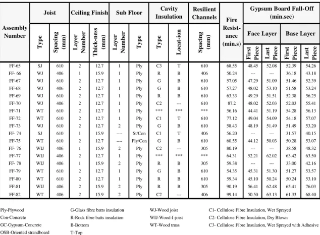
Eighty floor assemblies, 4.8 m long by 3.9 m wide, were constructed in accordance with CAN/CSA-A82.31-M914 to investigate the effect of different parameters on the fire resistance performance of floor assemblies consisted of solid wood, wood I- joists, steel C- joists and wood trusses. In 72 floor assemblies (see Table 1) resilient channels, spaced either 203 mm o.c. or 406 mm o.c., or 610 mm o.c., were used for sound reduction purposes and attached perpendicular to either the joists or trusses to support the gypsum board ceiling finish. Additional resilient channels were also installed to support gypsum board ends (board short dimension). The resilient channels, 14 mm deep by 58 mm wide, were fabricated from 0.6 mm thick galvanized steel sheets. The channels had a 34 mm wide web, designed to support the gypsum board connection, and one 18 mm wide flattened flange lip connected to the bottom of the joists or trusses. Three types of insulation were used: glass and rock fibre batts, and cellulose fibre insulation either sprayed wet on the underside of the sub-floor and on the side of the joists and allowed to dry to achieve an 11% moisture content or dry blown and supported at the bottom of the joists or trusses with a steel mesh. The glass, rock and cellulose insulation satisfied CSA A101-M835, CAN/ULC S702-M976 and CGSB 51.60-M907, respectively. The sub-floor types used in the assemblies were either Canadian Softwood Plywood (CSP) or steel deck with concrete topping. The ceiling finish used in the assemblies was Type X gypsum board, 12.7 mm and 15.9 mm thick, and had Firecode C designation and met the requirements of Type X gypsum board8,9. The gypsum boards had an average surface density of 9.85 kg/m2 for a nominal 12.7 mm thick board and 10.5 kg/m2 for a nominal 15.9 mm thick board. They were attached perpendicular either to resilient channels in 72 assemblies or directly to the framing in 8 assemblies. Table 1 summarizes the main variable parameters of the assemblies studied. Complete construction details can be found in References 1 and 2.
Instrumentation
In addition to the standard instrumentation specified in CAN/ULC-S101-M8910, numerous thermocouples (over 100) were placed within each floor assembly in order to obtain temperature histories at various locations during fire tests for further use beyond the scope of the above-mentioned studies. Type K (20 gauge) chromel-alumel thermocouples, with a thickness of 0.91 mm, were used for measuring the temperatures of the sub-floor surface and gypsum board surface facing the floor cavity as well as the interface surface between the gypsum board for assemblies with two layers of gypsum board and between the gypsum board and insulation at the floor cavity side. Temperature readings were recorded every minute across the floor assemblies. Details on the locations of the thermocouples can be found in References 1 and 2. All floor assemblies were tested with a superimposed load depending on the components of the assembly. Assemblies FF-01A to FF-09 were tested using a restricted load of 75% of maximum design load; while assemblies FF-10 to FF-82 were tested on a maximum design load. Two video cameras were used to record the fire-exposed gypsum board performance.
Test Conditions and Procedures
The assembly’s gypsum board ceiling finish was exposed to heat in a propane-fired horizontal furnace in accordance with CAN/ULC-S101-M8910, “Standard Methods of Fire Endurance Tests of Building Construction and Materials”. The furnace temperature was measured by nine (20 gauge) shielded thermocouples and the average of these thermocouples was used to control the furnace temperature in such a way that it followed, as closely as possible, the CAN/ULC-S101-M89 standard temperature-time curve.
Table 1: Summary of Fire Resistance Test on Floor Assemblies Results Resilient Channels Fi r st Pi e c e La st Pi e c e Fi r st Pi e c e La st Pi e c e FF-01A WJ 406 1 12.7 1 Ply *** *** *** 30 --- --- 24.22 31.20 FF-02A WJ 406 1 12.7 1 Ply *** *** 406 45 --- --- 42.07 47.20 FF-03A WJ 406 2 12.7 1 Ply *** *** 406 80 49.42 57.30 77.43 82.20 FF-04A WJ 406 2 12.7 1 Ply R B 406 72 48.19 53.15 56.50 63.43 FF-06 WJ 406 2 12.7 1 Ply G B 406 67 44.43 48.50 57.30 62.45 FF-07 WJ 406 1 12.7 1 Ply C1 T 406 59 --- --- 34.00 38.22 FF-08 WJ 406 1 12.7 1 Ply G B 406 36 --- --- 26.14 31.00 FF-09 WJ 406 1 12.7 1 Ply R B 406 60 --- --- 26.35 32.11 FF-10 WIJ 406 2 12.7 1 Ply *** *** 406 69 47.53 57.59 68.36 70.45 FF-11 WIJ 406 2 12.7 1 Ply *** *** 406 74 49.47 65.15 73.46 76.45 FF-12 WIJ 406 2 12.7 1 Ply *** *** 406 80 54.24 62.43 78.55 82.25 FF-13 WIJ 406 2 12.7 1 Ply *** *** 406 72 56.06 70.00 69.18 74.20 FF-14 WIJ 406 1 12.7 1 Ply *** *** 406 42 --- --- 40.53 44.00 FF-15 WIJ 406 2 12.7 1 Ply G B 406 64 53.16 59.33 56.50 66.00 FF-16 WIJ 406 1 12.7 1 Ply R B 406 46 --- --- 36.36 43.07 NRC-02 WIJ 406 2 12.7 1 Ply R B 406 77 59.28 66.31 67.04 75.18 FF-17 WIJ 610 2 12.7 1 Ply G B 406 75 59.35 69.24 69.04 74.50 FF-18 WIJ 610 2 12.7 1 Ply G B 406 74 60.00 65.16 68.16 70.20 FF-19 WIJ 406 1 12.7 1 Ply C1 T 406 52 --- --- 45.10 46.53 FF-20 WIJ 610 2 12.7 1 Ply G B 610 65 55.41 60.00 59.38 62.01 FF-22 SJ 406 2 12.7 1 Ply *** *** 406 74.3 66.26 73.19 73.09 74.00 FF-23 SJ 406 2 12.7 1 Ply G B 406 68 59.23 64.06 63.26 68.40 FF-24 SJ 610 2 12.7 1 Ply G B 406 69 59.48 62.06 65.04 67.23 FF-25 SJ 406 1 12.7 1 Ply R B 406 46 --- --- 35.50 43.17 FF-26 St\Con *** 2 12.7 1 *** *** *** 406 105 52.52 72.14 74.06 81.48 FF-27 SJ 406 2 12.7 1 Ply/Con G B 406 60 49.26 55.24 53.22 58.05 FF-28 WJ 406 2 12.7 1 Ply *** *** 406 69 43.49 60.58 67.09 68.55 FF-29 WJ 406 2 12.7 1 Ply G B 406 69 45.13 52.54 59.01 62.12 FF- 30 WJ 406 1 12.7 1 Ply *** *** 406 40.49 --- --- 40.43 43.00 FF-31 WJ 406 2 12.7 1 Ply *** *** *** 67.10 56.06 61.1 65.32 67.12 FF-32 WJ 406 2 12.7 1 Ply G B 406 67.15 53.08 57.08 60.10 62.30 FF- 33 WJ 406 1 12.7 1 Ply *** *** 203 39.55 --- --- 39.35 42.00 FF- 34 WJ 406 1 15.9 1 Ply R B 203 54.11 --- --- 37.19 45.26 FF-35 WJ 406 2 12.7 ---- Ply/GC G B 406 68.27 53.14 57.50 60.44 64.00 FF- 36 WJ 406 1 15.9 2 Ply R B 406 58.49 --- --- 31.36 41.34 FF- 37 SJ 406 1 15.9 2 Ply *** *** 406 38.49 --- --- 36.30 39.13 FF- 38 SJ 406 1 15.9 2 Ply R B 406 53.38 --- --- 26.41 38.43 FF-40 SJ 406 2 12.7 ---- St/Con *** *** 406 75 60.39 76.55 72.35 79.12 FF-41 WT 406 2 12.7 1 Ply *** *** 406 69.01 57.43 66.46 68.12 71.00 FF-42 WT 406 2 12.7 1 Ply G B 406 65.41 53.49 59.35 60.55 65.32 FF-43 SJ 406 2 12.7 ---- St/Con G B 406 68.25 54.28 59.41 60.10 66.11 FF-44 SJ 406 2 12.7 ---- St/Con G B 610 61 52.32 54.35 53.30 59.15 FF- 45 WIJ 406 1 15.9 1 OSB R B 406 39.31 --- --- 29.58 37.58 FF-46 WT 406 2 12.7 1 Ply G B 406 67.36 55.19 59.45 61.41 67.40 FF-47 WT 406 2 12.7 ---- Ply/Con G B 406 72 52.10 57.02 60.02 63.12 FF-48 WT 610 2 12.7 1 Ply G B 406 68.18 53.50 59.02 62.23 65.54 FF- 49 WJ 406 1 15.9 2 Ply C1 T 406 54.13 --- --- 37.31 44.18 FF- 50 SJ 406 1 15.9 2 Ply C1 T 406 63.47 --- --- 34.17 45.00 FF-51 SJ 406 2 12.7 1 Ply *** *** *** 65.55 51.16 61.29 66.39 68.45 FF-52 SJ 610 2 12.7 1 Ply G B 610 52.3 42.17 49.50 50.14 51.41 FF-53 SJ 406 2 12.7 ---- St/Con R B 406 70 51.06 57.17 57.46 64.53 FF-54 SJ 610 2 12.7 ---- St/Con *** *** *** 66 37.38 56.18 60.37 66.04 FF-55 WIJ 610 2 12.7 1 OSB G B 406 60.59 48.36 57.28 56.08 60.00 FF-56 WT 406 2 12.7 1 Ply *** *** 406 65.05 54.35 62.08 61.51 64.24 FF- 57 WIJ 610 1 15.9 2 OSB R B 305 50.17 --- --- 39.08 43.41 FF-58 WT 406 2 12.7 1 Ply G B 406 63.37 48.50 56.19 54.42 63.11 FF-59 WT 610 2 12.7 1 Ply G B 610 54.35 40.25 49.02 48.01 52.31 FF-60 WT 406 2 12.7 1 Ply *** *** *** 61.03 43.15 58.45 59.07 60.55 FF-61 WIJ 406 2 12.7 ---- Ply/Con G B 406 66.58 49.39 56.24 57.14 61.46 FF-62 SJ 610 2 12.7 1 Ply *** *** *** 54.59 46.15 55.31 54.07 56.00 FF-63 WT 406 2 12.7 1 Ply G B 406 64.04 51.28 57.23 57.07 62.34 Assembly Number
Joist Ceiling Finish
Ty p e Sp aci n g (mm ) L ayer Num b e r Cavity Insulation Base Layer Fire Resist-ance (min.s)
Gypsum Board Fall-Off (min.sec) Face Layer Ty p e Lo c a t-io n Sp aci n g (mm ) Sub Floor L ayer Num b e r Thi c k-ne ss (mm ) Ty p e FF-64 WJ 610 2 12.7 1 Ply *** *** 610 58.55 47.08 55.23 54.55 61.30
Table 1: Summary of Fire Resistance Test on Floor Assemblies Results (continued) Resilient Channels Fi r st P iece Last P iece First P iece Last P iece FF-65 SJ 610 2 12.7 1 Ply C3 T 610 68.55 48.45 52.08 52.39 54.26 FF- 66 WJ 406 1 15.9 1 Ply R B 406 50.24 --- --- 36.18 43.18 FF-67 WJ 610 2 12.7 1 Ply G B 610 57.05 47.29 51.09 51.46 52.39 FF-68 WJ 406 2 12.7 1 Ply G B 610 57.27 48.02 53.10 51.58 53.24 FF-69 WJ 610 2 12.7 1 Ply R B 610 63.33 49.29 51.51 52.38 56.25 FF-70 WJ 406 2 12.7 1 Ply C2 --- 610 87.2 48.02 52.03 52.03 55.41 FF-71 WT 610 2 12.7 1 Ply *** *** *** 56.16 44.41 51.19 54.28 56.13 FF-72 WT 610 2 12.7 1 Ply C1 T 610 77.12 49.04 54.09 54.18 57.07 FF-73 WJ 610 2 12.7 2 Ply G B 610 58.43 48.19 51.49 51.49 53.20 FF- 74 SJ 610 1 15.9 ---- St/Con C1 T 406 56.20 --- --- 31.57 40.15 FF-75 WT 610 2 12.7 ---- Ply/Con G B 610 60.55 44.12 50.03 50.28 53.07 FF- 76 WIJ 406 1 15.9 2 Ply C2 --- 305 80.19 --- --- 38.58 48.32 FF-77 WIJ 406 2 12.7 1 Ply *** *** *** 64.31 52.21 62.02 63.42 63.50 FF- 78 WIJ 406 1 15.9 2 Ply R B 305 59.38 --- --- 33.00 42.16 FF-79 WT 610 2 12.7 1 Ply G B 610 54.35 45.31 51.30 51.27 53.57 FF-80 WT 610 2 12.7 1 Ply R B 610 59.34 45.10 50.24 50.24 53.10 FF-81 WIJ 406 2 15.9 2 Ply R B 305 90.19 56.41 62.48 65.41 76.03 FF-82 WT 406 2 15.9 2 Ply C2 --- 406 99.14 50.50 63.13 61.33 68.40
Ply-Plywood G-Glass fibre batts insulation WJ-Wood joist Con-Concrete R-Rock fibre batts insulation WIJ-Wood-I-joist
GC-Gypsum-Concrete B-Bottom WT-Wood truss C3- Cellulose Fibre Insulation, Wet Sprayed with Adhesive OSB-Oriented strandboard T-Top
C1- Cellulose Fibre Insulation, Wet Sprayed C2- Cellulose Fibre Insulation, Dry Blown Assembly
Number
Joist Ceiling Finish Sub Floor
Ty p e Ty p e Sp ac in g (mm) La y e r Nu m b e r T h ic k-nes s (mm) Face Layer
Gypsum Board Fall-Off (min.sec) La y e r Nu m b e r Cavity Insulation Base Layer Fire Resist-ance (min.s) Ty p e Lo c a t-io n Sp ac in g (mm)
The assembly was considered to have failed when one of the following failure criteria, as per CAN/ULC-S101-M89 Standard, occurred:
1. A single point temperature reading measured by one of the nine thermocouples under insulation on the unexposed surface rose 180°C above the ambient temperature,
2. The average temperature measured by the 9 thermocouples under the insulated pads on the unexposed surface rose 140°C above the ambient temperature, 3. There was passage of flame or gases hot enough to ignite cotton waste, or 4. The assembly was no longer able to bear the applied load.
Subsequently, the time of fall-off of the first and last pieces of each gypsum board layer for all assemblies was determined through viewing of the video recordings of the experiments. Details on this study can be found in Reference 3.
Experimental Results
The results of the 80 full-scale fire resistance floor tests, including the time of fall-off of gypsum board layers, are summarised in Table 1. The average temperature at different surfaces in each assembly, furnace average temperature and three deflection measurements (maximum deflections) at the centre line of the assembly can be found in References 1 and 2.
FAILURE CRITERIA FOR GYPSUM BOARD
The study performed on gypsum board fall-off times by Elewini, et al3 confirmed that board fall-off times vary widely with the configuration of the assembly tested. While relationships to estimate board fall-off times were successfully developed, it is desirable for
numerical modelling to obtain an alternative criterion for gypsum that can be readily applied to any floor assembly. From Elewini, et al3 observation that “the behaviour of gypsum board is highly dependent on the severity of fire exposure”, an attempt is being made to consider temperature as an alternate criterion for gypsum board fall-off.
Elewini, et al3 identified and studied various parameters affecting the fire performance of gypsum board, concluding that the number of gypsum board layers used in the assembly, the installation and type of cavity insulation used, and the installation of resilient channels were the main factors influencing the fire resistance of gypsum board. Based on these findings, the 80 assemblies tested were separated into single and double gypsum board layer assemblies, and each category was then divided further into non-insulated assemblies, assemblies with insulation against the gypsum board layers and assemblies with sprayed-on insulation. Finally, assemblies were separated according to their screw spacing; either 406 mm screw spacing or 610 mm screw spacing (resilient channel spacing or joist spacing when no resilient channels were installed). This last classification was made after observing that the strength of the bond between gypsum board and the assembly depends on the loading applied per screw on a gypsum board sheet, which varies with screw spacing on the sheet.
Observed Time of First and Last Piece Fall-Off
The first approach used in developing failure criteria for gypsum board was to study the temperature of the gypsum board layers at the fall-off of the first and last piece of each board. The first and last piece fall-off times observed by Elewini, et al, et al3, as reported in Table 1, were used to determine the first and last piece fall-off temperatures. The average temperature reading at the unexposed side (not facing the furnace) of each gypsum board layer was taken as the temperature corresponding to the time of fall-off of each piece. This average temperature reading was determined by linear interpolation of the experimental data available. Averages and standard deviations of the fall-off temperatures obtained for all assemblies of the same type were computed. Temperatures found and detailed statistical analysis for each category of assemblies can be found in Reference 11.
Analysis of the results obtained for single and double gypsum board layer assemblies reveals that fall-off temperature for single layer assemblies is comparable to face layer (fire-exposed layer) fall-off temperatures in double layer assemblies. In the case of double gypsum board layer assemblies, base layer fall-off temperatures were noted to be significantly lower than face layer fall-off temperatures. This difference was particularly noticeable for non-insulated assemblies. A probable explanation for these observations is the fact that the temperature of single layer and face layer gypsum boards, which are fire-exposed, rises comparably and significantly faster than the temperature of base layer gypsum boards. Also, when the face gypsum board layer fell-off, the base layer was subjected to a thermal shock that may cause a board cracking which may accelerate the fall-off time at a lower temperature. For assemblies with insulation, heat is trapped within the board and the temperature of the base layer gypsum board rises at a faster rate than it does in non-insulated assemblies. For this reason, the difference between the face and base layer fall-off temperatures is not as marked in insulated assemblies.
Comparison of the temperatures obtained for non-insulated assemblies, assemblies insulated against the gypsum board layers and assemblies with sprayed-on insulation shows that fall-off temperatures are highest for assemblies insulated at the bottom of the cavity (against gypsum boards). Also, fall-off temperatures are higher for assemblies insulated at the top of the cavity (sprayed-on insulation) than for non-insulated assemblies. This seems to be due to a faster rate of heating of the gypsum board layer caused by the thermal resistance provided by the installation of insulation in the floor cavity. When insulation is applied directly against the boards, a minimum amount of heat can escape through the floor cavity and the remainder is trapped in the gypsum layers, whose temperature rises very quickly. When insulation is
applied against the sub-floor (sprayed-on), a portion of the heat transferred to the floor assembly can be stored in the floor cavity, while the temperature of the gypsum board layers rise at a slower rate. Finally, when no insulation is installed, a bigger portion of heat can escape to the floor cavity and a lower temperature rise in the gypsum boards can be observed. Temperatures were also found to be lower in assemblies with wider screw spacing. This is most likely due to a lower bonding strength between the gypsum board and framing that may accelerate the fall-off time at a lower gypsum board temperature.
Generally, the first piece fall-off temperatures were found to be more widely spread than the last piece fall-off temperatures. For both first and last pieces, however, the level of certainty associated with the average temperatures found was low; the standard deviations found exceeding 50ºC in most cases. It was also noted that, in the case of double layer assemblies, the ranges of values found for face layer fall-off temperatures were smaller than the base layer fall-off temperature ranges. A possible explanation is that base layer fall-off temperatures are affected by the fall-off of face layer gypsum board, since base layer boards become directly exposed to fire when face layer boards are removed. The variation in temperature and time distribution of fall-off of the face layer gypsum boards would thus create additional variance in base layer fall-off temperatures.
Although the previous observations suggest, from a statistical point of view, that the last piece temperatures should be preferred as more consistent fall-off criteria for gypsum board, those temperatures are considerably above the expected range for gypsum board fall-off (generally above 800°C) and are closer to furnace temperatures. It was observed that, once the first piece of a gypsum board layer falls off, the fire protection provided by the latter is lost and the temperature in the floor cavity rises suddenly. It is necessary to discriminate this temperature rise from the temperature criteria sought, since it is to be used in numerical models that will only reproduce the sudden temperature rise once the gypsum board layer is removed. A match of the cavity temperature with the furnace temperature might explain the better agreement seen with the last piece fall-off criteria found.
A few shortcomings of this method to determine temperature criteria were identified. The first one consists of a lack of precision of the temperatures obtained by linear interpolation. This is caused by a sudden rise in temperature (often above 300ºC in a minute), which is commonly observed in the temperature histories around the time of fall-off of gypsum board layers. Another weakness of this approach is that the average temperature of all thermocouple readings used may not accurately represent the actual physical phenomenon occurring in the floor assembly at the time of gypsum board fall-off. Indeed, because gypsum board is a composite material, its properties may vary across the floor assembly and the temperatures at the thermocouple locations may not be representative of the temperatures at the gypsum board fall-off locations.
Average Temperature at Fall-Off
To remedy the lack of physical meaning associated to the last piece fall-off criterion and the large standard deviations in temperatures found with the first piece fall-off criterion, the criterion considered for this second approach was an average fall-off temperature for gypsum board. The average off temperature was expected to be more representative of actual fall-off temperatures and to provide with better accuracy. Arithmetic means of the first and last piece fall-off temperatures obtained with the preceding approach were computed for each assembly tested. The average and standard deviation of the means computed were then obtained for each category of assemblies. Results and statistical analysis for each assembly category can be found in Reference 11.
A small improvement in the standard deviations was seen with this method, especially when compared to first piece fall-off temperatures. In spite of that, the variation in temperature obtained was still rather large. As for the previous method, the assemblies with insulation against the gypsum board had the highest average temperature and the non-insulated assemblies the lowest. Once again, face layer fall-off temperatures were found to be higher than base layer temperatures. Also, the agreement between the face layer fall-off temperatures found was significantly better than that of base layer fall-off temperatures. Once more, the assemblies with wider screw spacing displayed lower fall-off temperatures.
As this method is entirely based on the results of the preceding technique, most of the problems noted in the preceding section are encountered again. The lack of accuracy of the readings may have been attenuated by the use of an average of two temperature recordings as opposed to a single recording, but this is only artificial. The values found with this method do not seem to bear any more physical meaning than the criteria developed in the previous section. Finally, this temperature criterion also depends on the important assumption that gypsum board will fall at evenly distributed temperatures between the first and last piece fall-off temperatures, so that their average will be representative of the average gypsum board fall-off. It is difficult to verify this assumption, but as it was discussed previously, fall-off of the first piece of a gypsum board layer largely impacts the temperature of the floor cavity and thus potentially influences the fall-off temperature of subsequent pieces of gypsum.
Average Fall-Off Time
The third approach was designed to determine the average fall-off temperature of gypsum board without relying on the temperatures used in the previous approaches. The average time of fall-off – average between the time of fall-off of the first piece and of the last piece – was computed for each assembly. The temperature at this new fall-off time was determined by linear interpolation of the thermocouple reading averages, as described for the first and last piece fall-off criteria. Statistical analysis for the temperatures found for each category of the assembly is available in Reference 11.
This time, it was found that fall-off temperatures for assemblies insulated both at the top and at the bottom of the cavity were more or less similar. The temperature of fall-off for non-insulated assemblies remained lower. Also, contrary to the previous sections, this method showed a higher fall-off temperature for base layers than face layers. This could be an indication that an arithmetic average of the fall-off times does not truly represent the mean fall-off time of gypsum boards. Finally, a lower fall-off temperature for wider screw spacing was once again observed.
This approach generally gave better results than the previous ones for single layer assemblies, but there was no clear improvement for double gypsum board assemblies. The temperatures found were all above 650°C, while the expected fall-off temperature of gypsum board is significantly lower. Furthermore, the average time fall-off temperature criteria found did not vary considerably from the last piece fall-off temperatures obtained with the first method, which may indicate that temperatures are stabilizing at this stage of the experiment. It seems that the portion of gypsum board layer left on the assembly ceiling at the average time of fall-off does not fall-offer sufficient protection to the following layer to prevent the floor cavity from reaching the same high temperatures it reaches once the gypsum board layer is entirely removed.
The main downfall of this approach resides in the assumption underlying it; that gypsum fall-off will be regularly distributed between the fall-fall-off times of the first and last pieces of the board. The average time between the first and last piece fall-off would thus correspond to the average gypsum board fall-off, and the temperature at that time would give a good estimate of the temperature of gypsum board at fall-off. This assumption does not represent reality since
it does not account for the increase in temperature in the gypsum board layer and the floor cavity after the fall-off of the first piece of gypsum board.
Sudden Temperature Rise in the Board
The intent with this fourth and final approach was to reduce the spread associated with the temperature criteria found and to overcome the lack of physical meaning seen with the above-mentioned approaches that used averages of the thermocouple temperature readings. This was attempted by a microscopic study of the data recorded during the experiments.
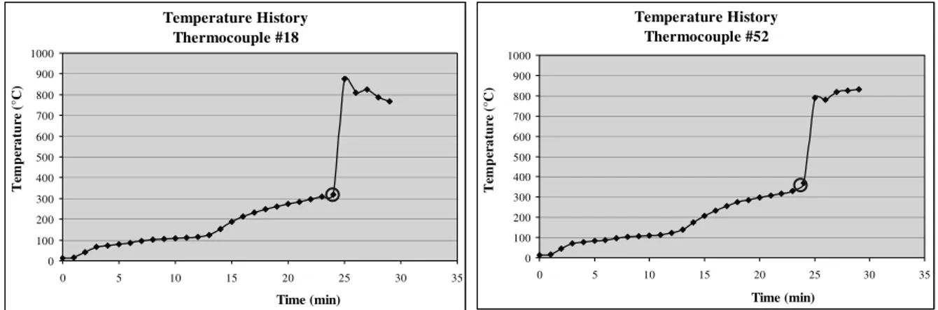
For all thermocouples located on the back face of gypsum board layers (six for each layer), the temperature recorded was plotted against time. An important characteristic identified in these temperature history graphs was a sudden and significant increase in temperature over a period of one or a few minutes only (often an increase of more than 300°C over a period of a minute). As an example for the reader, two temperature history graphs, from two of the thermocouples (# 18 and # 52) placed on floor assembly FF-01A, are provided in Figure 1. The sudden temperature rise observed seem to correspond to the increase in temperature caused by the fall-off of the gypsum board layer at the location of the thermocouple; the fallen board piece allowing heat to penetrate rapidly into the next layer of the assembly.
Some graphs did not display this expected sudden increase in temperature. Factors that could explain this phenomenon include: data recording was stopped before the layer of gypsum board fell off completely; the gypsum board did not fall at the location of the thermocouple; and the thermocouple studied experienced a malfunction. Another possible explanation is that only cracking or partial gypsum board fall-off occurred at the location of the thermocouple, which would cause the temperature to increase over a longer period of time. To ensure that the temperature increase caused by the fall-off of a gypsum piece would not be accounted for in the determination of the temperature causing the piece to fall off, the temperature at which gypsum board falls off for each thermocouple was established as the last temperature recorded before the sudden temperature rise in the layer. In cases where the step in temperature was not as clearly defined, the average of the two recordings bracketing the base of the sudden temperature rise was taken as the fall-off temperature. Circles were drawn around the selected values in Figure 1 as an example. Temperature histories with no such sudden temperature increase or multiple temperature steps of the same magnitude were ignored when fall-off temperatures were calculated. The fall-off temperature of each gypsum board layer was then computed as the average of the fall-off temperatures found for each thermocouple. Certain subjectivity was used at this stage to ignore data points that seemed erroneous, most probably due to a dysfunction of the thermocouple.
Figure 1: Temperature Histories at the Unexposed Face of the Single Gypsum Board Layer for Assembly FF-01A
Temperature History Thermocouple #18 0 100 200 300 400 500 600 700 800 900 1000 0 5 10 15 20 25 30 35 Time (min) Te m p er a tu re (° C ) Temperature History Thermocouple #52 0 100 200 300 400 500 600 700 800 900 1000 0 5 10 15 20 25 30 35 Time (min) T em p era tu re ( °C )
To verify that the results obtained were consistent with observations made during the experiments, the time corresponding to the temperature of fall-off selected was recorded for each thermocouple and those times were then compared to the fall-off times reported by Elewini, et al3 (see Table 1). It was seen that temperature increases often occurred up to a minute before the first piece fall-off was reported. This could be due to cracking in the gypsum board leading to gypsum board fall-off within a short period of time. Temperatures from the thermocouples with fall-off times outside the expanded time range were discarded. More details are available in Reference 11.
An important temperature difference was noted between non-insulated and insulated assemblies. The highest temperature was found for assemblies with insulation at the bottom of the cavity and the lowest for non-insulated assemblies, as observed with previous approaches. In the case of double gypsum board layer assemblies, base layer fall-off temperatures were again significantly lower than face layer fall-off temperatures. As in previous cases, fall-off temperatures were lower with assemblies using wider screw spacing. This difference seemed to be more significant for base layer temperatures.
This method showed the largest difference in temperature from one category to another or between base and face layers. It also generally displayed the smallest standard deviations for temperature criteria. The temperature criteria determined with this method were lower than the preceding ones. This might explain the fact that the criteria found here actually correspond to the temperature at which cracking is initiated and heat starts penetrating the floor cavity to cause gypsum board fall-off, as opposed to the actual temperature at the time of fall-off. This should be considered when applying the results of this study to numerical modelling.
Only this approach accounts for the fact that gypsum board layers fall in separate pieces at unevenly distributed intervals to determine the temperature of fall-off. By considering each thermocouple separately, this method ensures that the temperature selected represents gypsum board fall-off as closely as the temperatures recorded allow it. Indeed, while other methods used a generic time of fall-off to determine the temperature criteria to use, this method is based on the fall-off of a gypsum piece at the location of the thermocouple. The temperature obtained is thus truly the temperature at the time of gypsum board fall-off.
This method is also the only method that distinguishes from temperature that causes gypsum board to fall and temperature increase caused by the fall-off of gypsum board. As discussed earlier, the temperature increase caused by gypsum board fall-off can often be of more than 300°C, so that any method attempting to select a temperature criteria based solely on observed fall-off time will lack the accuracy this method can provide by differentiating the two separate phenomena.
The most important drawback of this method of determining temperature criteria for gypsum board is its subjectivity. Indeed, the location of the sudden temperature rise on the temperature history graphs was not always definite and a fair amount of subjectivity was often necessary to select the appropriate temperature. Also, when determining the fall-off temperature of each assembly, data points that did not follow the trend established by other points were sometimes ignored.
SELECTED CRITERIA
After comparing the results obtained with all approaches described above, temperature criteria were compiled. The sudden rise in temperature criteria was preferred due to the numerous advantages of this method that were identified above. The most important reason for this choice is the fact that fall-off temperatures using
this method are determined in a manner that ensures the temperature increase caused by the fall-off of a gypsum piece is not accounted for in the determination of the temperature causing gypsum board to fall off. Final temperature criteria reported here are based on this last analysis. Table 2 shows the selected failure criteria. The values found in this table are taken at the back face of each gypsum board and are based on assemblies constructed with resilient channels. The installation of resilient channels in double layer floor assemblies did not impact the fall-off temperature of gypsum board face layers, which do not come directly in contact with them. In contrast, the recorded fall-off temperatures for base layers, as well as gypsum boards in single layer assemblies, were significantly reduced (by approximately 100°C) in assemblies built without resilient channels. The temperatures found in Table 2 are intended for use with 12.7 mm thick Type X gypsum boards. On average, the temperatures were found to be higher for thicker gypsum boards, but it was not possible to establish a clear relationship between board thickness and fall-off temperature due to the limited number of assemblies built with 15.9 mm thick Type X gypsum boards. No single gypsum board layer assembly with 610 mm screw spacing was tested. Only one double layer assembly with sprayed-on insulation and screw spacing at 406 mm was tested and experimental results were not sufficiently consistent for a judgment to be made on the fall-off temperature to use.
Table 2: Summary of Temperature Criteria Selected
Face Layer Base Layer
600 *** 600 450 *** 375 425 300 600 500 675 650 *** 650 *** Insulation
Assembly Characteristics Fall-Off Temperature
(ºC)
No Insulation
Double Layer Assembly Single Layer Assembly Screw Spacing (mm) 450 *** 625 Insulation against Gypsum Board Layers Sprayed-on Insulation 406 610 406 610 406 610 DISCUSSION OF RESULTS
Interesting observations were derived from the results of the previous analyses. Firstly, the presence and the location of the insulation within the floor assembly were identified as the major factors influencing the temperature of fall-off of gypsum board layers. It was observed that fall-off temperatures were lowest for non-insulated assemblies, and highest when the insulation was applied directly against the gypsum board layers. This suggests that gypsum fall-off temperature depends on the rate at which heat accumulates in the board. Investigation of the severity of fire exposure using time and temperature relationships could potentially provide a more generic fall-off criteria for numerical modelling. This would require calculating the cumulative board temperature between the beginning of the fire test and the time of fall-off of the assembly.
Screw spacing, i.e. loading per screw on a gypsum board sheet, appears to influence the temperature of fall-off of gypsum board. With all four methods, the temperature of fall-off was noted to be lower for assemblies with wider screw spacing. Screw spacing on a gypsum board sheet dictates the number of screws used, and thus the loading on each screw. The larger loading per screw on assemblies with wider screw spacing causes larger stresses in the
board at the screw locations. This could reduce the capacity of the board to sustain additional stress and cracking could also be induced more quickly at points under high stress in the board. These factors combined would explain why gypsum board falls off at a lower temperature for assemblies using wider screw spacing.
It was also seen that, in the case of double layer gypsum board assemblies, the fall-off temperature of the face layer of gypsum board tends to be higher than the fall-off temperature of single gypsum board layer assemblies, while the base layer fall-off temperatures are usually significantly lower than face layer fall-off temperatures. Face layer temperatures are expected to be higher in double layer gypsum board assemblies than in single layer assemblies, since the second gypsum layer acts as an additional insulation layer. The low temperatures associated with the fall-off of gypsum board base layer, on the other hand, are most likely caused by internal chemical changes occurring in the gypsum boards even while they are protected from large temperature increases by face layers of gypsum.
Thirdly, the installation of resilient channels was noted to have an impact on the fall-off temperature of gypsum board layers directly in contact with the channels, namely single and base layers. This impact is possibly due to an increase in flexibility in the layer supporting the board, which would reduce the deformations to which the board is subjected. It can be supposed that, in increasing the time of fall-off of the gypsum layer, resilient channels also allow more heat to penetrate the boards before fall-off.
SUMMARY OF FINDINGS
In this paper, attempts were made to establish temperature failure criteria for gypsum board using different methods. Key observations made from the results of the analysis presented earlier are summarized here.
The temperature of gypsum board at the first piece fall-off is not an appropriate criterion for gypsum board failure, as it varies too extensively from assembly to assembly, with no identifiable correlation to assembly parameters. The temperature at the time of fall-off of the last piece of each layer does not reflect any actual physical phenomenon. Because the last piece of a gypsum layer often falls during the last few minutes of the test (sometimes even after failure of the assembly tested), the temperature recorded simply approaches the furnace temperature. The average fall-off temperature depends too widely on the first and last piece fall-off temperatures to give any conclusive results. While the average fall-off temperatures were found to be closer for similar assemblies than in the case of first piece fall-off temperatures, the lack of physical meaning of this method was still evident. The temperatures obtained using the average time of fall-off were greatly affected by the increase in temperature in the floor cavity caused by partial gypsum board fall-off, which allowed hot gases to enter the floor cavity. Finally, the last fall-off criteria used, based on the sudden temperature rise observed, provides the most interesting and closely related results. It also presents clear physical meaning due to its microscopic approach and separates the temperature increase caused by gypsum board fall-off from the fall-off criteria.
ACKNOWLEDGEMENTS
The authors wish to acknowledge the technical and financial contributions of the partners in the Floors-I and Floors-II Joint Research Project. The partners include Boise Cascade, Canada Mortgage and Housing Corporation, Canadian Home Builder Association, Canadian Portland Cement Association, Canadian Sheet Steel Building Institute, Canadian Steel Construction Council, Canadian Wood Council, Cellulose Insulation Manufacturers Association of Canada, Forintek Canada Corporation, US Gypsum Association, Gypsum Manufacturers of Canada, Louisiana-Pacific Corporation, Nascor Inc., Ontario Home Warranty Program, Ontario Ministry of Municipal Affairs and Housing, Truss Plate Institute,
Truss Plate Institute of Canada, US Cellulose Manufacturers Association, Johns Manville International, Owens-Corning Canada, Willamette Industries, Roxul Inc., Trus Joist MacMillan.
The authors also wish to thank John Latour, Patrice Leroux,, Roch Monette, Yves Séguin, Richard Rombough and Jocelyn Henrie for constructing assemblies and conducting tests.
REFERENCES
1. Sultan, M.A., Séguin,Y.P., Leroux, “Results of Fire Resistance Tests on Full-Scale Floor Assemblies”, Internal Report No. 764, Institute for Research in Construction, National Research Council of Canada, Ottawa, ON, 1998.
2. Sultan, M.A, Latour, J.C., Leroux, P., Monette, R.C., Seguin, Y.P. and Henrie, J. “Results of Fire Resistance Tests on Full-scale Floor Assemblies – Phase II”, Research Report 184, Institute for Research in Construction, National Research Council Canada, Ottawa, Ontario, 2005.
3. Elewini, et al, E., Mohamed A. Sultan and George V. Hdjisophoclous, “Gypsum Board Fall-off in Floor Assemblies Exposed to Standard Fires”, Proceedings of the Fire and Materials 2007, Interscience Communications, Ltd, West Yard House, Guildford Grove, London, SE10 8JT, England, 2007.
4. CAN/CSA-A82.31-M91, Gypsum Board Application, Canadian Standards Association, Rexdale, ON, 1991.
5. CSA A101-M83, Thermal Insulation, Canadian Standards Association, Rexdale, Ontario, 1983.
6. CAN/ULC-S702-M97, Standard for Mineral Fibre Thermal Insulation for Buildings, Underwriters’ Laboratories of Canada, Scarborough, Ontario, 1997.
7. CAN/CGSB 51.60-M90, Cellulose Fibre Loose Fill Thermal Insulation, Canadian Standards Board, Ottawa, Ontario, 1990.
8. CAN/CSA-82.27-M91, Gypsum Board, Canadian Standards Association, Etobicoke, Ontario, Canada, 1991.
9. ASTM C36-97, Standard Specification for Gypsum Wallboard, American Society for Testing and Materials, West Conshohocken, PA, June 1997.
10. CAN/ULC-S101-M89, Standard Methods of Fire Endurance Tests of Building Construction and Materials. Underwriters' Laboratories of Canada, Scarborough, ON, 1989.
11. Roy-Poirier, A. and Sultan M.A., “Approaches for Determining Gypsum Board Fall-Off Temperature in Floor Assemblies Exposed to Standard Fires”, Research Report 226, Institute for Research in Construction, National Research Council Canada, Ottawa, Ontario, 2007.