Publisher’s version / Version de l'éditeur:
Optical Engineering, 47, 3, pp. 033601-1-033601-9, 2008-03-21
READ THESE TERMS AND CONDITIONS CAREFULLY BEFORE USING THIS WEBSITE. https://nrc-publications.canada.ca/eng/copyright
Vous avez des questions? Nous pouvons vous aider. Pour communiquer directement avec un auteur, consultez la première page de la revue dans laquelle son article a été publié afin de trouver ses coordonnées. Si vous n’arrivez pas à les repérer, communiquez avec nous à [email protected].
Questions? Contact the NRC Publications Archive team at
[email protected]. If you wish to email the authors directly, please see the first page of the publication for their contact information.
NRC Publications Archive
Archives des publications du CNRC
This publication could be one of several versions: author’s original, accepted manuscript or the publisher’s version. / La version de cette publication peut être l’une des suivantes : la version prépublication de l’auteur, la version acceptée du manuscrit ou la version de l’éditeur.
For the publisher’s version, please access the DOI link below./ Pour consulter la version de l’éditeur, utilisez le lien DOI ci-dessous.
https://doi.org/10.1117/1.2896455
Access and use of this website and the material on it are subject to the Terms and Conditions set forth at
Particle size measurement in glass powder beds using optical
coherence tomography
Veilleux, Jocelyn; Moreau, Christian; Lévesque, Daniel; Dufour, Marc;
Boulos, Maher
https://publications-cnrc.canada.ca/fra/droits
L’accès à ce site Web et l’utilisation de son contenu sont assujettis aux conditions présentées dans le site LISEZ CES CONDITIONS ATTENTIVEMENT AVANT D’UTILISER CE SITE WEB.
NRC Publications Record / Notice d'Archives des publications de CNRC:
https://nrc-publications.canada.ca/eng/view/object/?id=9b004da8-331e-4d66-a933-e2835e697829 https://publications-cnrc.canada.ca/fra/voir/objet/?id=9b004da8-331e-4d66-a933-e2835e697829Christian Moreau Daniel Lévesque
Marc Dufour,MEMBER SPIE
National Research Council Canada Industrial Materials Institute 75 de Mortagne Blvd.
Boucherville 共Québec兲, J4B 6Y4, Canada E-mail: [email protected]
Maher Boulos
Université de Sherbrooke
Department of Chemical Engineering 2500 de l’Université Blvd.
Sherbrooke 共Québec兲, J1K 2R1, Canada
beds, is obtained by appropriate peak distance measurements on threshold-selected envelopes after having performed the surface profilo-metry. The measured distributions are in good agreement with those obtained by laser diffraction. When considering the whole powder vol-ume, the evaluation of the mean light penetration depth inside the pow-der beds proves to be a useful approach to evaluate the mean particle diameter, although no information is obtained on the actual particle size distribution in this case. Two simplified models are introduced to under-stand the linear relationship observed between the penetration depth and the mean particle size.© 2008 Society of Photo-Optical Instrumentation
Engineers. 关DOI: 10.1117/1.2896455兴
Subject terms: particle sizing; size distribution; optical coherence tomography; glass powders.
Paper 070544R received Jun. 26, 2007; revised manuscript received Nov. 1, 2007; accepted for publication Nov. 8, 2007; published online Mar. 21, 2008.
1 Introduction
Particle size measurements are nowadays involved in a va-riety of industrial processes, such as the manufacture of polymer fillers, of ceramic or metallic powders, and of pharmaceutical products. As well, they have been intro-duced in biological applications to retrieve the size distri-butions of cell nuclei and mitochondria, which can be re-lated to the detection of preinvasive cancer cells.1 In pollution control applications, they are commonly used to monitor aerosols,2 fumes and exhaust gases,3 and water.4 Consequently, a large number of particle sizing techniques have been investigated over the past years, but none has emerged as a universal technique. In fact, to the diversity of applications corresponds a multiplicity of methods, each having its own advantages and drawbacks.5 To select the appropriate method for a specific application, one has to consider the particle properties to be measured共size, speed, concentration, refractive index, etc.兲, the environmental constraints 共accessibility, temperature, etc.兲, and the mea-surement purpose 共fine distribution measurement or coarse product control兲.6These considerations will eventually dic-tate whether to choose sieving, an electrical low-pressure impactor, centrifugation, micrograph and image analysis, an optical technique 共holography, laser dual Doppler an-emometry, laser diffraction, light scattering spectroscopy, multiwavelength extinction, etc.兲, or any other method available.
However, optical techniques are usually the most suit-able for on-line investigation of particles in industrial
applications,7,8 since they are generally noninvasive and can be adapted to precisely measure a wide range of par-ticle size, speed, and concentration. Moreover, sensitive hardware components can be remotely located from the in-process sample volume of the particles, the signal being effectively carried through optical fibers. The latter charac-teristic constitutes an important advantage of low-coherence interferometry共LCI兲 over traditional diffraction-based optical particle sizers. In fact, diffraction-diffraction-based particle sizers rely on the measurement of the angular dis-tribution of the light scattered at low angles in the forward direction by the sample.9 Therefore, it requires a nearby sensor array共or a moving sensor兲 to detect diffracted light. In a LCI system, both the sample beam and the backscat-tered signal from the sample are collected through the same optics, reducing the invasiveness of the measuring appara-tus. Moreover, LCI can be combined with light scattering spectroscopy to determine particle size and refractive index by measuring variations in scattering distributions with angle10,11 or wavelength.12 Such systems couple a broad-band light source into a Michelson interferometer to pro-vide depth resolution, as in optical coherence tomography 共OCT兲, and include an imaging system that permits the variation of the reference field angle in the detector plane. Probing results were obtained on polystyrene microsphere suspensions11共with mean diameter of 10m or less兲, and the size determination requires a comparison of measured data with the theoretical predictions of Mie theory. Multiple scattering also proves to have significant effects on the ac-curacy of results as the penetration depth is increased.11,13,14 In the present work, we apply LCI in an OCT system to measure the size distribution of dry glass powders with
mean particle diameter ranging from 8 to 175m. One important aspect is that the proposed technique does not use Mie theory to retrieve the scatterer size. Measurements are carried out by inspecting the packed particle beds from the top surface. It is noticed that the lower diameter limit is fixed by the OCT system axial resolution, which depends on the light source coherence length. Microsphere size de-termination is directly performed on cross-sectional images by first considering the microsphere layers located at the surface of the powder beds. The resulting distributions are in good agreement with those obtained by laser diffraction. In another approach, we investigate the relationship be-tween the mean light penetration depth and the mean par-ticle size in the powder beds. We show that, even in the presence of multiple scattering, the light penetration depth is linearly related to the microsphere diameter. Such a rela-tion is consistent with results obtained by modeling light attenuation in two simplified cases:共i兲 added contributions of single spherical particles irradiated by a plane wave共Mie theory兲 and 共ii兲 a stack of glass plates irradiated by a col-limated beam.
2 Method and Apparatus
Glass powders of five different size distributions were ob-tained by sieving glass beads used for shot penning. Par-ticle shape, surface finish, and parPar-ticle size distribution were characterized by scanning electron microscopy 共Hita-chi S-4700兲 and by laser diffraction 共Beckman Coulter LS 13 320兲. Figure 1 illustrates the microsphere surface, whereas the size distributions of the five powders investi-gated in this study are shown in Fig. 6. The glass powders are numbered sequentially from 1 to 5 in order of increas-ing diameter; their cumulative distribution intervals 关10% smaller; 90% smaller兴 are given by 关8;22兴, 关17; 42兴, 关27; 52兴, 关50; 96兴, and 关104; 144兴m, respectively.
The glass powders were poured into small cups to form dense particle beds and were then imaged using a fiber-based 共single-mode SMF-28兲 OCT system, as shown in Fig. 2. The light emitted by a Covega superluminescent diode共SLD兲, with a center wavelength of 1320 nm and a bandwidth ⌬ of 70 nm, is divided at a beamsplitter共BS兲 into two optical paths that are respectively oriented towards the reference mirror and the sample powder. The maximum emitted power is 17 mW, of which only 10% is coupled
into the interferometer, to avoid saturation of the photode-tector 共Thorlabs FGA-04兲. When the light returns, if the optical path length mismatch between the reference and sample arms is shorter than the light coherence length, the sample backscattered field and the reference field will com-bine to produce an interference signal共called an interfero-gram兲, which is collected by the photodetector, amplified, and digitally processed共filtered and demodulated兲. Data ac-quisition is performed by a two-channel, 14-bit analog-to-digital converter running at 4 Msample/s. By recording this interference signal as the reference mirror is synchronously translated, the axial profile of the sample backscattering properties can be obtained.
The axial resolution of the OCT system depends on the coherence length of the light source, and a high resolution can be achieved independently of the sample arm optics. For a Gaussian source, it can be shown15 that the axial resolution ⌬z of the OCT system is inversely proportional to the power spectrum bandwidth, that is, ⌬z = 2 ln2共2/⌬兲 /. The system used in the present
experi-ment has an axial resolution共in air兲 of 11m and a sample probe transverse resolution of about 12m共a 2-mm-wide collimated beam focused by a 14.5-mm-focal-length lens兲. The collecting numerical aperture of the system is NA = 0.07. The focal spot is located approximately at the pow-der surface. For each powpow-der, 16 cross-sectional images共or
B scans兲 were collected, a single B scan being formed by 2000 contiguous interferograms 共or A scans兲. Scanning is performed by moving the probe over the surface using a motorized slide driven by a stepper motor. The step size between two successive interferograms was adjusted to 1 m, while the probing depth step size 共on the optical axis兲 was set to / 8 = 0.165m when collecting the inter-ferogram. However, during the demodulation process, each envelope was resampled at 1 point/m. The optical delay line is made of a rotating rhombic prism mounted on a galvanometer; it has a scanning rate of 148 Hz and a maxi-mal probed depth of 4 mm共details of the optical delay line are given elsewhere16兲. The separation between two con-secutive cross-sectional images was held at 50m.
Fig. 1 SEM micrography of powder 2, showing its spherical
mor-phology and its surface finish. Small surface roughness appears as white asperities.
Fig. 2 Schematic representation of the OCT system. SLD and BS
stand for superluminescent diode and beamsplitter, respectively. Veilleux et al.: Particle size measurement in glass powder beds…
where A stands for the signal amplitude as collected by the OCT system and max关 兴 is the maximum value of the ex-pression inside the brackets共the maximal value being taken over the whole cross-sectional image兲.
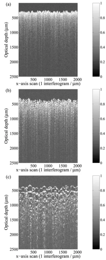
Three particularities can be noted when analyzing the cross-sectional images shown in Fig. 3. Firstly, when the microsphere diameter increases, it becomes easier to distin-guish individual microspheres at the surface of the powder bed, since local air-glass and glass-air interfaces generate a clearly resolved structure. However, for larger penetration depth, no structural peak can be identified in the back-ground of multiply scattered signal and noise. Secondly, the observed light penetration depth seems larger for larger par-ticle diameters. This observation can be explained by the reduction of the number of scattering sites per unit volume when the microsphere diameter increases. Thirdly, almost the whole top hemisphere of particles at the bed surface can be observed in the cross-sectional image of powder 5. This may appear surprising in that a perfectly focused light beam on the apex of a single and smooth microsphere should prevent such a result. The observation is attributed to the surface roughness of the particles, which generates diffuse reflections共the size of asperities may be as large as the wavelength used, as shown in Fig. 1兲. Moreover, the finite depth of field of the optical system may contribute to the observation discussed here. Indeed, preliminary ray-tracing simulations on a perfectly smooth microsphere sug-gest that the relative light intensity coupled into the fiber decays in a slower manner as the probe moves away from the microsphere apex, provided the apex is off focus.
The last observation is not discussed further here, whereas the former two observations 共individual micro-spheres distinguishable near the surface and an apparent increase in penetration depth with particle size兲 are used to identify two corresponding approaches to retrieve the mi-crosphere diameter: a processing method for the first par-ticle layers共from which the particle size distribution is ob-tained兲 and another method based on the calculation of the light penetration depth 共from which the mean particle size is obtained兲.
3.2 Near-Surface Particle Size Distribution
The first investigated approach is based on the hypothesis that maximum signal peaks will be obtained when the sample beam impinges on the apex of a single microsphere surface and exits at the bottom surface 共justified by the small NA⫽0.07兲. Both air-glass and glass-air interfaces crossed along this optical path result in an abrupt refractive index variation that reflects a signal towards the
interferom-eter. Therefore, measuring the distance between the corre-sponding peaks on the interferogram envelope provides an evaluation of the microsphere geometric diameter Dsph
us-ing the expression
Fig. 3 Examples of OCT cross-sectional images acquired for 共a兲
powder 1, 共b兲 powder 3, and 共c兲 powder 5. The normalized logarith-mic amplitude is represented on a 256-level grayscale.
Dsph=d/nglass, 共2兲
where d is the distance between peaks, is a correction factor, and nglassis the refractive index of the microsphere.
The determination of the correction factor , which in-volves the relationship between a spherical particle and a circular trace intersected by a random plane of finite thick-ness共focal spot width兲, is not straightforward. Such circular traces are shown for a random close packing of spheres in Fig. 4. Attempts to apply Schwartz-Saltykov method17 to evaluate the correction factor led to intrinsic difficulties re-lated to the underrepresentation of circular traces having smaller diameters. In fact, light reflections generated away from the apex area of small microspheres共corresponding to powders 1 to 4兲, which should generate most of the ex-pected smaller circular traces, are hardly collected with OCT. The small numerical aperture and the large focal spot width are the major obstacles. Consequently, calculation of a correction factor based on the Schwartz-Saltykov method does not appear practical at this point, and another method was chosen.
An algorithmic approach was developed to circumvent the correction factor calculation. This is done by selecting interferogram envelopes in cross-sectional images from the local apexes of microspheres. Formally, this envelope se-lection, applied in a left-to-right manner in cross-sectional images, does not remove the need for a back-to-front plane intersection correction 共Fig. 4兲. However, by applying a proper amplitude threshold algorithm as described below, the additional correction should be made very small, since the reflected light intensity is maximal in two cases: when the center of the focused beam Raleigh range coincides with the apex of a microsphere, and when the beam wave front curvature matches the microsphere curvature. How-ever, on taking into account the sample probe optics used in this experiment, the latter case is seen to be improbable, since it would require microspheres having a diameter larger than 350m. Thus, one can safely consider that the
reflected light intensity is maximal when the focused beam Raleigh range coincides with the apex of a microsphere only.
In detail, the approach developed consists in a two-step algorithm applied to each cross-sectional image. The first step performs the profilometry of the powder bed surface and identifies the interferogram envelopes associated with the local apexes on the microspheres, as shown in Fig. 5共a兲. With this approach, only one interferogram envelope is se-lected on each microsphere, avoiding the overrepresenta-tion of larger particles. Then, the second step applies to selected envelopes an amplitude threshold fixed at a certain percentage of the mean amplitude of the most intense peaks in the considered cross-sectional image. In this work, a threshold fixed at 20% of the mean amplitude of the 10 largest peaks was selected. Based on the hypothesis of maximum signal peaks, this second step removes undesired low-amplitude signals and permits the measurement of d, the distance between peaks, as depicted in Fig. 5共b兲. Thus, using this algorithm to select appropriate interferogram en-velopes almost eliminates the need for a correction factor, and Eq. 共2兲 can be reduced to Dsph= d / nglass. From a
mea-Fig. 4 Schematic representation of a cross section 共shown on front
plane兲 taken on a random close pack of spheres having a uniform diameter.
Fig. 5 共a兲 Profilometry of the powder surface 共solid black line兲 and
identification of interferogram envelopes corresponding to micro-sphere apexes 共black dots兲. 共b兲 Linear amplitude of interferogram envelope located at x = 384m, showing the relationship between peak positions and microsphere surfaces crossed by the sample beam.
sured nglass= 1.5⫾ 0.1, obtained with OCT on a single large
microsphere by comparing the geometrical and optical di-ameters 共denoted Dsphgeom and D
sph
opt, respectively, with n glass
= Dsphopt/D
sph
geom兲, the microsphere diameter for all selected
envelopes on all cross-sectional images collected can be calculated.
The microsphere diameter data are then used to plot the size distributions of the five powders studied, as shown in Fig. 6. The analysis just described is valid as long as the two analyzed reflections come from the top and bottom surfaces of the same microsphere. If this is not the case, abnormally small or large diameter values can be obtained. For example, an abnormally small diameter value could be due to the presence of noise on a signal generated at a single air-glass interface. Indeed, the algorithm could falsely identify two distinct peaks close to each other, lead-ing to an artificially small diameter value. On the opposite side, if the amplitude of the peak associated with the sec-ond interface of a microsphere is smaller than the applied threshold, and if a subsequent peak exceeds this threshold, then the diameter measurement will be biased upwards. In the results presented in Fig. 6, measurements corresponding to 2.5% smaller and larger diameters of the distributions are removed to avoid biasing the results due to those false de-tections. The resulting OCT size distributions can be fitted with a normal distribution, normalized, and compared with the distributions obtained by laser diffraction, as shown in Fig. 6. The measured distributions are in good agreement with those obtained by laser diffraction. A comparison of the mean values and standard deviations of the two series of measurements is shown in Table 1.
One might expect a shift towards larger diameters of the OCT distribution of powder 1 关Fig. 6共a兲兴, since the optical
axial resolution is limited to 11m. However, less than 10% of the microspheres have a geometrical diameter smaller than 11/ 1.5= 7.3m, and that explains why the expected shift is not observed. Also, notice in Fig. 6共c兲 the significant left shoulder on the distribution of powder 3 obtained by laser diffraction. Diameters obtained with OCT indeed present this shoulder, but the Gaussian fit in this case results in a slight left shift of the mean and in a larger standard deviation. Overall, the agreement between the two techniques is excellent, and it validates the application of the proposed approach to determining the size distribution of particles located near the surface of the powder beds. One should not expect any difficulty in retrieving the diam-eter of even larger microspheres共diameter ⬎175m兲 with this technique.
Fig. 6 Comparison of microsphere size distributions as obtained by optical coherence tomography
共OCT兲 and laser diffraction 共LD兲: 共a兲 to 共e兲 for powders 1 to 5, respectively.
Table 1 Mean values 共兲 and standard deviations 共兲 of the five studied powders as obtained by laser diffraction and OCT.
Powder Laser diffraction OCT
共m兲 共m兲 共m兲 共m兲 1 15 6 17 5 2 30 9 33 8 3 41 10 45 12 4 73 19 67 18 5 123 17 121 14
3.3 Mean Particle Size and Light Penetration Depth
3.3.1 Light penetration depth measurement
The second approach to retrieve diameter-related informa-tion from OCT cross-secinforma-tional images relies on the appar-ent relationship between the light penetration depth and the particle diameter, as observed in Fig. 3. An exact descrip-tion of the propagadescrip-tion of a focused beam inside a highly scattering medium represents a very complex problem.13,14,18,19 Because such an exact description goes beyond the objectives of the present study, the following development rather aims at establishing a correlation be-tween an OCT signal characteristic共effective light penetra-tion depth兲 and the mean particle size.
The mean or effective penetration depth␦effis defined as
␦eff=
兺
i=0 N ziAi兺
i=0 N Ai , 共3兲where ziis the optical depth of the i’th point on an
inter-ferogram envelope 共with zi= ⌬i, ⌬ being the acquisition
step size兲, Aiis the signal amplitude collected at this depth,
and N is the number of points per interferogram envelope. Equation 共3兲 is used to calculate the penetration ␦eff for
each interferogram envelope j = 1 , 2 , . . . , 2000 forming the cross-sectional image共not only those corresponding to mi-crosphere apexes兲, and an average value is calculated.
Theoretically, it can be easily shown that, for an expo-nentially decaying signal amplitude A = A0exp共−z /␦兲 de-scribing a single-scattering problem, ␦eff corresponds
ex-actly to the physical light penetration depth␦for a window of sufficiently large optical depth. The mean-penetration-depth calculation proves to be more robust and less prone to interferogram amplitude variations than the usual slope measurement on the logarithmic amplitude plot of lnA = lnA0− z /␦. In particular, the slope measurement is
influ-enced by the significant signal amplitude associated with the first microsphere surface 共almost a specular reflection兲 and by the identification of the optical depth where multiple scattering begins. Thus, a shallower or steeper slope than envisaged might result. It is worth mentioning that the cal-culation of␦effas defined in Eq.共3兲 stays useful when the
effects of multiple scattering appear, even though its pre-cise physical interpretation is more difficult to establish in this case. Indeed, the penetration depth obtained with the calculation of␦effreflects with more accuracy what is truly
observed on a B scan 共see Fig. 3兲 than what would be calculated from the slope of the logarithmic amplitude plot of lnA = lnA0− z /␦. Still, a Monte Carlo simulation such as
the one conducted by Karamata et al.19may help provide a physical interpretation for␦eff.
3.3.2 Results and discussion
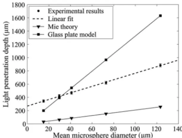
Figure 7 illustrates the observed relationship between the penetration depth␦effof cross-sectional images and the
cor-responding mean microsphere diameter of the powders. The error bars correspond to the standard deviation of the calculated penetration for the 16 cross-sectional images. As shown in Fig. 7, a linear relationship is found between␦eff
and the microsphere diameter. It is interesting to compare the mean penetration depths observed in this study with
theoretical predictions of models that can approximate, as limiting cases, the light scattering in the powder beds. Clearly, these predictions are not exact, but they bring out interesting comparison points to stimulate further research in this field. Figure 7 shows the comparison of observed penetration depths with those based on 共i兲 Mie scattering theory for spheres and 共ii兲 normal incidence of a parallel beam on a stack of glass plates. The illumination conditions in theses cases are schematically represented in Fig. 8 and compared with the real situation.
The penetration depth ␦eff is much larger than the one
theoretically predicted from the Mie theory 共see Sec. 5兲. Strictly speaking, Mie theory does not apply for randomly close-packed powders. Indeed, the large volume fraction of particles, the finite dimension of the light beam, and mul-tiple scattering all limit the validity of a scattering model based on Mie theory. In fact, according to Yadlowsky et al.,13multiple scattering significantly reduces the light am-plitude decrease below the single-scattering prediction, as observed in the present study. Moreover, the plane wave
Fig. 7 Comparison of measured mean penetration depth ␦effwith
results predicted from the Mie theory and the glass plate model for different microsphere diameters.
Fig. 8 Schematic representation of illumination conditions. Mie
scattering applies for an incident plane wave over a single small sphere. Real conditions have a focused beam with a size compa-rable to the size of microspheres illuminated. Stacked glass plates correspond to large microspheres irradiated by a small collimated 共parallel兲 beam.
with the experimental results. According to this model, the measured light penetration should reach between 13 and 16 times the microsphere diameter. Figure 7 shows the case where the light penetration depth is taken at 13 diameters. The experimental penetrations in Fig. 7 differ from the glass plate results by a factor up to 2. The differences might be explained as follows: The light penetration depth from the glass plate model is very dependent on the chosen equivalent transmission coefficient 共defined in Sec. 6兲. When dealing with microspheres, the sample beam inci-dence angle over air-glass interfaces may differ from nor-mal incidence, some of the light rays being reflected in directions where they are not collected. Therefore, the transmission coefficient used in the model is probably overestimated.
As expected, neither the Mie scattering theory nor the glass plate stacking model successfully reproduces light penetration in a glass powder bed. However, they both show a linear dependence of light penetration on particle diameter, as do the experimental results. Further modeling is needed to understand how the mean penetration depth
␦effis physically related to light penetration when multiple
scattering occurs. For example, one can alternatively use geometrical optics and/or a Monte Carlo approach共as sug-gested earlier兲 to model the incident light beam energy losses as a result of random focusing and defocusing by microspheres. With such modeling, it will be possible to more confidently use the mean penetration depth ␦eff to
determine the microsphere diameter from OCT cross-sectional images.
4 Conclusion
The results presented in this study show that OCT can be used to characterize the particle size of compact micro-sphere beds. The studied micromicro-sphere diameters ranged from 8 to 175m. Two different approaches were devel-oped to determine, respectively, the actual size distribution and the mean diameter of transparent microspheres at the surface of beds.
The diameter distributions obtained from near-surface interpeak distances on amplitude threshold-selected inter-ferogram envelopes were found to be in good agreement with the actual particle size distributions obtained by laser diffraction. Interestingly, the proposed approach does not refer to the Mie scattering theory to retrieve the particle size distribution. However, the technique shows the limita-tion imposed by the axial resolulimita-tion when studying a pow-der that contains microspheres with an optical diameter smaller than the coherence length of the light source used. Another limitation would be the need for a priori
knowl-discrimination of variations in scatterer size and refractive index with depth, as would be observed in a real biological sample.
5 Appendix: Mie Theory Calculation
The Mie-theory-based model starts by considering single scattering. The signal intensity I at an optical depth z can then be expressed as
I= I0exp共−extz兲, 共4兲
where I0 is the initial intensity共at z = 0兲 and ext= ⌸+a
is the extinction coefficient, with a the absorption coeffi-cient, ⌸ the microsphere number density, andthe scatter-ing cross section of a sscatter-ingle microsphere. We mention here that the signal intensity is chosen in Eq.共4兲 to be consistent with Mie theory, but that OCT is sensitive to the backscat-tered field amplitude. At a wavelength of 1.32m, absorp-tion in glass can be neglected and the extincabsorp-tion coefficient reduces to the scattering coefficient 共ext=s= ⌸兲.
How-ever, the scattered light is not completely removed from the incident beam, and a significant portion of optical energy continues to propagate as a forward-scattered component. Therefore, an anisotropy factor g is introduced to give the so-called reduced scattering coefficient s
⬘
=共1 − g兲s,20
which is a better representation of the extinction coefficient under the present imaging condition.
From Eq.共4兲, we can define the light penetration depth␦
as the optical path z for which the intensity ratio is I / I0
= 1 / e2. It is equivalent to a detected OCT amplitude ratio of
1/e. Therefore, when using the reduced scattering coeffi-cient and the approximation of weak absorption, the light penetration depth is expressed as
␦Mie= 2 1 − g· 2 ⌸= 2 1 − g
冋
f冉
v冊
册
−1 , 共5兲where f is the volume fraction of particles and / v is the volume scattering coefficient共scattering cross sectionper unit particle volume v兲. Both g andcan be calculated as functions of microsphere diameter with the Mie scattering theory.21 Figure 7 illustrates the light penetration depth for
f= 0.64共random close-packed powders兲, as calculated with Eq. 共5兲.
The applicability of this model is limited by the require-ment of small scattering contributions to the total attenua-tion共i.e., ⌸h ≪1, with h being the considered slab thick-ness兲. The particle concentration has to be small, which is obviously not the case of random close-packed powders, and multiple scattering cannot be neglected. Moreover, the
incident wave 共focused beam兲 does not verify the plane wave assumption, especially for larger microspheres.
6 Appendix: Stack Model
To facilitate modeling of stacked glass plates, the two in-terfaces共1, glass-air, and 2, air-glass, with transmission and reflection coefficients in amplitude for normal incidence given by t1= 1.2, r1= 0.2, t2= 0.8 and r2= −0.2兲 at the junc-tion between two plates are replaced by a single equivalent interface. The latter transmits t1t2= 0.96 of the amplitude and reflects a proportion r1+ t1t2r2= 0.008. To calculate the
amplitude at a depth of N plates, it is necessary to consider the simple reflection generated at the corresponding inter-face, but also all the combinations of multiple reflections that give the same optical path. Therefore, with teq= 0.96
and req= 0.008 respectively standing for the transmitted and
reflected amplitudes at an equivalent interface, the follow-ing expressions give the asymptotic values of light ampli-tude A at a depth of N plates:
minimum amplitude limit: A共N兲 ⬎ t1t2⫻ teq2共N−1兲req, 共6兲
maximum amplitude limit:
A共N兲 ⬍ t1t2⫻
兺
i=1
N
T共N,i兲teq2共N−i兲reqi r2i−1, 共7兲
where the factor t1t2 represents light transmission through
the top surface of the first glass plate共in and out兲. In Eq. 共7兲, T共N , i兲 corresponds to the triangle of Narayana numbers.22According to this model, the light penetration 共defined at the location where A / A0= 1 / e兲 reaches a depth
between 13 and 16 plates.
Acknowledgments
The financial support by the Natural Sciences and Engi-neering Research Council of Canada 共NSERC兲, the Na-tional Research Council 共NRC兲 of Canada, and the Fonds Québécois de la Recherche sur la Nature et les Technolo-gies共FQRNT兲 is gratefully acknowledged. Helpful discus-sions with Guy Lamouche, as well as the technical support provided by Bruno Gauthier, are greatly appreciated.
References
1. V. Backman, M. B. Wallace, L. T. Perelman, J. T. Arendt, R. Gurjar, M. G. Müller, Q. Zhang, G. Zonios, E. Kline, T. McGillican, S. Shapshay, T. Valdez, K. Badizadegan, J. M. Crawford, M. Fitzmaurice, S. Kabani, H. S. Levin, M. Seiler, R. R. Dasari, I. Itzkan, J. Van Dam, and M. S. Feld, “Detection of preinvasive cancer cells,” Nature (London) 406共6791兲, 35–36 共2000兲.
2. P. Demokritou, S. J. Lee, S. T. Ferguson, and P. Koutrakis, “A com-pactmultistage共cascade兲 impactor for the characterization of atmo-spheric aerosols,” J. Aerosol Sci. 35共3兲, 281–299 共2004兲.
3. M. M. Maricq and N. Xu, “The effective density and fractal dimen-sion of soot particles from premixed flames and motor vehicle ex-haust,” J. Aerosol Sci. 35共10兲, 1251–1274 共2004兲.
4. D. J. Law, A. J. Bale, and S. E. Jones, “Adaptation of focused beam reflectance measurement to in-situ particle sizing in estuaries and coastal waters,” Mar. Geol. 140共1–2兲, 47–59 共1997兲.
5. F. M. Etzler and M. S. Sanderson, “Particle size analysis: a compara-tive study of various methods,” Part. Part. Syst. Charact. 12共5兲, 217– 224共1995兲.
6. A. Kleitz and D. Boulaud, “Granulométrie des particules en mouve-ment et des aerosols,” in Techniques de l’Ingénieur, Dossier R2360, Paris共1995兲.
7. D. L. Black, M. Q. McQuay, and M. P. Bonin, “Laser-based tech-niques for particle-size measurement: a review of sizing methods and
their industrial applications,” Prog. Energy Combust. Sci. 22共3兲, 267– 306共1996兲.
8. I. Gianinoni, E. Golinelli, G. Melzi, S. Musazzi, U. Perini, and F. Trespidi, “Optical particle sizers for on-line applications in industrial plants,” Opt. Lasers Eng. 39共2兲, 141–154 共2003兲.
9. J. Swithenbank, J. M. Beer, D. S. Taylor, D. Abbot, and G. C. McCreath, “A laser diagnostic technique for the measurement of droplet and particle size distribution,” in Am. Inst. Aeronaut.
Astro-naut. 14th Aerospace Sciences Mtg., AIAA-1976-69共1976兲. 10. A. Wax, C. Yang, R. R. Dasari, and M. S. Feld, “Measurement of
angular distributions by use of low-coherence interferometry for light-scattering spectroscopy,” Opt. Lett. 26共6兲, 322–324 共2001兲. 11. A. Wax, C. Yang, V. Backman, M. Kalashnikov, R. R. Dasari, and M.
S. Feld, “Determination of particle size by using the angular distri-bution of backscattered light as measured with low-coherence inter-ferometry,” J. Opt. Soc. Am. A 19共4兲, 737–744 共2002兲.
12. C. Xu, P. S. Carney, and S. A. Boppart, “Wavelength-dependent scat-tering in spectroscopic optical coherence tomography,” Opt. Express
13共14兲, 5450–5462 共2005兲.
13. M. J. Yadlowsky, J. M. Schmitt, and R. F. Booner, “Multiple scatter-ing in optical coherence microscopy,” Appl. Opt. 34共25兲, 5699–5707 共1995兲.
14. J. M. Schmitt and A. Knüttel, “Model of optical coherence tomogra-phy of heterogeneous tissue,” J. Opt. Soc. Am. A 14共6兲, 1231–1242 共1997兲.
15. M. R. Hee, “Optical coherence tomography: theory,” Chap. 2 in
Handbook of Optical Coherence Tomography, B. E. Bouma and G. J. Tearney, Eds., pp. 41–66, Marcel Dekker, New York共2002兲. 16. G. Lamouche, M. Dufour, B. Gauthier, V. Bartulovic, M. Hewko, and
J. P. Monchalin, “Optical delay line using rotating rhombic prisms,” in Coherence Domain Optical Methods and Optical Coherence
To-mography in Biomedicine XI, J. G. Fujimoto, J. A. Izatt, and V. V. Tuchin, Eds., p. 64292G-6, SPIE, San Jose, CA共2007兲.
17. E. E. Underwood, “Particle-size distribution,” in Quantitative
Mi-croscopy, R. T. DeHoff and F. N. Rhines, Eds., pp. 149–200, McGraw-Hill, New York共1968兲.
18. L. Thrane, H. T. Yura, and P. E. Andersen, “Analysis of optical co-herence tomography systems based on the extended Huygens–Fresnel principle,” J. Opt. Soc. Am. A 17共3兲, 484–490 共2000兲.
19. B. Karamata, M. Laubscher, M. Leutenegger, S. Bourquin, and T. Lasser, “Multiple scattering in optical coherence tomography. I. In-vestigation and modelling,” J. Opt. Soc. Am. A 22共7兲, 1369–1379 共2005兲.
20. R. Graaff, J. G. Aarnoudse, J. R. Zijp, P. M. A. Sloot, F. F. M. de Mul, J. Greve, and M. H. Koelink, “Reduced light-scattering properties for mixtures of spherical particles: a simple approximation derived from Mie calculations,” Appl. Opt. 31共10兲, 1370–1376 共1992兲.
21. C. F. Bohren and D. R. Huffman, Absorption and Scattering of Light
by Small Particles, John Wiley & Sons, New York共1983兲. 22. T. V. Narayana, Lattice Path Combinatorics with Statistical
Applica-tions, University of Toronto Press, Toronto共1979兲.
Jocelyn Veilleux received his BEng degree
in engineering physics in 2004 from École Polytechnique de Montréal 共Canada兲, and his MScA degree in chemical engineering in 2006 from Université de Sherbrooke 共Canada兲, where he conducted a research project in partnership with the Industrial Ma-terials Institute of the National Research Council of Canada. Since September 2006, he has been a PhD candidate in chemical engineering at McGill University, Canada. His research interests include optical techniques for the visualization and characterization of nanofluids, materials, and plasmas, as well as fundamentals of heat and mass transfer in two-phase systems.
Christian Moreau received his master’s
degree in nuclear physics in 1981 and his PhD in applied physics in 1985 from Univer-sité Laval, Québec City, Canada. Currently, he is group leader for surface technologies at the Industrial Materials Institute of the National Research Council of Canada. His main research interests are development and use of optical sensors for thermal spray particles. He is editor-in-chief of the Journal
of Thermal Spray Technology.
Marc L. Dufour received his BScA degree
in 1977 and his MEng degree in 1980 from École Polytechnique de Montréal, Canada. He has worked as a research associate with the National Research Council of Canada since 1980 and has developed several opti-cal sensors for industrial on-line applica-tions: arc welding, steel casting, and wood processing. Since 1999, he has been in-volved in the development of low-coherence interference 共LCI兲 sensors for industrial in-spection and catheterized optical coherence tomography 共OCT兲 for biomedical applications.
was inducted into the ASM TSS Hall of Fame in May 2003. Profes-sor Boulos was the recipient of the J.-Armand Bombardier prize of the ACFAS in September 2003, and the ADRIQ Innovator prize in Nov 2003. He was also the recipient of the Jules Stachiewicz Medal in 1996, offered jointly by the Canadian Society of Chemical Engi-neering, and the Canadian Society of Mechanical EngiEngi-neering, for his contributions in the field of heat transfer under plasma conditions.