Publisher’s version / Version de l'éditeur:
Technical Note (National Research Council of Canada. Division of Building Research), 1968-11-01
READ THESE TERMS AND CONDITIONS CAREFULLY BEFORE USING THIS WEBSITE.
https://nrc-publications.canada.ca/eng/copyright
Vous avez des questions? Nous pouvons vous aider. Pour communiquer directement avec un auteur, consultez la première page de la revue dans laquelle son article a été publié afin de trouver ses coordonnées. Si vous n’arrivez pas à les repérer, communiquez avec nous à [email protected].
Questions? Contact the NRC Publications Archive team at
[email protected]. If you wish to email the authors directly, please see the first page of the publication for their contact information.
NRC Publications Archive
Archives des publications du CNRC
For the publisher’s version, please access the DOI link below./ Pour consulter la version de l’éditeur, utilisez le lien DOI ci-dessous.
https://doi.org/10.4224/20358636
Access and use of this website and the material on it are subject to the Terms and Conditions set forth at
Sound Insulations of Some Window Construction
Olynyk, D.
https://publications-cnrc.canada.ca/fra/droits
L’accès à ce site Web et l’utilisation de son contenu sont assujettis aux conditions présentées dans le site LISEZ CES CONDITIONS ATTENTIVEMENT AVANT D’UTILISER CE SITE WEB.
NRC Publications Record / Notice d'Archives des publications de CNRC: https://nrc-publications.canada.ca/eng/view/object/?id=2539e853-e357-425e-acf1-ca4534da3c9e https://publications-cnrc.canada.ca/fra/voir/objet/?id=2539e853-e357-425e-acf1-ca4534da3c9e
NATIONAL RESEARCH COUNCIL OF CANADA
DIVISION OF BUILDING RESEARCH
'l'E
CJHI
N II
C
AIL
NOTJE
No.
526
PREPARED BY D. Olynyk CHECKED BY TDN
APPROVEP By N. B.H.
PREPARED FOR
SUBJECT
Inquiry and Record Purposes
SOUND INSULATIONS OF SOME WINDOW CONSTRUCTION
November 1968.
This note serves as a guide when assessing the sound insulation of glass window constructions. References are provided to transmission loss measurem.ents that have been carried out on many types of single and double glazing.
CRITERIA
The resistance of a building element to the transm.ission of sound between dwellings was first described in terms of an average transmission loss for a series of typical audio test frequencies (100 to 3200 Hz or 125 to 4000 Hz). In the present state of the art, a single-figure rating known as the Sound Transmission Class (STC) (l) has been developed by ASTM. It is believed to be a better criterion as it was derived from some statistics on household dwelling noises and background noise levels.
According to Residential Standards, 1965, Supplement No. 5 to the National Building Code of Canada, a construction with a Sound Transmis-sion Class of 50 or more is considered to provide very good performance in resisting airborne sound between dwellings. With a rating of 45 to 50 there is fair performance in resisting airborne sound. A rating of less than 45 is not acceptable for dwelling separation, although for office sepa-ration, or for walls within a dwelling, lower values can be quite satisfactory.
2
-One must note, however, that the Sound Transmission Class was derived for noises transmitted between dwellings and offices, e. g. , human speech, music and household noises. As the most com.m.on use of windows is to separate the exterior environment from the interior, it is often required that isolation be provided against noise from vehicular traffic; airplanes. etc. The spectra of these noise sources can be quite different from that of typical dwelling noises and one should regard the Sound Transmission Class only as a rough guide when selecting window constructions. A more precise, but more complicated, procedure would be to consider the amplitude and frequency content of the offensive noise, together with the transmission loss characteristics of the wall and/or
window construction in order to determine the nature of the intruding noise.
COMPOSiTE CONSTRUCTIONS
A window or door tha t forms part of a given wall must be
considered when determining the effective insulation of the wall, because the over -all transmission loss of a wall depends on the relative areas and transmission losses of its components. Reverting to first principles (1) consider instead of transmission loss (T L), the sound transmission
coefficient (1"). The sound transmission coefficient is defined as the fraction of incident sound power transmitted through the partition. The two are
related in the following manner:
TL(decibels) = 10logl/'r.
The amount of sound power passing through a building element is propor-tional to the product of the area and sound transmission coefficient, and the following can be shown for a two-component wall system:
where
S is the area of the total wall; r is the effective sound transmission
coefficient for the whole wall; S • Sb are the areas of the com.ponents. and 'f a' 'f b are the sound
エイ。ョウュゥウウゥセョ
coefficients of the components.r S
+
'fbSb a a Then r = S S "bSb)-and TL = 10 log(" S
+
a a3
-A graph to facilitate this calculation, together with a working example. is shown in Figure 1; for the sake of convenience it is given in terms of the transmission loss of each component. It is seen that a significant area of a weak component reduces the benefit of a strong
component in the case where the two components form. a wall. In extreme cases the over -all insulation of a wall cart be limited the transmission loss of the weak component.
Ignoring diffraction, Figure 1 may also be used to estimate the effect of gaps. cracks and openings on the transmission loss of doors. windows, etc. In this case, if the total area of the opening is known, the opening can be considered as the weak component with a transmission loss of 0 decibels. It is seen that it does not take much of an opening to reduce the transmission loss by a significant amount, especially at the higher transmission losses of the given component. To show this effect quantitatively, calculations of the effect of relative area of opening on the transmission loss of a 1/4 in. glazing (No.9 in Table I) are shown graphically in Figure 2. For doors. windows. etc. to be fully effective, care must be taken so that the areas of any cracks, gaps or vent holes do not exceed certain limits.
FACTORS AFFECTING TL OF WINDOW CONSTRUCTIONS
Disregarding flanking transmission, the sound transmission loss of some materials can be estimated by using the m.ass law. This law, applicable to constructions that are homogeneous and limp, states that the transmission loss is approximately proportional to the product of surface weight and test frequency. This law can be demonstrated to some extent for single glazing constructions selected from Table I; in Figure 3 STC is plotted against surface weight. For other constructions the mass law does not apply as there are the phenomena of coincidence and air cavity resonance to contend with.
Panels, such as glass, with high flexural stiffness, have a reduced transmission loss at frequencies above a certain value known as the "coincidence frequency". This is the frequency at which the wavelength of flexural waves in the panel coincides with the wave length of sound in air. The coincidence frequency depends on the thickness and flexural stiffness of the panel, and the depth of the dip in the transmission loss curve depends on the internal damping of the material. For thin glass the coincidence frequency is above the region of importance, but for thickness greater than 1/4 inch it will affect the observed performance. Ordinary glass has low
damping, and consequently a deep, sharply-defined coincidence dip. This problem has been solved by the use of special laminated glass containing a layer of plastic damping material.
4
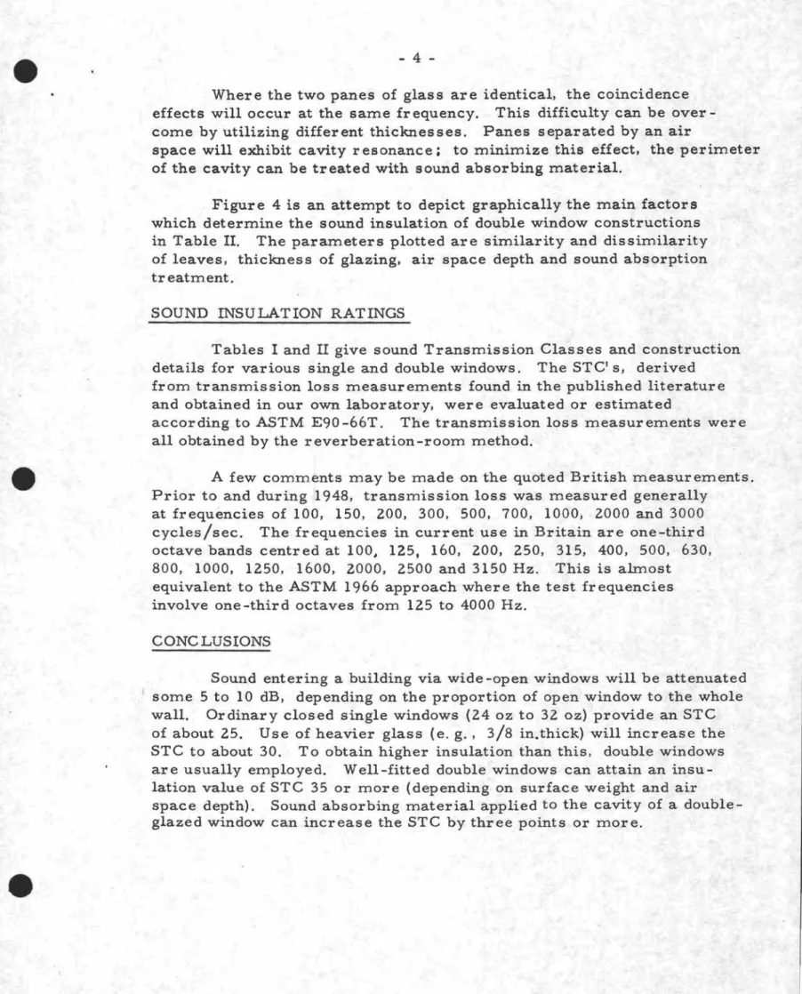
-Where the two panes of glass are identical, the coincidence effects will occur at the same fr equency. This difficulty can be over-come by utilizing different thicknesses. Panes separated by an air
space will exhibit cavity resonance: to minimize this effect, the perimeter of the cavity can be treated with sound absorbing material.
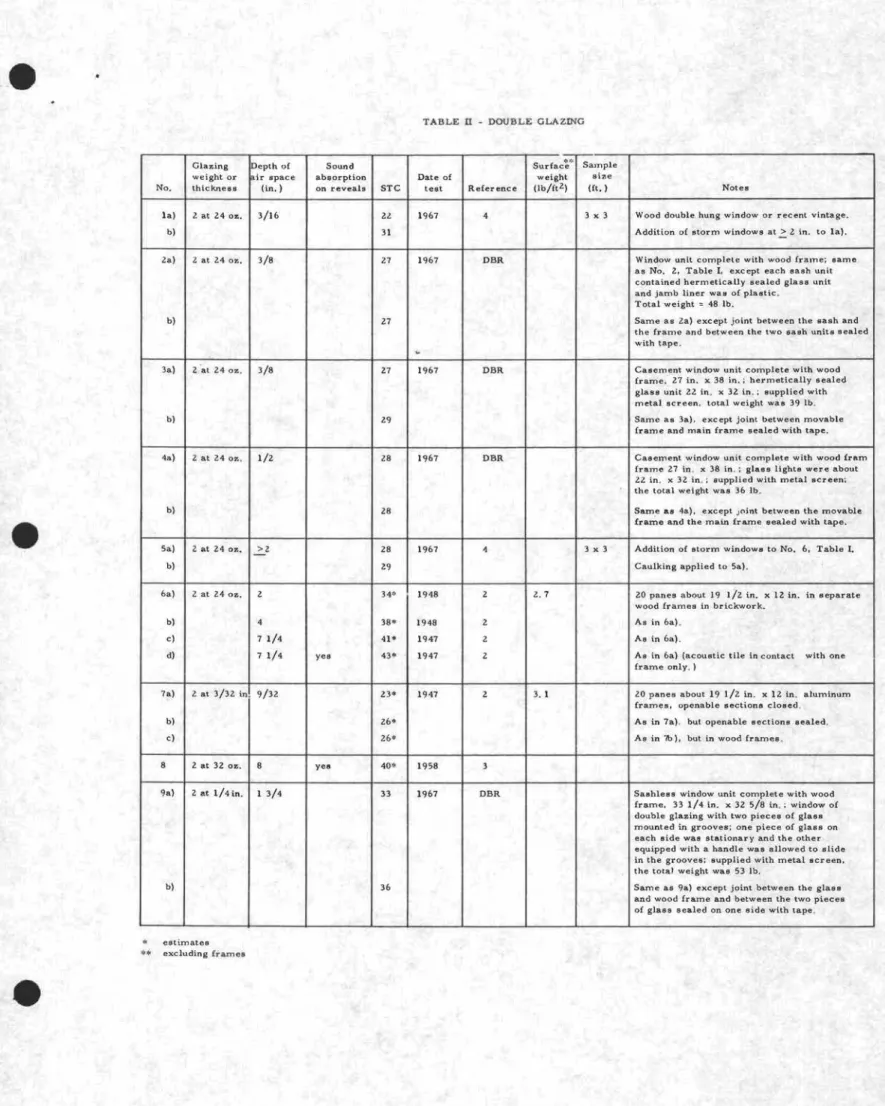
Figure 4 is an attempt to depict graphically the main factors which determine the sound insulation of double window constructions in Table II. The param,eters plotted are similarity and dissimilarity of leaves, thickness of glazing, air space depth and sound absorption treatment.
SOUND INSULATION RATINGS
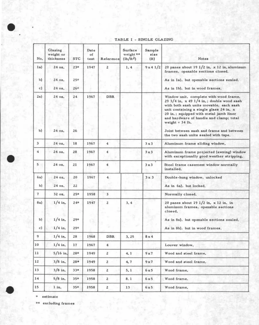
Tables I and II give sound Transmission Classes and construction details for various single and double windows. The STC' s, derived
from transmission loss measurements found in the published literature and obtained in our own laboratory, were evaluated or estimated
according to ASTM E90 -66T. The transmission loss measurements were all obtained by the reverberation-room method.
A few comments may be made on the quoted British measurements. Prior to and during 1948, transmission loss was measured generally
at frequencies of 100, 150, 200, 300, 500, 700, 1000; 2000 and 3000 cycles/sec. The frequencies in current use in Britain are one-third octave bands centred at lOa, 125, 160, 200, 250, 315, 400, 500, 630, 800, 1000, 1250, 1600, 2000, 2500 and 3150 Hz. This is almost equivalent to the ASTM 1966 approach where the test frequencies involve one-third octaves from 125 to 4000 Hz.
CONC LUSIONS
Sound entering a building via wide -open windows will be attenuated some 5 to 10 dB, depending on the proportion of open window to the whole wall. Ordinary closed single windows (24 oz to 32 oz) provide an STC of about 25. Use of heavier glass (e. g., 3/8 in. thick) will increase the STC to about 30. To obtain higher insulation than this, double windows are usually employed. Well-fitted double windows can attain an insu-lation value of STC 35 or more (depending on surface weight and air
space depth). Sound absorbing material applied to the cavity of a double-glazed window can increase the STC by three points or more.
5
-A small air space (e. g., 1 in. or less) used in most sealed glazing units manufactured today is not very effective in increasing the sourtd insulation beyond the mass law. This means that multiple glazing with a small air space can be considered equivalent to single glazing of the same surface weight. The air space in double glazing can significantly improve the sound insulation ra:ting only if it is greater than about 4 in.
Large air spaces, although beneficial for sound insulation, may introduce problem.s of thermal insulation and should be used with caution in colder climates. Generally it is rtecessary to ventilate the cavity to the outside; this can usually be done, with a few small vents, without impairing the sound insulation value of the outside glass.
REFERENCES
1. ASTM E90-66T, Laboratory Measurement of Airborne Sound
Transmission Loss of Building Partitions.
2. E. N. Bazley, "The Airborne Sound Insulation of Partitions, " 1966 (National Physical Laboratory).
3. P .. H. Parkin and H. R. Humphreys, "Acoustics, Noise and Buildings," 1958, p. 318.
4. Dwight E. Bishop and Parker W. Hirtle, "Notes on the Sound Transmission Loss of Residential-Type Windows and Doors,
'1
1968, J. Acoust. Soc. Am., Vol. 43, No.4, p. 880 -882.5. G. H. Aston, "Sound Insulation Measurements on Windows and on Cavity Brick Walls, " Report of the 1948 Summer Symposium of the Acoustics Group of the Physical Society.
TABLE I - SINGLE GLAZING
Glazing Date Surface Sample
weight or of weight ** size
No. thickness STC test Reference (lb/ft 2) (ft) Notes
la) 24 oz. 23* 1947 2 1.4 9x41/2 20 panes about 19 1/2 in. x 12 in. aluminum
frames. openable sections closed.
b) 24 oz. 25* As in la). but openable sections sealed.
c) 24 oz. 26* As in Ib), but in wood frames.
2a) 24 oz. 24 1967 DBR Window unit, complete with wood frame,
29 3/4 in. x 49 1/4 in.; double wood sash with both sash units movable, each sash unit containing a single glass 24 in. x 20 in.; equipped with metal jamb liner and hardware of handle and clamp; total
weight
=
34 lb.b) 24 oz. 26 Joint between sash and frame and betwee!l
the two sash units sealed with tape.
3 24 oz. 18 1967 4 3x3 Aluminum frame sliding window.
4 24 oz. 28 1967 4 3x3 Aluminum frame projected (awning) window
with exceptionally good weather stripping•
.
5 24 oz. 21 1967 4 3x3 Steel frame casement window normally
installed.
6a) 24 oz. 20 1967 4 3x 3 Double -hung window. unlocked
b) 24 oz. 22 As in 6a). but locked.
7 32 oz. 25* 1958 3 Normally closed.
8a) 1/4 in. 24* 1947 2 3.4 20 panes about 19 1/2 in. x 12 in. in
aluminum frames, openable sections closed.
b) 1/4 in. 29* As in 8a). but openable sections sealed.
c) 1/4 in. 29* As in 8b). but in wood frames.
9 1/4 in. 28 1968 DBR 3.25 8x4
10 1/4 in. 17 1967 4 Louver window.
11 5/16 in. 28* 1949 2 4. I 9x7 Wood and steel frame.
12 3/8 in. 28* 1949 2 4.7 9x7 Wood and steel frame.
13 3/8 in. 33* 1958 2 5.1 6x5 Wood frame.
14 5/8 in. 35* 1958 2 8. I 6x5 Wood frame.
15 1 in. 35* 1958 2 13 6x5 Wood frame.
* estimate
TABLE n - DOUBLE GLAZING
Glazing Depth of Sound sオイヲ。」セセG Sample weight or ir space absorption Date of weight size
No. thickness (in. ) on reveals STC test Reference (lb/ft 2) (ft.) Notes
la) 2 at 24 oz. 3/16 22 1967 4 3 x 3 Wood double hung window or recent vintage.
b) 31 Addition of storm windows atセ 2 in. to la).
2a} 2at 24 oz. 3/8 27 1967 DBR Window unit complete with wood frame; same as No. 2. Table 1, except each Bash unit contained hermetically sealed glass unit and jamb liner was of plastic.
Total weight = 48 lb.
b) 27 Same as Za) except joint between the sash and
the frame and between the two sash units sealed with tape .
..
3a) 2 'at 24 oz. 3/8 27 1967 DBR Casement window unit complete with wood
frame. 27 in. x 38 in.; hermetically sealed
glass unit 22 in. x 32 in.; supplied with metal screen, total weightwaB39 lb. b) 29 . Same as 3a), exc ept joint between movable
frame and main frame sealed with tape. 4a) 2at 24 oz. 1/2 28 1967 DBR Casement window unit complete with wood {ram
frame 27 in x 38 in.: glass lights were about 22 in. K 32 in.; supplied with metal screen; the total weight was 36 lb.
b} 28 Sam.e as 4a). except joint between the movable
frame and the main fra.m.e sealed with tape. Sa) 2 at 24 oz. >2 28 1967 4 3 x 3 Addition of storm windows to No. 6. Table1.
b) 29 Caulking applied to 5a).
6a) 2 at 24 oz. 2 34* 1948 2 2.7 20 panes about 19 1/2 in. x 12 in. in separate wood frames in brickwork.
b) 4 38* 1948 2 As in 6a).
e) 7 1/4 41* 1947 2 Aa in 6a).
d) 7 1/4 yea 43* 1947 2 As in 6a) (acoustic tile in contact with one fram.e only, )
7a} 2 at 3/32 in. 9/32 23* 1947 2 3.1 20 panes about 19 1/2 in. K 12 in. aluminum frames. openable sections closed.
b) 26* As in 7a). but openable sections sealed.
e} 26* Asin7b), but in wood frames.
8 2 at 32 oz. 8 yea 40* 1958 3
9a) 2 at 1/4in. I 3/4 33 1967 DBR Sashless window unit complete with wood frame, 33 1/4 in. x 32 5/8 in.; window of double glazing with two pieces of glass mountedingrooves; one piece of glass on each side was stationary and the other equipped with a handle was allowed to slide in the grooves: supplied with metal screen. the tota.1 weight was 53 lb.
b) 36 Same as 9a) except joint between the glass
and wood frame and between the two pieces of glass sealed on one side with tape. estimates
Tablen. p. Z.
Glazing Depth of Sound Surface*4 Sample weight or air space absorption Date of weight size
No. thickness (in. ) on reveals STC test Reference 11b/ft Z) (ft.) Notes
lOa) 2 at l/4in. 2 40* 1948 2 6.9 20 panes about19 I/Z in. x lZin. in each wood frame.
b) 4 41* 1948 As in lOa).
c} 7 1/4 46* 1947 As in lOa).
d) 7 1/4 yes 40* 1947 As in lOa) acoustic tile wedged between frames.
e) 7 1/4 yes 47* 1947 As in lOa), except tiles in contact with one frame only.
£) 7 1/4 yes 43* 1948 As in lOa). but one frame insulated from surround by felt.
I! a) 5/16 in. and 3 4Z* 1949 2 8.8 9 x 7 Wood and steel frame. double windows on
3/8 in. opposite sides of gap between test rooms.
b) 4 43· As in 11a}. c) 6 46* As in 11a). d) 8 48* As in 11a). e) 8 yes 51· As in l1a), f} 1Z 48* As in 11a}. g) 21 48* A. in 11a}. h) ZI yes 56. As in IIa).
lZ Z at 3/8 in. 13 l/Z yes 46* 1958 Z 6 x 5 Test on double windows in 8,eparate ,wood
framesplUB 16 1/2 in. cavity brickwork
with concrete lintel. the total area being about 75 sq ft.
l3 3/8 in. and l3I/Z yes 47* 1958 Z 6 x 5 Test conditions similar to that of IZ. I/Z in.
14 3/8 in. and l3l/Z yes 48* 1958 Z 6x5 Test conditions similar to that of IZ. 5/8 in.
estimate **
1% 5% 10% 40 _ _- - = t
o.
B'a 35 セ⦅MMMMM[ 0.5% 30 25 20PERCENTAGE OF AREA OF WEA,K COMPONENT TOTAL AREA OF WALL
15 10 ...---..50 dB BRICK WALL 20 dB WIN DOW
no
% OF TOTAL AREAl 5 EXAMPLE TLs.c.
-TL =50-20=30dB W.C. AMOUNT TO BE ADDED TO TLW• C: " 10 dB EFFECTIVE TL OF ASSEMBLY = 20 + 10 = 30 dB 5 20% 30% : : : : : : : : : _ - - - , 40%:::::::---1
50%セセセeiZエdZZZZlliZZZlオZZl{ャZZlオZiオZセlijZオZl{ljZェオiオZZlliZZlオZZli
75%o
セ 100% 45 I -:z 30 I.Ll :z o a.. cc ::E"O8
-1- 25 - I セᆱ«s
UJs-l
;: :: 20 o o l -I- u.. Cl 0 UJ o ;: 15 o « z I.Ll « co l -cce
0 10 I - 0 Z I-::::> o ::E«
dBTLSTRONG COMPONENT - TL WEAK COMPONEN T
FI GURE 1
EFFECTIVE TL OF A WALL COMPOSED OF ONE WEAK COMPONENT AND ONE STRONG COMPONENT
- --f-;-_ セii plate glass STC 28 V)
60
Q) ..c u Q) 050
V) V) 0 ...J40
c t 0 -STC 26 / /"
I I I I -j ' ' -U " \ O O O -U " \ O O O O O O O O O O O nMNdouB|セoocBBャoᄚuB|ッッッuB|ッ .-t.-tNNC""l"""U"\-.DOOON-.DoU"\ ... o ... セ ... NNC""l'<:i'Center Frequency of Third-Octave Band, Hz.
FIGURE
2
TRANSMISSION LOSS OF 1/4" PLATE GLASS
WITH VARIOUS OPENINGS
e
1 2e'
SURFACE WE I GHT, LB/FT2 4 6 8 10e
35J--x
X VI VI <: ....J ul-
X z 0 -VI VI-セ
30 z <: l- X>< e:::: セ l- X X X 0 Z ::lI-x
0 VI 0 セ RUセx
<: :E -セ VI LU Ix
x
20U 114"/ 5116" "3/8" 240z 320z 5/8" 1" X GLAZING THICKNESS FIGURE 3SINGLE GLAZING: SOUND TRANSMISSION CLASS VS GLAZING THICKNESS (OR SURFACE
e
e
e
SURFACE WEIGHT, LB/FT2 1 2 3 4 I • I21" 6 7 8 9 10 55 , i i i , i i i ' i , I • IS" 50Vertical bars denote glass thicknesses
o No Sound Absorbing Material Along Reveals • Sound Absorbing Material Along Reveals
セTB I---<>---l3"
9
13/: .9
4"9
2" S,12,2'" • 1....0-0....0 ...11 • I13 Iii+
7Y.'.
"
I • I 13 \/;9.7!4
VセQS|Oゥ qSOセ ¢'12 Q31;
<:>%;
+
WセB9
WセZ+
S" I}4"¢
2" Vl Vl t -Vl L&.J 25セ
40 z -=:: 0:: t -c z 35 ::> o Vl c セ 30 « :E Vl Vl -=:: ....J U z 45 o ¢Saセ Air spa ce 5/8" 1/2" 5/16" 3/8" 1/4" 3/16" 20' I I I ! I I ! I I I , 240z 3/32" 320z \118" GLAZING THICKNESS FIGURE 4DOUBLE GLAZING: SOUND TRANSMISSION CLASS VS GLAZING THICKNESS (OR SURFACE
WEI GHT) AND SEPA RAT ION eq.,2 3 (,. - 3