Publisher’s version / Version de l'éditeur:
VTT Symposium, 125, pp. 210-236, 1991
READ THESE TERMS AND CONDITIONS CAREFULLY BEFORE USING THIS WEBSITE.
https://nrc-publications.canada.ca/eng/copyright
Vous avez des questions? Nous pouvons vous aider. Pour communiquer directement avec un auteur, consultez la première page de la revue dans laquelle son article a été publié afin de trouver ses coordonnées. Si vous n’arrivez pas à les repérer, communiquez avec nous à [email protected].
Questions? Contact the NRC Publications Archive team at
[email protected]. If you wish to email the authors directly, please see the first page of the publication for their contact information.
Archives des publications du CNRC
This publication could be one of several versions: author’s original, accepted manuscript or the publisher’s version. / La version de cette publication peut être l’une des suivantes : la version prépublication de l’auteur, la version acceptée du manuscrit ou la version de l’éditeur.
Access and use of this website and the material on it are subject to the Terms and Conditions set forth at
Integrating building codes into design systems
Cornick, S. M.; Leishman, D. A.; Thomas, J. R.
https://publications-cnrc.canada.ca/fra/droits
L’accès à ce site Web et l’utilisation de son contenu sont assujettis aux conditions présentées dans le site
LISEZ CES CONDITIONS ATTENTIVEMENT AVANT D’UTILISER CE SITE WEB.
NRC Publications Record / Notice d'Archives des publications de CNRC:
https://nrc-publications.canada.ca/eng/view/object/?id=d0938655-85dc-4534-90a3-88d98ddb5cf9 https://publications-cnrc.canada.ca/fra/voir/objet/?id=d0938655-85dc-4534-90a3-88d98ddb5cf9construction, regulations, building codes, com-puters, proceedings, meetings, design standards, CAD, cooperation, integration, prototypes, design criteria, expert systems, product models, databases, Espoo, Finland
VTT SYMPOSIUM 125
Computers and building regulations
Espoo, Finland,
27-29 May, 1991
Edited by
Kalle Kahkonen
Bo-Christer Bjork
Laboratory of Urban Plarming and Building Design
Organized by
Ministry of Environment
Technical Research Centre of Finland (VTT),
Laboratory of Urban Planning and Building Design
@
VALTION TEKNILLINEN TUTKIMUSKESKUS
STATENS TEKNISKA FORSKNINGSCENTRAL
U
セ
TECHNICAL RESEARCH CENTRE OF FINLAND
INTEGRATING BUILDING CODES INTO DESIGN
SYSTEMS
Steven M. Cornick Debbie A. Leishman Dr. J. Russell Thomas
National Research Council, Canada
Abstract
The integration of regulatory codes within CAD design systems is important if designers are to use computers effectively in the design process. At present, regulations only implicitly contain models of objects within their scope and subsystems. These models needtobe made explicit for incorporation into intelligent design systems. This paper outlines one way to incorporate these reference models. The goal is to develop systems that use both geometric and non geometric (technical and administrative) information about the design process in order to aid the designer in their task. To ensure a flexible system, it is proposed that the reference models (objects in the design and the relationships between the objects) be separated from the technical requirements or constraints prescribed by the regulation.
Keywords: Compliance checking, Constraints, Design, Knowledge Representation, Models, Regulations.
Introduction
Design is a goal oriented activity that produces descriptions of an artifact which satisfy certain performance requirements and constraints (Coyne, Roseman, Radford, Ba'lachandran, & Oero, 1990). There are many types of design including financial planning of profitable portfolios, mechanical engineering design of functiona'l machines and architectural design of buildings. In each of these, input is in the form of specifications for a desired system along with constraints on the final system produced. The output is the description of a system that realizes the specifications and satisfies the constraints. This process of going from input to output indicates a potentially infinite search space that is not well understood in general and only partially understood in specific domains. The challenge for computer based design systems is how to make search in this space tractable while at the same time producing "good" designs.
In building design, architects and engineers take specifications relating to structures or parts of structures to be designed along with constraints and through an iterative
process, pro, constructed. Building I It is genera' structures(J In the Anal of goals, re constraints system. F/ objective ( specifics Ii be narrow 150 foot1 designs. J they meet used to n that thisP of Analy' importan; moving ( in one pa We can applicat that can compon Figure' interpre perfom model; design That is from a import progra being • work:
N
; important if At present, Id .subsystems. eSlgn systems. [he goal is to echnicaI and signer in their セャウ (objects in the technical :presentation, ",hich satisfy n, Radford, ·ng financial lal machines the form of Xlproduced. satisfies the ally infinite derstood in ) w to make IS. tructures or m iterativeprocess, produce blueprints and textual material sufficient for the structure to be constructed.
Building Design
Itis generally agreed that the following model describes the process of designing structures (Asimow, 1962):
Analysis --> Synthesis --> Evaluation
セ
I
In theAnalysisphase of the model a problem to be solved is analyzed and a statement of goals, requirements, objectives and constraints is produced. The requirements and constraints can be thought of together as specifying performances required of the system. For example, a problem may be to build a house on a particular site with an objective of minimizing cost. User requirements are taken into account along with specifics like size of the lot and soil type. With these understood the design space may be narrowed down to building a two story house that is 2000 square feet on a 50 by ISO foot lot, for example. TheSynthesis phase represents production of the actual designs. In the final stage the designs that have been produced areEvaluatedto see if they meet the original requirements and constraints. In addition, the objectives can be used to rank the designs and identify "better" designs. The above model also shows that this process is iterative and the evaluation of initial designs can lead to another cycle of Analysis, Synthesis, Evaluation until the designer is satisfied with the results. An important aspect of the model is that it does not require any stage to be completed before moving onto the next Design of buildings is such a complex task that complete design in one pass through the cycle is nearly impossible.
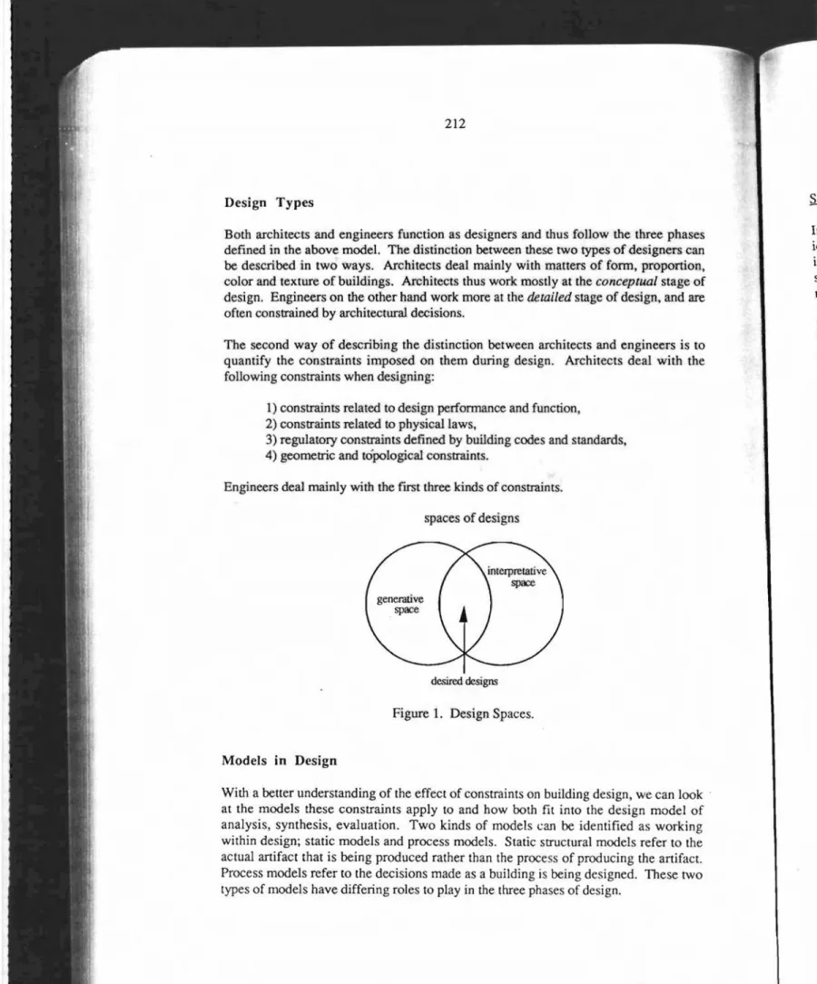
We can also characterize the above model of design as defining the search space of applicable designs. One part of this space as shown in Figure I represents all designs that can begenerated given some description such as a grammar that defines how components of
a
design may be configured together. The second space shown in Figure 1isinterpretativeand defines the set obtained by takinga design description, interpreting the lines drawn on a page as objects and mapping those objects to certain performances required of the design. Thus the desired designs produced by the above model are the intersection of all possible configurations for specified components of a design with all possible interpretations of a design description (Coyne et a!., 1990). That is, an intersection between all possible "correct" designs and all designs that result from a specified process of designgeneration. The idea of design spaces also has important implications for integration of computer based design systems with CAD programs. If designs produced with CAD programs are based on the same objects being interpreted for evaluation purposes then the two systems can be tied together and work seamlessly.Design Types
Both architects and engineers function as designers and thus follow the three phases defined in the above model. The distinction between these two types of designers can be described in two ways. Architects deal mainly with matters of form, proportion, color and texture of buildings. Architects thus work mostly at the conceptual stage of design. Engineers on the other hand work more at the detailed stage of design, and are often constrained by architectural decisions.
The second way of describing the distinction between architects and engineers is to quantify the constraints imposed on them during design. Architects deal with the following constraints when designing:
1)constraints related to design performance and function, 2) constraints related to physical laws,
3) regulatory constraints defined by building codes and standards, 4) geometric and topological constraints.
Engineers deal mainly with the 1ITSt three kinds of constraints. spaces of designs
desired designs
Figure1. Design Spaces.
Models in Design
With a better understanding of the effect of constraints on building design, we can look . at the models these constraints apply to and how both fit into the design model of analysis, synthesis, evaluation. Two kinds of models can be identified as working within design; static models and process models. Static structural models refer to the actual artifact that is being produced rather than the process of producing the artifact. Process models refer to the decisions made as a building is being designed. These two types of models have differing roles to play in the three phases of design.
Ie ii
il s'
Static Models ethree phases
.designers can
.n,Proportion,
?ptuaf stageof iesign, and are
ngineers is to jeal with the
:canlook model of working fer to the : artifact. hese two
In the Analysis phase of design, requirements are analyzed and building attributes identified. These attributes, such as building type, occupancy and use help to defme an initial model of the structure to be built. This general model can then be used to derive some of the constraints specifiedinbuilding codes and standards that apply and must be met.
In the Synthesis phase the initial model of the building tobe designed is further refined. This refinement process can again utilize models and constraints. One example of this is the use of prototypes to aid the synthesis process (Gero & Rosenman, 1989). The prototypes described by Gero and Rosenman represent variabalized models of structures or sub-structures and can be used to represent typical solutions to design problems. These prototypes may correspond to typical structural solutions for office buildings for example. Given a prototypical model, it is also possible to encapsulate within the model constraints that apply as specified in building regulations. For example, the structural prototype for apartments might contain constraints that relate bay sizes to floor systems. .
The Evaluation phase also utilizes models and constraints both for interpreting drawings and for performing the cOnformance checking process. If models of possible structures are extracted from building codes and regulations then these can be used to set up expectations of what objects may be found in a drawing. For example if a drawing represents a residential home then you would expect to fmd within the drawing certain rooms such as a kitchen, bathroom and bedroom. This knowledge can help determine the objects in a drawing if they are not already labelled. During the actual requirements checking process it will again be beneficial to use extracted building models to help classify objects to be checked. If these models and sub-models have constraints associated with them as was described above for synthesis, then only those constraints that apply to specific objects need be checked. This combination of models, constraints and classification will aid the evaluation process.
Process Models
Process models also exist within design and represent design actions taken and any decisions related to those actions. These models are quite different from static models and may contain for example, a sequence of decisions about the choice and application of various prototypes. Such models are important mainly in the synthesis phase, where they can be used to control an automated design process. In addition, having an understanding of these models can also allow for reuse of designs. Reuse corresponds to replaying a design history containing actions and decisions about actions to aid in the design of a new structure. Psychological studies have shown that reuse of past design histories can often result in better quality designs (Akin, 1988).
Having discussed the importance and possibility of utilizing models and constraints within the three design phases, the remainder of this paper will focus on the application of models and constraints to the evaluation phase. The models represent structures and sub-structures and the constraints represent the regulatory requirements present in building codes.
Models and regulatory constraints in evaluation of designs
In this section we will examine how representing a building regulation as a set of models and associated constraints can be used during the evaluation phase of the design cycle. Specifically we are concerned with checking a design for compliance with various building regulations. The regulation we have chosen to work with is the National Building Code of Canada (NBCC, 1985). It was chosen because it is a regulation that is produced by our Institute 1 and there is considerable local expertise in interpreting the document. We have concentrated on a particular section of the Building Code 2 , specifically the 15 sentences in the 1985 Building Code regulating the construction of flrewalls. This section was chosen as it was thought to be relatively simple in terms of its scope and the constraints it represents.
The compliance checking process
Building regulations impose constraints on designers in the form of performance requirements and prescriptive requirements. During the process of design a designer will have some knowledge of the constraints imposed by various building regulations on the problem. Usually this knowledge is a combination of general and specific rules that form part of the designer's experience. At the end of one of the design cycles a potential solution must be evaluated with respecttoappropriate regulations (in our case the Building Code). The evaluation process can be a complicated and time consuming task. Examining the compliance checking process will help us understand aspects of the evaluation phase of the design cycle.
A design can be considered as a system of assemblies, components, and materials. Constituent parts of a design may have predefined characteristics or attributes. Concrete, for example, is known to be a noncombustible material. A brick wall has been shown to have a 2 hour fire-resistance rating. This knowledge is generally known and forms part of the background information of the building domain. Other characteristics of a design must be derived. The simplest example of derived
I The Institute for Research in Construction, National Research Council of Canada. 2 The terms Building Code and Code shall referto the National Building Code of Canada. inf\ wit Co de: co' ho po de
cr;
E' al tc tt ilinformation about a building is the building area3. A design contains a set of objects with attributes and characteristics that are either known or derived (Coyne et al., 1990).
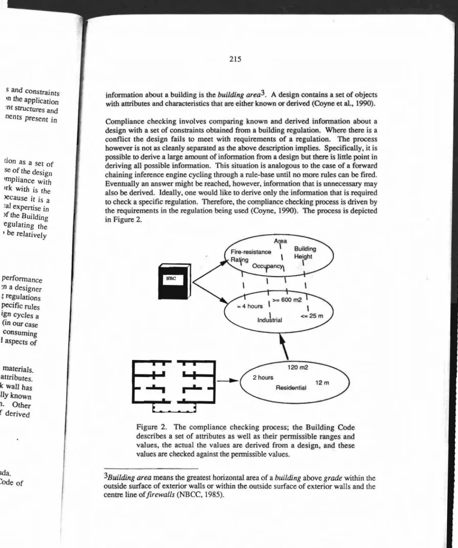
Compliance checking involves comparing known and derived information about a design with a set of constraints obtained from a building regulation. Where there is a conflict the design fails to meet with requirements of a regulation. The process however is not as cleanly separated as the above description implies. Specifically. it is possibletoderive a large amount of information from a design but there is little point in deriving all possible information. This situation is analogous to the case of a forward chaining inference engine cycling through a rule-base until no more rules can be fired. Eventually an answer might be reached, however, information that is unnecessary may also be derived. Ideally, one would like to derive only the information that is required to check a specific regulation. Therefore, the compliance checking process is driven by the requirements in the regulation being used (Coyne, 1990). The process is depicted in Figure 2. 120 m2 Residential
...,
tion as a set of se of the design lmpliance withIrk with is the Jecause it is a ;a]expertise in )f the BUilding egulating the • be relatively s and constraints mthe application 'nt structures and nems present in performance :n a designer セ regulations pecific rules ign cycles a (in our case consuming faspectsof materials. attributes. k wail has tllyknown n. Other f derived
Figure 2. The compliance checking process; the Building Code describes a set of attributes as well as their permissible ranges and values, the actual the values are derived from a design, and these values are checked against the pennissible values.
!ada.
COde of 3Building areameans the greatest horizontal area of a building above grade within the outside surface of exterior walls or within the outside surface of exterior walls and the centre line offirewalls (NBCC, 1985).
'Inorder to derive only the required information, it is important to notethata regulation is not simply a collection of constraints to be checked sequentially. Regulations are structured logically, typically in a hierarchical fashion from general to most specific. There is a considerable amount of ordering in the Building Code. The Building Code defines many attributes and characteristics that buildings may have. Most are dependent on or defined in terms of other properties. Because the requirements in building regulations will often be related, the derivation of certain attributes will be required out of necessity. For example, theBuilding Code maintains that all firewalls shall have a parapet (with specific exceptions of course) and the height shall be either 150 mm or 900 mm. The choice between the two is made on the basis of the required fire-resistance rating. The required fire-fire-resistance rating is determined by the type of occupancies on either side of the wall. In order to check a firewall for compliance with the parapet constraint the occupancy types must thus be known. These relations between attributes and characteristics in the Building Code can be represented as networks of dependencies. The graph below shows a partial dependency network for the attribute parapet_height.
Fire-resistance Rating
Ordering and dependency networks are reflected in the layout of the Building Code, the first portion of which is devoted to defining terms and classifying buildings.
Checking a design for compliance with a regulation can be done in two ways, top-down and bottom-up. A top-down approach to compliance checking involves deriving important characteristics of a design in order to satisfy certain high level constraints. For example occupancy and area would be needed to decide larger issues such as adjacency requirements or the requirement for sprinklers. Many specific constraints require knowledge of global characteristics of a design.
There are times however during compliance checking when a bottom-up approach is required. When checking for specific constraints only certain characteristics needbe
known. To determine the parapet height of a firewall only knowledge of the adjacent occupancy types is required. Dana Vanier (Vanier, 1991) has looked into the derivation of attributes and characteristics and their dependencies in the Building Code.
Ordering in a regulation allows the compliance checking process, whether top-down or bottom-up, to proceed in a logical, constrained fashion. This structuring however does not entirely solve the problem of the number of constraints to be checked. A regulation such as the Code contains 450 pages of rules and regulations governing the construction of buildings. A conservative estimate of the number of constraints contained in the code would be several thousand. To check a simple design against
t a regulation gulations are lost specific. Jilding Code re dependent in building required out shall have a ·150 mm or quired fire-the type of Jliance with ;e relations resented as letwork for •Code, the top-down deriving mstraints. s such as セョウエイ。ゥョエウ proach is ; need be adjacent erivation down or ver does gulation ing the straints against
several thousand constraints is clearly impractical. The solution is to restrict the number of constraints to be checked by eliminating those that are not applicable. If there is no infonnation about a design then the entire body of the regulation applies. As more information about a design becomes known, building area, for example, the set of applicable constraints becomes smaller. Classification allows us to narrow the range of applicable constraints. Classification is the act of arranging or distributing a concept or object into classes according to a method or system. Models, derived from a building regulation and background infonnation canbeused to classify designs.
How do models and constraints aid compliance」ィ・」ォゥョセ_
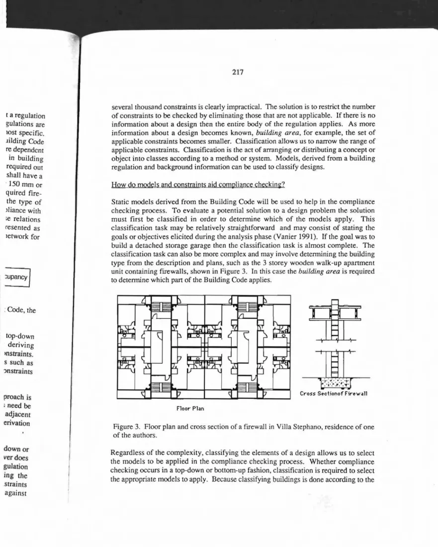
Static models derived from the Building Code willbe used to help in the compliance checking process. To evaluate a potential solution toa design problem the solution must first be classified in order to determine which of the models apply. This classification task may be relatively straightforward and may consist of stating the goals or objectives elicited during the analysis phase (Vanier 1991). If the goal was to build a detached storage garage then the classification task is almost complete. The classification task can also be more complex and may involve detennining the building type from the description and plans, such as the3 storey wooden walk-up apartment unit containing firewalls, shown in Figure 3. In this case thebuilding areais required to determine which part of the Building Code applies.
Cross Sectionof Firewall
Floor Plan
Figure 3. Floor plan and cross section of a firewall in Villa Stephano, residence of one of the authors.
Regardless of the complexity, classifying the elements of a design allows us to select the models to be applied in the compliance checking process. Whether compliance checking occurs in a top-down or bottom-up fashion, classification is required to select the appropriate models to apply. Because classifying buildings is done according to the
rules and definitions in the Building Code and the models are derived from knowledge in the Building Code, the comparison of designs with models is in effect classification.
The reason for selecting an appropriate model istogenerate a set of constraints to be applied to a given design, thus reducing the number of items to check. Models derived from the Building Code have constraints associated with them which are to a certain degree, encapsulated. For example, a model of a firewall carries with it a set of constraints. The firewall model is general in its nature but the constraints serve to limit its attributes or characteristics under specific conditions. BRANZ (Hamer, Hosking, & Mugridge, 1988) have developed a system where objects, such as walls, are completely encapsulated. As more knowledge about an object becomes known it can be reclassified and the applicable constraints updated.
Models allow us to write or derive information about a design. If we decide for example that a line on a drawing represents a firewall several things are understood. First, a model of a firewall has been associated with the line. Associating a model with a line on a drawing has the effect of generate a set of expectations or slots to ,be filled.
It may be possible to assign valueS to these slots from the design directly, or it may require that values be derived (such as the building area). The firewall model also tells us the following things:
1)it separates two buildings,
2)it represents a wall assembly,
3)the assembly has a fire-resistance rating,
4)the assembly is made of noncombustible materials,
5)the wall is made of concrete or masonry,
6)the wall extends continuously from the ground to roof,
7)the wall extends above the roof to form a parapet of a specified height,
8)the wall must be structurally stable for the fire-rated rime.
The model associated with the line also points to a set of constraints, pertaining to firewalls. Thus the firewall model, now associated with the line in the drawing, has the following constraints imposed on it:
1) The required fire-resistance rating for firewalls separating industrial occupancies is4hours,
2) The required fire-resistance rating for firewalls separating non-industrial occupancies is 2 hours,
3) The parapet height for a 4 hour firewall is 900 mm, 4) The parapet height for a 2 hour firewall is 150 mm,
5) The aggregate width of the openings within the firewall is limited to 25% of the length.
Once it is determined that a specific line represents a firewall certain data can be obtained directly from the design, specifically the length, height, and construction
details. constn: of: This c Build entiti canst regu] obje( Mod Buil reql! mad coni At, can not abc Co ext Me reI at sp Tl se
rom knowledge . classification. )nsrraints tobe \1odels derived lre to a certain lith it a set of s serve to limit セイL Hosking, & Irecompletely wn it Can be Ie decide for セ understood. a model with s tobefilled. Iy, or itmay
Idel also tells
ight, :rtaining to ng,hasthe industrial ·industrial :025%of a can
be
structiondetails. Other information, such as the fire-resistance rating, canbederived from the construction details. A task such as code checking is thus represented by the process of:
1) classifying the design in order to detennine the models that apply,
2)generating of a set of constraints by joining the constraints associated with the appropriate models,
3) testing the proposed design solution to ensure the solution satisfies the constraints (i.e. checking the actual values against the required values).
This corresponds to the process shown in Figure2.
What are Models and Constraints?
Building regulations such as the Building Code can beseparated into two conceptual entities. Models, which describe the objects that are the subject of the regulation and constraints, which limit the attributes and characteristics of the objects defined in a regulation. Constraints also place limits on the relationships that can hold between objects.
Models: What are they?
Building regulations are based on models in order to maintain the consistency of the requirements and the logical framework of the document. These models are rarely made explicit. A large part of our work has focussed on explicating the models contained in the Building Code (Cornick, Leishman, & Thomas, 1990).
At a high level of abstraction the Building Code canberepresentedasa collection of concepts and relations. Examples of concepts cover physical objects and more abstract notions such as health, and events. Relations tie concepts together. For example,
aboveis a relation that links two objects together. A regulation such as the Building Code defines a number of concepts unique to it as well as incorporating many concepts external to the document in the form of background information.
Models are represented as collections of concepts linked by relations, and can be
represented as a semantic network. Concepts can alsobethought ofasbeing ordered in a type hierarchy. A type hierarchy consists of concepts linked in order of increasing specialization. Therefore, the top of the hierarchy contains the most general concepts. This relation can be thought of as an
is_a
relation. Stating that a firewallis_a
fire-separation means that:1)it is a special kind of fire-separation,
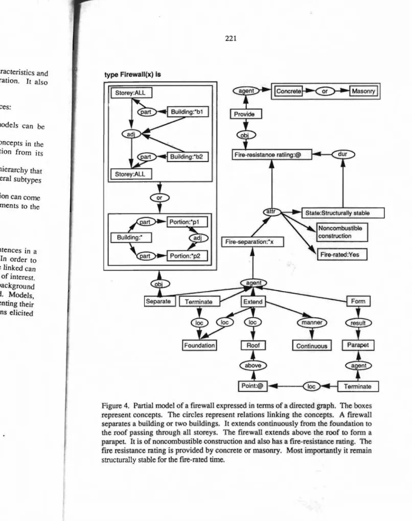
Amodel of a firewall is shown in Figure 4. The model consists of characteristics and attributes of a firewall that make it a specialization of a fire-separation. It also establishes expectations, such as the fact that it separates spaces.
Knowledge contained in models typically comes from the following sources:
1) Definitions - provided by the building regulation, models can be developed from definitions,
2) Supertypes - knowledge is inherited from more general concepts in the type hierarchy, for example a firewall inherits information from its supertype, fire-separation,
3) Subtypes - knowledge is derived from concepts in the type hierarchy that are more specialized, the at,tributes and characteristics of several subtypes maybegeneralized to form a model,
4) External and supplemental sources - this background information can come from the world or from explanatory material such as Supplements to the National Building Code or Commentaries.
Models: Creating them
The process of developing models involves interpreting each of the sentences in a regulation and representing them in terms of concepts and relations. In order to visualize the sentences, graphs showing how the concepts and relations are linked can be drawn. The graphs are created for each of the sentences in the section of interest. From these graphs, the Building Code (specifically the glossary), and background knowledge a type hierarchy of concepts and a list of relations is generated. Models, such as the firewall and fire-separation models are then generated by representing their definitions (obtained from the Code) in terms of the concepts and relations elicited earlier. The process is depicted in Figure 5.
f characteristics and separation. It also
sources:
n, models can be
ral concepts in the .rmation from its
ype hierarchy that
fseveral subtypes
rmation can come Ipplements to the
e sentences in a ns. In order to
ISare linked can セエゥッョ of interest. md background :rated. Models, presenting their セャ。エゥッョウ elicited 221 typeFirewall(x) Is I
i」ッョ」イ・エ・セ
セセッョイケ
I
State:Structurally stableFigure 4. Partial model of a fIrewall expressed in terms of a directed graph. The boxes represent concepts. The circles represent relations linking the concepts. A fIrewall separates a building or two buildings. It extends continuously from the foundation to the roof passing through aU storeys. The fIrewall extends above the roof to form a parapet It is of noncombustible construction and also has a fIre-resistance rating. The fIre resistance rating is provided by concrete or masonry. Most importantly it remain structurally stable for the flre-rated time.
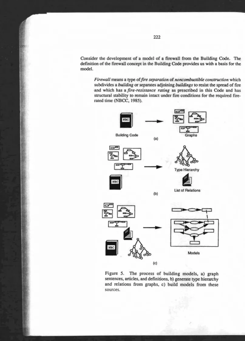
Figure 5. The process of building models, a) graph sentences, articles, and definitions, b) generate type hierarchy and relations from graphs, c) build models from these sources. Models
セ
Type Hierarchyf6J
List of Relations 1c::r""'1{eセ
It::rt I
Graphsセ
\II
..
Building Code (a) 1="'1{eセ
iセャ
セII
(b)10=1
{eiセii
l=-r
II..
セ
iiセ
(c)Firewall means a type ofjire separation of noncombustible constrzu:tion which
subdivides abuilding or separates adjoining buildings to resist the spread of fire
and which has afire-resistance rating as prescribed in this Code and has
structural stability to remain intact under fIre conditions for the required fire-rated time (NBCC, 1985).
Consider the development of a model of a firewall from the Building Code. The definition of the fIrewall concept in the Building Code provides us with a basis for the model.
lding Code. The
litha basis for the
Instructionwhich the spread of fire is Code and has -he required
fire-)
The graph in Figure 4 embodies most of the features of the definition, namely the fact that the wall has a fire-resistance rating, it is made of noncombustible materials, and must be stable. Other information comes from the regulations in the Code, specifically that the wall be constructed of masonry or concrete and that in general frrewalls have a parapet.
From the type hierarchy more information can be inherited. The attributes and characteristics of both fire-separations and wall assemblies are inherited by the firewall model. For example, a fire-separation may contain openings that must be protected. Consequently, frrewalls may contain openings that must be protected. The firewall model can be expanded to a considerable degree. For example, the model suggests that a firewall separates two buildings. The model of a building however states that buildings have a characteristic called major occupancy4. The frre-resistance rating and occupancy characteristics are related. The type of occupancies on either side of a firewall determines the required fire-resistance rating. Our models can inherit information either directly from the type hierarchy or indirectly by expanding their components.
Constraints
As mentioned above, we regard building regulations as being composed of models and constraints. The role of the models is to define and structure the domain of the regulation. Models, built from conceptsinthe type hierarchy and relations from the list of relations form the context to which the constraints in the Building Code will be applied. In a regulation such as the Building Code, constraints generally take the fonn of sentences that prescribe specific attributes or characteristics, specify certain performances of components and assemblies, or restrict the relationships between assemblies and components. Constraints thus have the effect of reducing the set of "correct" designs or generative space.
In compliance checking we are trying to solve a Boolean constraint satisfaction problem. Essentially there is a set of variables which must be instantiated in an associated domain, in our case the building domain. There is also a set of Boolean constraints limiting the set of allowed values for the variables (Mackworth, 1987). Constraints can take many forms, mathematical functions, free text, and rules. Generally constraintsinregulatory documents are expressed in the form of prescriptive requirements, concept X shall have attribute Y, or performance requirements, assembly Y shall have performance X. These types of constraints translate well into rules. Continuing with our firewall example, the 15 sentences in the Building Code provide the designer and plans examiner with limits on the characteristics of a frrewall. They
4Major occupancy means the principal occupancy for which a building or part thereof is used or
intendedtobe used, and shall be deemedtoinclude the subsidiary occupancies which are an integral part of the principal occupancy (NBCC, 1985).
specify what values characteristics and attributes must acquire given a specific context. For example Sentences (3) and (4) specify the fire-resistance rating of the wall. The model states that a frrewall is fire-rated and therefore has a fire-resistance rating. Sentences (3) and (4) specify the frre-rated time as it relates to the major occupancies of a building.
(3) Every required firewall which separates a building or buildings withfloor
areas containing a Group E or a Group F, Division 1 or 2 major occupancy shall
beconstructed as afire separation of noncombustible construction having
afire-resistance rating of at least 4 h, except that where the upper portion of afirewall
separates floor areas containing other than Group E or Group F, Division lor 2
major occupancies, the fire-resistance rating of the upper portion of the firewall
may be reduced to 2 h.
(4) Every required firewall which separates a building or buildings withfloor
areas containing major occupancies other than Group E or Group F, Division 1
or 2 shall be constructed as afire separation of noncombustible construction having afire-resistance rating of at least 2 h. (NBCC, 1985).
We have chosen to represent the constraints in the Building Code also as concepts and relations. In doing this our representation of models and constraints is consistent. A simplified graph of Sentence (3) is shown below in Figure 6a. The constraint is represented as a graph of the actual sentence in the regulation, however it could also be represented as a graph of a production rule (Figure 6b). The choice depends on the architecture of a particular compliance checking system and the type of reasoning used. Note that this constraint requires other information, namely the occupancy, that is not contained in the model of a firewall. Information such as this is inherited from other more abstract models as well as models linked to the firewall model through an aggregation relation.
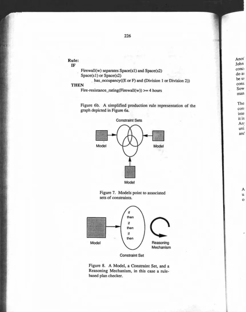
Given that the Building Code is divided into constraints and models it is possible to ask how they are related. Constraints can be linked to specific models derived from a building regulation as weIr as having a model point to a set. Figure 7 shows the later approach.
How constraints get used with models
Assuming that there exists a higher level system architecture for compliance checking, how would the constraints described above be applied to models? Given that the system has determined that a specific line represents a frrewall how would a system go about doing a compliance check using the constraints?
Using production rules, alluded to earlier, is one possible approach. Given that each model points to a set of constraints that are applicable a system might go through the entire associated rule set checking to see whether a constraint has been violated. If a
I I I I
I
Building'I
Building:·x IBuilding:.y Fire-resistance ratingII
Group Eセii
Group FI
I
U
Division 1 .セ
Division 2I
I
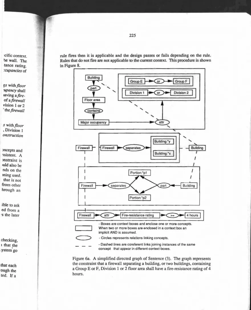
- Boxes are context boxes and enclose one or more concepts. When two or more boxes are enclosed in a context box an implicit AND is assumed.
- Circles represents relations linking concepts.
- Dashed lines are coreferenl links joining instances of the same concept that appear in different context boxes.
Firewall iMMMMMセ separates I'--...,...---J
I
Firewallt-I
I
I
I
Figure 6a. A simplifIed directed graph of Sentence(3). The graph represents the constraint that a firewall separating a building, or two buildings, containing a Group E or F, Division 1 or 2 floor area shall have a fire-resistance rating of 4 hours.
rule fIres then it is applicable and the design passes or fails depending on the rule. Rules that do not fIre are not applicable to the current context. This procedure is shown in Figure8. イMMMMMMMMMMMMMMMMMMMMMMMMMセM⦅L )ncepts and 1sistent. A mstraint is ,uldalso be nds on the ming used. that is not from other hrough an セウ with floor 'upancyshaH laving afire-ofafirewall vision lor 2 'thefirewall :cific Context. he wall. The tance rating. Xupanciesof swith floor , Division I onstruction ible to ask ed from a 's the later checking, I that the ;ystem go that each ough the ted. If a
u. o A The can: inte it is An: uni
anc
Anal' John cone, doal beオセ cons Sowman
Reasoning Mechanism Constraint Set Model Constraint SetsFigure 7. Models point to associated sets of constraints.
Figure 8. A Model, a Constraint Set, and a Reasoning Mechanism, in this case a rule-based plan checker.
Firewall(w) separates Space(sl) and Space(s2) Space(sl) or Space(s2)
has_occupancy«E or F) and (Division 1 or Division 2))
Figure 6b. A simplified production rule representation of the graph depicted in Figure 6a.
THEN
Fire-resistance_rating(Firewall(w)) >= 4 hours
Rule: IF
u1':
1) the relations linking the concepts in u' and v are identical,
2) the concepts in u' are identical or specializations of the concepts in v,
3) if a relation links two concepts in v then it also links the corresponding concepts in u'.
u2':
v:
u2:
Another approach would be to use some of the conceptual graph operations defined by John Sowa (Sowa, 1984). Although representing a building regulation as a set of concepts and relations seems to be a good approach, the representation is too abstract to do any useful work. To provide structure and reasoning power conceptual graphs can be used to represent the models and constraints. The type hierarchy, relations, models, constraints, and graphs are essentially the same as before.
Sowa's conceptual graphs merely provide us with systematic ways of constructing and manipulating these expressions while enforcing selectional constraints.
u1 :
The conceptual graph model defines specialization operations used for selectional constraints and generalization operations for logic and model theory. Of particular interest here are the generalization operations. If two conceptual graphs are compared, it is possible to describe a common generalization of the two graphs.
Any two graphs will always have a least one common generalization, namely[T],the universal graph, since it is a generalization of all graphs. Consider the two graphs u I and u2 and their common generalization v.
Another graph operation of interest is the projection operator. Given two graphs v and u, if v is the more general of the two, Le. v is a generalization of u, then the projection operation consists of fmding a subgraph u' in u subject to the following conditions:
The projection of the graph v into ul and u2 is then: of the
Ir et 1 p o f, t In en is Me apf unt cor tWI D In S1 Sine wit! agaJ Thi bee Thes betW( knO\\ same conIC com) Code to pr Common generalization Projection of common generalization into model condition
if required1=value then fail セ
...
_ - - - - 'Model
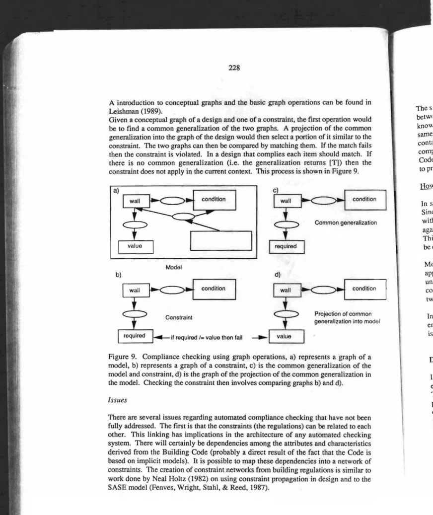
Figure 9. Compliance checking using graph operations. a) represents a graph of a model, b) represents a graph of a constraint,c) is the common generalization of the model and constraint, d) is the graph of the projection of the common generalization in the model. Checking the constraint then involves comparing graphs b) and d).
A introduction to conceptual graphs and the basic graph operations can be found in Leishman (1989).
Given a conceptual graph of a design and one of a constraint. the first operation would beto find a common generalization of the two graphs. A projection of the common generalization into the graph of the design would then select a portion of it similar to the constraint. The two graphs can then be compared by matching them. If the match fails then the constraint is violated. In a design that complies each item should match. If there is no common generalization (Le. the generalization returns [T]) then the constraint does not apply in the current context. This process is shown in Figure 9.
Issues
There are several issues regarding automated compliance checking that have not been fully addressed. The first is that the constraints (the regulations) can be related to each other. This linking has implications in the architecture of any automated checking system. There will certainly be dependencies among the attributes and characteristics derived from the Building Code (probably a direct result of the fact that the Code is based on implicit models). It is possible to map these dependencies into a network of constraints. The creation of constraint networks from building regulations is similar to work done by Neal Holtz (1982) on using constraint propagation in design and to the SASE model (Fenves, Wright, Stahl.& Reed, 1987).
ns can be found in
...stoperationwould
on of the common 1of itsimilarto the
. IIthe match fails
1should match. If irns [TJ) then the
vn in Figure 9.
;ommon generalization
)jectionof common 1eralization into model
Its a graph of a "alization of the eneralization in md d).
: have not been
related to each Jated checking characteristics at the Code is ) a network of ·1Sis similar to ign andtothe
The second issue is where should thisknowledgereside given the conceptual separation between models and constraints? One approach is to encapsulate all the appropriate knowledge in the model and constraint sets. Thus several models might point to the same constraint (as shown in Figure 7 above). The constraint dependencies would be contained in the constraint sets. This approach seems to lend itself to rule-based compliance checking. Another approach might be to represent the logic of the Building Code separately from the models and constraints. This knowledge would describe how to propagate the constraints.
How are models and Constraints Useful?
In summary, models and constraints are useful in the compliance checking process. Since the models are derived from the Building Code they help in classifying designs with respect to the Building Code by providing a template or frame to match the design against. They are useful in that once a match is made a set of expectations is generated. This can be as simple as a set of slots to be filled in or it may represent information to be derived about a design and checked against performance criteria.
Models also provide us with access to layers of inherited information. In a bottom-up approach to compliance .checking a model can be expanded, by substituting supertypes, until the required information becomes known. This is a sort of back propagation of constraints (e.g. iftheparapet is 150 mm then the required fire-resistance rating must be two hours therefore the building contains no occupancies of type E or F).
In a top-down approach the models and their associated constraints serve to generate an envelope within which the remaining, more specialized models must lie. In effect this is the same as classification.
Discussion
In this paper we have outlined the broader issues relating the design process, as envisaged within the construction industry, to computerized support for such activities. The major thrust in this paper has focused upon the evaluation phase of the design process (Asimow 1962) with the description of a system based upon an existing body of reguiatory codes (NBCC 1985). Within this approach we have identified the need for both Static and Process models along with their associated constraints imposed by both the regulatory documents and the Users objectives.
The derivation of the static models from theregulatorycodes has notonlyprovided us with a dearer understanding of the implicitmodelscontained within the code documents but has also pointed areas of confusion within the documents themselves. By separating the models from the constraints imposed by the codes we hope to provide a system which can be adapted to changes in the regulations by changing the constraints
on the models rather than having to make changes to the models themselves. Over time, the models contained in regulatory codes are stable and the changes that do OCcur are generally associated with constraints on the models. The next step in our research programme is the integration of this system with CAD and an associated object oriented database.
References
Akin, O. (1988). Expenise of the Architect. In M. D. Rychener (Ed.),Expert Systems for Engineering Design (pp. 173-196). San Diego, CA: Academic Press, Inc.
Asimow, W. (1962).IntroductiontoDesign. Englewood Cliffs, New Jersey:
Prentice-Hall. .'
Cornick, S. M., Leishman D. A., & Thomas, J. R. (1990). The Integration of Regulatory Codes with Design Systems. In A. Gulliver (Ed.),Canadian Conference on Electrical and Computer Engineering: Ten Years to 2000,1 (pp. 14.4.1-14.4.5).
Ottawa, Ontario: Canadian Society for Electrical and Computer Engineering. Sept. 4-6.
Coyne, R. (1990). Logic of Design Actions.Knowledge-Based Systems,
3(4),242-257.
Coyne, R. D., Roseman, M. A., Radford, A. D., Balachandran, M., & Gero, J. S.
(1990).Knowledge-Based Design Systems. Sydney, Australia: Addison-Wesley.
Fenves, S. J., Wright, R. N., Stahl, F. t, & Reed, K. A. (1987). Introduction to
SASE: Standards Analysis, Synthesis, and Expression No. NBSIR 87-3513). National Bureau of Standards, U.S. Department of Commerce.
Gero, J. S., & Rosenman, M. A. (1989). A Conceptual Framework for Knowledge-Based Design Research at Sydney University's Design Computing Unit. In J. S. Gero (Ed.),Artificial Intelligence in Design, 1 (pp. 363-382). Cambridge, UK: Computional
Mechanics Publications/Springer-Verlag. July.
Hamer, J., Hosking, J. G., & Mugridge, W. B. (1988). The Evolution of Class Language No. 75 Building Research Association of New Zealand.
Holtz, N. M. (1982) Symbolic Manipulation of Design Constraints. PhD. Thesis,
Department of Civil Engineering, Carnegie-Mellon University.
Leishman, D.A.(1989)A Principled Analogical Tool. Masters Thesis, Department of
Computer Science, University of Calgary.
Mad
Ency' Wile The Rese Sow Mac Van Bui] Junl at all Ie rc
hemse1ves. Over n.ges that do occur ep in our research
edobject oriented
Mackworth, A. K. (1987). Constraint Satisfaction. In S. C. Shapiro (Ed.),
Encyclopedia of Artifidallntelligence (pp. 205-211). New York, New York: John
Wiley & Sons.
The National Building Code of Canada. (1985), Ottawa Ontario Canada: National Research Council of Canada.
ZZZZセGッセ」]]^MMMMゥャ
Station matr altr agentセaイイゥカ・
セ
Quick II agentI
Ambulance: #r--Sowa, J. F. (984). Conceptual Structures: Information Processing in Mind and
Machine. Don Mills, Ontario: Addison-Wesley.
Vanier, D. J. (1991). A Parsimonious Classification SystemtoExtract Project-Specific Building Codes. To appear in Computers and Building Standards. Espoo, Finland. June 8-15.
Appendix A. The type hierarchy and relations
The following are definitions of relations used to link concepts. They are taken from Sowa p. 415 (1984).
agent. (AGENT) links [ACT] to [ENTITY], where the ENTITY concept represents the actor of the action. Example: Eve bit an apple.
attribute. (ATTRIBUTE) links [ENTITY:*x] to [ENTITY:*y] where *x has the attribute *y. Example: The rose is red.
location. (LOC) links a[T]to a [PLACE]. Example: Vehicles arriveata station.
manner. (MANNER) links an [ACT] to an [ATTRIBUTE]. Example: The ambulance arrived quickly.
material. (MATR) links an [ACT] to a [SUBSTANCE] used in the process. Example: The gun was carved out of soap.
: Integration of n Conference on 14.4.1-14.4.5). セイゥョァN Sept. 4-6. PhD. Thesis, ems, 3(4), 242-Jersey: Prentice-, & GeroPrentice-, J. S. I-Wesley. If Know1edge-t.In J.S.Gero ; Computiona1 " Expert Systems
:ss,
Inc. )epartment of tion of Class "ltroduction to aR 87-3513).The cat swallowed the canary.
part. (PART) links an [ENTITY:*x] to an [ENTITY:*y] where *y is a pan of *x. Example: A finger is part of a hand.
Construe! Fire-resistan rating Fire Combus Construe
--ApertureI
F Opening Constro Bui / Fire-separa'"
Canary: #
I
e *y is a part of *x.
Universal
A
G「OMセe
. E - S_ tln ute セ vent tate
」ッョウエイucャ・、セセ
セ
iセ
.
Fire-resistance Act Pass Reaction
rating / \ .
I
Fire-rated Create Prevent Chemical
Reaction Construction Through
I
7""
Combustible Noncombustible Construction Construction Fire safety Fire Parapet Mobile entity/1""-Flame
PhysObj Space Stationary entity Substance-Time
\
I
/"'..
/"-Heat Smoke Artifact Area Place Barrier Material Water
セO
\セセッッイ。イ・。
Maso:;セイ・エ・
AsserblYセ Djice Structre
Construction assembly Closure Building
I
Aperture
I
Opening
bセNLLLュ「iy
Fire-separation Wall assembly
セO
Appendix B. Models
This appendix contains the model of a fire-separation as well as some of the models on which it is based.
1. A fire-separation means a construction assembly that acts as a barrier against the spread of fire (Shaded boxes represent information that has been inherited from other models) (NBCC, 1985). Through, Fire-resistance rating:@ IFire-rated{yeslno} . Construction Type
Fire separation means a construction assembly that acts as a barrier against the spread of fire. Shaded boxes represent information inherited from other types.
2. Arti 3. Cc 4. A 5. ( safe 6. cc ra
orne of the models on
. a barrier against the inherited from other
2. Artifactn. An object produced or shaped by human workmanship. type Artifact(x) is
セ
eョエセケサp・イウッョャm。」ィゥョ・ス
I
3. Componentn. A simple part. or a relatively complex entity regarded as a part. type Component{x) is
I
Artifact'x4. Assemblyn. A set of manufactured parts (components). type Assembly{x) is
I
Artifact'xセ
Components{'y}5. Construction assembly. n. An assembly that is constructed. has a degree of fire safety. and has a construction type.
6. Building assembly. n. A building assembly is a construction assembly that
constitutes part of a building, it maybefire-rated. and it may have a fire-resistance rating. type Construction-assembly(x) is Fire-resistance rating:@ type Building-assembly(x) Is cッョセエイオ」エゥッョM。ウウ・ュ「ャケ :'x Assembly:'x
セオイ・j
•7. Preventv. To keep from happening, as by some prior action.
typePrevent(x) is
セセeカ・ョエャAQ
8. Passv. To run; extend, to move on or ahead.
type Pass(x) is
9. Barriern. Anything, material or immaterial, that acts to obstruct or prevent passage.
type Barrier(x) is