Publisher’s version / Version de l'éditeur:
Vous avez des questions? Nous pouvons vous aider. Pour communiquer directement avec un auteur, consultez la première page de la revue dans laquelle son article a été publié afin de trouver ses coordonnées. Si vous n’arrivez pas à les repérer, communiquez avec nous à [email protected].
Questions? Contact the NRC Publications Archive team at
[email protected]. If you wish to email the authors directly, please see the first page of the publication for their contact information.
https://publications-cnrc.canada.ca/fra/droits
L’accès à ce site Web et l’utilisation de son contenu sont assujettis aux conditions présentées dans le site LISEZ CES CONDITIONS ATTENTIVEMENT AVANT D’UTILISER CE SITE WEB.
2nd Conference and Workshop on Nanotechnology in Petroleum Industry [Proceedings], pp. 1-173, 2004-10-11
READ THESE TERMS AND CONDITIONS CAREFULLY BEFORE USING THIS WEBSITE.
https://nrc-publications.canada.ca/eng/copyright
NRC Publications Archive Record / Notice des Archives des publications du CNRC : https://nrc-publications.canada.ca/eng/view/object/?id=21897b78-3fb1-44fc-9cee-1f6775acaa53 https://publications-cnrc.canada.ca/fra/voir/objet/?id=21897b78-3fb1-44fc-9cee-1f6775acaa53
NRC Publications Archive
Archives des publications du CNRC
This publication could be one of several versions: author’s original, accepted manuscript or the publisher’s version. / La version de cette publication peut être l’une des suivantes : la version prépublication de l’auteur, la version acceptée du manuscrit ou la version de l’éditeur.
Access and use of this website and the material on it are subject to the Terms and Conditions set forth at
PNC polymeric nanocomposites: fundamentals & technology
PNC
Polymeric
Nanocomposites:
fundamentals & technology
L. A. Utracki
NRCC/IMI, 75 de Mortagne, Boucherville, QC, Canada J4B 6Y4; Tel.: +1 (450) 641-5182; fax: -5105
2nd Conference on Nanotechnology in Petroleum Industry, Teheran, 2004.10.11-10; Workshop lecture.
2
Outline
Introduction
Polymeric nanocomposites (PNC)
Applications Diversity of PNC’sClay and its intercalation & exfoliation methods
Fundamentals
Mathematical modeling Thermodynamics of PNC Rheology of PNC
Performance (mechanical, barrier, flammability)
Production of CPNC
IntercalationReactive exfoliation
Melt exfoliation in shear flow
Melt exfoliation in elongational flow
Conclusions
Plastics production in 2005:
184 million tons
US $700 billion
0.01 0.1 1 10 100 1000 1900 1940 1980 20201900-2010 world production of plastics (Mton)
production data sigmoidal fit Pl a st ic s pro du ct ion ( M to n) Year WP = 0.14151 + (2*0.042959/ )* tan-1((Year - 1947.262)/17.881) R = 0.99489
Annually produced
volume of plastics
is sufficient to:
Form a circular rod with diameter:
D = 76.5 m
all along Equator, or
Cover Iran with a
plastics sheet
h = 112 mm
thick.
4
Nanocomposites (NC) = matrix + dispersed in it nanometer-size
particles.
The matrix may be single- or multi-phase.
It may comprise additives that complement functionalities of the
system (reinforcement, electrical conductivity, toughness, etc.)
Depending on the nature of matrix, NC is:
Polymeric NC (PNC)
Ceramic NC (CNC) Metallic NC (MNC)
To generate high enhancement of properties, the nano-particles
ought to be anisometric, viz.
lamellar
, fibrillar, tubular, etc.
Spherical particles have been used to produce functional NC
(e.g., for electrical conductivity, optical or magnetic properties).
The reinforcing effects of nano-particles is related to the
particle-matrix interactions and aspect ratio, p:
For p > 500 the reinforcing effect is the same as of an infinitely large particle.
Since the absolute size of the reinforcement is not important, a small amount of nano-particles has a disproportionably large effect.
Because of small size, the nano-particles are invisible to the
naked eye and their surface energy is high. Hence, they may be
used to engender reinforced, but transparent composites.
In the absence of antagonistic interactions (e.g., hydrophilic
nano-particles in hydrophilic matrix) they do not require the interface
modification.
NC normally requires 1-2 vol% (or 6 wt%) of nano-particles,
behaving as a single phase and single component material
– it is
transparent and easily modified by additives.
6
Introduction 4
The most common PNC types are:
Clay-containing polymeric nanocomposites (
CPNC
) contain a layered material, mineral or synthetic clay, viz. montmorillonite (MMT),vermiculite, synthetic fluoromica (FM) or hectorite. Especially MMT is of commercial interest.
Polyhedral oligomeric silsesquioxanes – POSS.
Prepared by a sol-gel method that leads to spherical, functional
particles.
Several plastics producing companies are involved in the development and production of PNC, viz. Honeywell, Bayer, BASF, Dow Plastics, DuPont/ICI,
Eastman, GM, Magna Intl., Mitsubishi, Montell, RTP Co., Showa Denko, Solutia, Toyota, Ube, Unitica, etc. Nanocor is focused on the CPNC technology.
By the year 2020 the world production of PNC is expected to reach 30 Mton/year worth over US$65 billion.
Clays Advantages Disadvantages
Mineral Traditional technology
Availability
Cost (in 2001 US$1,600/ton)
Variability of composition
Difficulty in removing amorphous
Poor reproducibility in PNC performance
Synthetic Control of composition High aspect ratio p 2000
Reproducible PNC performance
Developing technology Limited sourcing
Cost (in 2001 US$2,300/ton)
Question whether natural or synthetic clay is to be used has not been settled:
CPNC show improved properties, viz.
Mechanical (2-5 x modulus, strength and thermal expansion), resulting in reduced wall thickness
Barrier, HDT, Transparency, surface finish, etc., hence reduced molding cycle time
Flammability, low density, modification of matrix crystallinity, relative isotropicity.
Introduction 5
8
Diversity of PNC 1
Examples of commercially important NC with polymeric matrix.
Matrix Nano-particles Properties Application
Polyamide (Nylon), esp. poly-e-caprolactam (PA-6)
Major players: Toyota, AlliedSignal, Ube, Nanocor, Unitica, Showa Denko, Bayer, BASF, Solutia-Dow
Delaminated (or exfoliated) silicates, e.g., montmorillonite; 1-2 vol%. Exfoliation is critical, done either by a monomer or selected solvent.
In comparison to PA: similar density, transparency, 70oC higher heat deflection temperature, 70% higher tensile modulus, 130% higher flexural modulus, 1/2 lower oxygen
permeability, 70% lower flammability, etc.
Automotive (e.g., truck mirror housing, engine covers), tool housing, garden equipment, telecommunication,
aerospace, specialty application, barrier film for food packaging, etc.
Polyolefins, viz. polypropylene (PP) and its copolymers)
Major players: Montell, GM, Southern Clay Products Inc., Toyota, Ford, Dow Plastics, Magna International
Exfoliated smectite clay particles; 5 wt%. Compatibilizer is needed for these hydrophilic clay hydrophobic PO systems. For example, Toyota uses maleic anhydride modified PP
Low density (0.91 g/mL) with high stiffness (equivalent to standard composites with 35 wt% talc), dimensional stability, low temperature impact strength, ductility to –35o
C, high heat aging, 75% lower flammability, excellent surface finish
Automotive: body panels, door panels, interior trim, instrument panels, pillars, consoles, etc.
Polystyrene (PS) and its blends with poly(styrene-co-vinlylmethyloxazoline) Major players: Toyota
Surface-treated clay particles; 4.8 wt%. High strength, tensile modulus increased by 37 % (over PS matrix), 43% smaller thermal expansion
Aerospace, automotive Polyethyleneterephthalate (PET)
Major players: Eastman, Bayer, BASF
Solution-expanded clay particles present during the polycondensation reaction
Transparency, low permeability, high strength, high stiffness, low density NC to be the central layer in co-formed products.
Food packaging, esp. as bottles for beer, juice and soft drink
Ethylene-vinyl alcohol copolymer (EVAl)
Major players: Nanocor, Mitsubishi
Exfoliated smectite clay particles; 5 wt%.
NC to be the central layer in multilayer, co-formed products
Packaging films, for moisture and oxygen sensitive foods and electronics Polyoxymethylene or acetal (POM)
Major players: Showa Denko, Bayer
Montmorillonite (?) Low warpage, low shrink, high surface quality, heat deflection temperature increased by 45o, 40% higher modulus
Automotive under-hood applications, electronics, etc.
Polyolefins (PO)
Major players: Toyota, Mitsui, Showa Denko, Mitsubishi
Nano-particles: Clays (e.g., MMT or vermiculite having the aspect
ratio p = 10 to 1000 or 1,000 to 15,000, respectively); synthetic
silanes (fluoromica, hectorite, tetra-ethoxysilane, POSS, SiO
2);
mineral salts (e.g., CuS, ZrO
2, Fe
2O
3, TiO
2, V
2O
5, Ag or Au); rigid
polymers (cellulosic whiskers, LCP, carbon nanotubes), etc.
Any polymer: viz. PE, PP, PS, PMMA, ionomers, PVE, PEG, PVP,
polypyrrole, SMA, PCL, PVAc, P(tBuA); PA-6, PET, PC, epoxy,
PDMS, dendrimers, polyaniline, polyacrylamide, lattices, LCP, etc.
Preparation, general:
Polymerization (any reaction in any medium). Dispersion in solvents
Melt compounding with organoclay; in TSE or internal mixer.
Diverse (complexing and immobilization of dendrimers with (CuS)15,; sol-gel processing; solvent casting; electrochemical preparation of conductive NC), etc.
Strong effects of processing on performance!
10
Applications of CPNC’s
Unitica produces injection-molding grades of PA-6 based PNC used for production of car engine and converter covers for Mitsubishi & Toyota.
The same grade is also used for injection molding of highly rigid bases for the electronic control tray & cover.
Ube PNC is used for rear mirror and timing belt housing.
Bayer PA-6 based PNC for barrier film packaging.
Eastman Chem. and Nanocor used MDX-based PNC as an inner layer in PNC bottles to control permeability.
Kabelwerk Eupen: EVAc/organoclay for wire & cable. Drastic reduction of heat release at 3 to 5 wt% clay.
Showa Denko: PA-66 and POM based PNC’s for flame retardancy and rigidity at 0.4 mm thickness. The flex moduli are 30-80% higher, and HDT 30 to 80°C higher, than those of neat resins.
TPO Nanocomposites
4 years of collaboration of GM, Basell, Southern Clay Products, and
Blackhawk Automotive Plastics, resulted in introduction of PP with 2.5% MMT ―step-assist‖ for 2002 GMC Safari and Chevrolet Astro vans. The key to success is reactive exfoliation of MMT during polymerization [Modern Plastics, Oct. 2001].
By 2004 GMC expanded the use of CPNC to body side moldings
(Chevrolet Impala-2004) and load floor panels (Hummer H2 SUT).
12
Gasoline tank
Other applications of CPNC’s
PET
The two bottles after hot
filling with water at 95
oC,
closed and reopened
PET + 3% organoclay
Definitions
Exfoliated clay:
− individual
platelets dispersed in a matrix
with spacing d
001> 8.8 nm.
The platelets may form Short
stacks randomly dispersed.
Intercalated clay:
− having
organic or inorganic molecules
inserted between Platelets, thus
with d
001> 1.5 nm.
Intercalant:
− material sorbed between Platelets that binds with their
surfaces to form an Intercalate.
Interlayer, basal spacing or d-spacing, d
001is the thickness of the
repeating layers as seen by the XRD = mineral thickness
14
TEM of CPNC
HDPE melt compounded with intercalated clay (A)
HDPE polymerized onto the intercalated clay (B). Noteworthy, clay
reduced catalyst activity by ca. 100.
PNC performance of LLDPE > that of HDPE
[Heinemann et al.,1999].
Epoxy PNC (C) shows a better, but still not total exfoliation of MMT
[Giannelis, 1996]
.
X-ray diffraction
XRD is used to determine:
The mean interlayer spacing, d001 (Bragg)
The number of platelets per stack (Scherer)
The relative amount of clay platelets in stacks and these exfoliated. Left Fig.: A = MMT intercalated with di-methyl-stearyl-benzyl
ammonium chloride; B = HDPE melt compounded with A; C = HDPE polymerized on A; D = HDPE [Heinemann et al., 1999].
Right Fig.: A = intercalated MMT; B = LLDPE melt compounded with A; C = LLDPE polymerized on A (LLDPE = polyethylene-co-octene).
16 0 2 4 6 8 10 RT = 62.7sec RT = 96.0sec RT = 148.5sec RT = 168.7sec RT = 228.6sec RT = 405.5sec In te n s it y 2
The 1
stpeak area decreases with increase of the residence time
(RT), while that of the 2
ndpeak increases due to re-aggregation.
Organoclay: 5 wt%
Barrel temp.: 200°C
Screw: high shear
Increase
of RT
0 5000 1 104 1.5 104 2 104 2.5 104 3 104 3.5 104 0 2 4 6 8 10 Int en si ty ( cps ) 2*Theta A 1 A 2Definition of peak areas
Organoclay d-spacing
XRD of PA-6 with C15A
Interlayer spacing d001 (nm) N Platelets/stack C15 wt% Specimen(EFM gap) Main peak Secondary peak Main peak Secondary peak XE; % Exfoliation 100 Cloisite 15A 3.21 1.95/1.22 3.34 3.23 - 4 Master-batch 4% 3.87 1.91 3.35 4.75 - 4 Stabilized master-batch 4% 3.93 1.92 3.40 5.31 10.4 4 TSE 3.97 1.94 3.16 4.87 20.6 4 TSE+GP 3.90 1.91 3.28 4.86 17.7 2 TSE 4.44 1.98 2.79 4.21 52.7 2 TSE+GP 4.42 2.02 2.89 3.80 64.7 4 (1000) 3.96 1.95 3.08 4.57 19.4 4 (250) 3.91 1.92 3.35 4.96 8.9 4 (60) 4.11 1.98 3.16 4.88 10.4 4 (30) 3.97 1.93 3.29 5.30 10.1 4 (5) 4.25 1.995 2.82 4.50 27.0 2 (1000) 4.26 2.02 2.92 4.20 56.1 2 (250) 4.30 2.04 2.86 4.16 60.8 2 (60) 4.36 2.06 2.83 4.02 65.4 2 (30) 5.29 2.00 2.83 4.84 76.0 2 (5) 4.39 1.94 2.78 2.53 83.3
d001 decreases from 3.2 to 4.0 in 4% PNC, and to 4.3 - 5.3 nm in 2% PNC. The number of clay platelet per stack is ca. 3 for all.
The degree of exfoliation ranges from 10 in MB to 83% in EFM-compound!
1 2 001 peak height hkl t 0.9 N 1 ; t d W cos l
1
0
100
A
A
X
E
Bragg:
Scherer
:
Exfoliation %:
00 n 001d
n /( 2 sin )
d
8.8253 / 2 ( nm )
l
18
Methods of CPNC preparation
The three principal
methods for CPNC
preparation are:
1. REACTIVE (in situ
polymerization)
2. SOLUTION (dispersing
organoclay in polymer
solution)
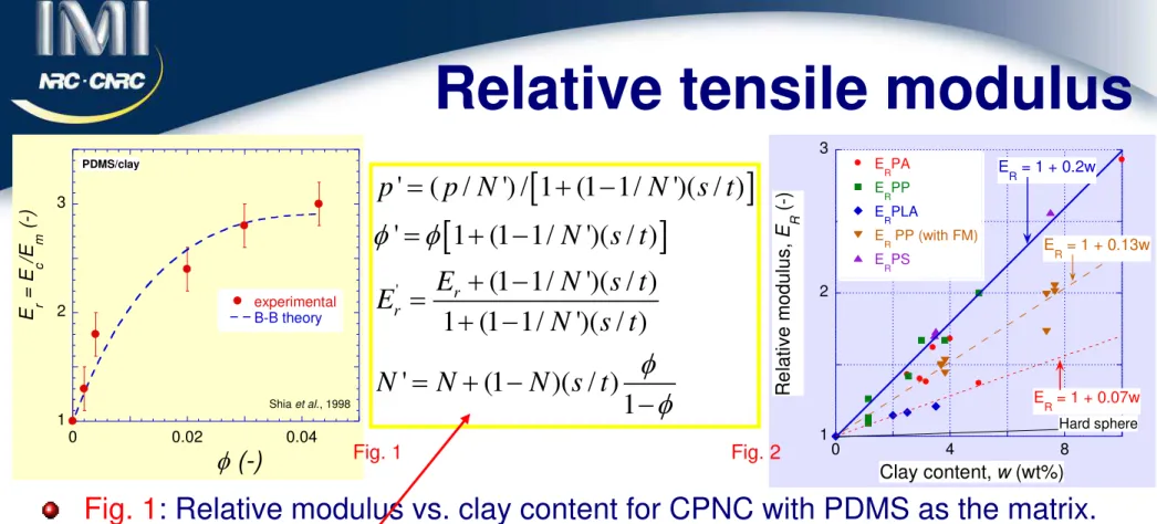
PNC Performance
4 main reasons for the development of PNC:
Enhanced rigidity (100% at 5 wt% clay)
Improved barrier properties (by a factor of 100 at 10 wt%) Reduced flammability (PHRR reduced by 2/3 at 5 wt% clay)
Improved heat deflection temperature (HDT)
Examples of published data for various systems are
tabulated for PA-
6 and its CPNC’s with 2 wt% organoclay:
Mechanical properties of PA-6 and based on it PNC.
Data from [Ube Industries, Ltd., 2002, and Unitika Plastics, 2004].
Property ASTM Units Ube Unitika
PA-6 PNC PA-6 PNC Tensile strength, D-638 kg/cm2 800 910 810 930 Tensile elongation, eb D-638 % 100 75 100 4 Flexural strength, f D-790 kg/cm 2 1100 1390 1080 1580 Flexural modulus, Ef D-790 kg/cm2 28,500 35,900 29,000 45,000
Impact strength, NIRT D-256 kg cm/cm
6.5 5 4.9 4.5
HTD (18.56 kg/cm2) D-648 oC 75 140 70 172 HTD (4.6 kg/cm2) D-648 oC 180 197 175 193 H2O permeability, PH2O JIS Z208 G/m2 24
h
203 106 -- --
Both companies use reactive
exfoliation.
Ube starts with MMT/ODA
Unitika uses
synthetic clay for reproducibility & color control.
20
Clays 1
Clays are classified as
:
Crystalline: kaolin's, serpentines, smectites, vermiculites, micas, etc. Amorphous: allophane, imogolities, hydrated alumina, ...
Crystalline clays are layered, with large specific surface area, esp. for d 2 mm. Clays are chemically complex, with properties that change from one deposit layer to another.
At T < 500°C smectites (e.g., montmorillonite, MMT) are composed of 4 layers:
Three-layer, 0.956 nm thick sandwich: octahedral central with excess charge, and two tetrahedral: SiO2-(Al/Mg)-SiO2, with negative charges and –OH groups on the surfaces and edges.
Water absorbing, expandable (by H2O, alcohols, glycol, glycerol, etc.) layer with charge compensating Na+, K+, Ca++, Mg++ ions.
Clay uses: for bonding (sand), catalysis, water clarification; in ceramics, drilling fluids, oil refining and decolorization, paper-making, viscosity controllers in motor oils, greases, adhesives, paints, cosmetics, pharmaceuticals, polymers, etc.
In polymers clays have been used as fillers, thermoset h-controllers, nano-reinforcer's, etc.
Clays 2
Clay (MMT) contaminants are: silica, feldspar, gypsum, orthoclase, apatite, halite, dolomite, muscovite, pyrite, etc. Ca-MMT content is > 50 wt%.
Purification: grounding to < 200 mm, dispersing to 10 –15 wt%, sedimenting, hydrocycling to remove impurities of d > 50 mm, and amorphous clay.
The resulting suspension that contains
3-7 wt% of MMT (d = 5-10 mm) is cation exchanged, giving > 95 wt% Na-MMT.
Centrifugation removes d > 5 mm particles, filtration to 12 wt% solids, spray drying to powder with 9 wt% H2O.
Product is then conveyed to holding tanks, then to the bagging area.
22 Cell unit MW (g/mol.) 540.46
Density (g/mL) 2.3 to 3.0 Mohs Hardness @20°C 1.5- 2.0
Cleavage Perfect in one direction, lamellar Characteristic Expands up to 30 times in volume
in H2O
Appearance Light yellow with dull luster Field Indicators Softness, and soapy feel
Montmorillonite (MMT)
TEM of MMT
At T < 500°C smectites have 4 layers:
Outer layer with H2O and Na+, K+, Ca++, Mg++ ions.
3-layer sandwich: octahedral central between two tetrahedral: SiO2-(Al/Mg)-SiO2; 0.956 nm thick.
MMT: monoclinic, contains ca.:
(Na,Ca)(Al,Mg)6(Si4010)3(OH)6-nH20], has:
Al = 10, Si = 21, H = 4. and O = 65 (wt%);
aspect ratio, p 100 to 300; sp. surface area,
Asp 750 m2/g; Cation exchange capacity:
CEC 1.0 ± 0.2 meq/g.
Reactive sites: anions and –OH groups on the surface and cations and –OH groups at the rim.
Intercalation 1
Intercalation
− diffusion of intercalant into clay galleries.
The intercalant binds to the platelet surface.
The aim of intercalation: to expand the interlayer space,
facilitating diffusion of macromolecules (exfoliation).
Intercalation depends on the balance of forces: positive
that drives the molecules to bond with the solid surface
and negative that requires breaking the solid-solid
interaction and loss of entropy.
Intercalation is a process of expansion of ca. 200 clay
platelets that form a tactoid. The layers are elastic, but
there is a limit to the amount of bending they can undergo.
The efficient strategy of intercalation involves reduction of
the stack size and a progressive increase of the penetrant
size, starting with H
2O, then an alkonium cation, ....
24
Intercalation 2
Intercalation of MMT started in the 1930’s [Maloney, US Pat. 2,158,987]. For
hydrophilic applications, H2O + Na4P2O7 + compounds with -OH groups
(e.g., alcohols, glycols, PEG) were prepared at high stresses.
For reinforcing elastomers [Carter et al., US Pat. 2,531,396; 1950] MMT
intercalated with dodecyl amine, tri-phenyl-dodecyl phosphonium or lauryl
pyridinium was used.
For hydrophobic applications [Hoffman, 1956] fatty quarternary alkonium
was recommended, viz. methyl and/or benzyl tri-hydrogenated tallow
ammonium chloride. Two onium cations replace 2Na+, then these
complex with 2 amines, causing orientation;
d
= 3.9 (which decreasesto 2.9 nm when heated to 75°C). Disadvantages: (1) thermal instability above 180°C and (2) plasticating effect that reduced HDT.
The interlamellar gallery in dry MMT is
d
= 0.35 nm (d001 = 1.31 nm);swollen with 3 molecular layers of H2O it expands to
d
= 1.2 - 1.4 nm.Any organic cation with the smallest dimension d 0.6 nm can be
Intercalation 3
Okada et al., [US Pat. 4,739,007; 19.04.1988] dispersed clay in aqueous solution
of
w
-amino-C12-18 acid. The organoclay was then mixed with e-caprolactam and reacted.Water-soluble polymers, viz. oligo(oxy-propylene)25-(2-Et)Me-N+Cl- were reported superior to fatty acid onium salts [Beall et al., US 5,760,121, 1998].
Several routes have been used to intercalate clay particles:
Low-MW solvents and solutions, viz. water, alcohols, glycols, monomers. Freeze-drying of expanded clay.
Organic cations, viz. ammonium, phosphonium or sulfonium.
Complexing of aromatic or cyclical (crown ether) compounds by Cu++ or Ag+.
Compounding with organic liquids, viz. monomers, epoxies, PEG, PVAl, PDMS, PVP, and their solutions.
Inorganic compounds that form inter-layer pillars – stable porosity, but no
exfoliation.
26
Intercalation 4
Molecular modeling of clay layers
intercalated with alkyl-ammonium
cations [
Vaia et al., 1994].
The generated structures were
confirmed by FTIR and the XRD
d
001spacing measurements.
As the alkyl length increases
(from the top):
a) isolated, short chains in a
monolayer
b) intermediate chains disordered,
forming a quasi-bilayer
c) long chains with increased order
and multi-layer spacing.
Intercalation 5
The d
001-spacing depends on: (
1
) intercalant, its
(
2
) concentration, (
3
) temperature and (
4
) pressure.
1.0 3.0 5.0 7.0
0 10 20
In te rc alatio n w ith w am in o a cid = N H 2(C H2)n-1CO O H (AA ) an d e cap rolactam only am in o acid (A A) A A a nd ca pr ola ctam I n te rl a y e r S p a c in g ( n m )
# of C-atoms per m olecule, n
da ta: O kad a & Usuki, 1995
1.4 1.6 1.8 2 Ca -smectite Na -smectite Ca-vermiculite Na-vermiculite d -s p a c in g ( n m )
d e Siqu ira et al., 199 9
4 .2 4 .6 5 B e id e llit e : Al 2.17[Al0.33N a0.33Si3.17] O10(O H )2 w ith : te t rad e c y l a m m o n iu m - te t rad ec y l a m in e ( TA T A) o r d im e th y ld it e tra d e c yl am m o n iu m ( D M T A) T AT A D MT A d 0 0 1 ( n m ) 1 2 3 4 5 0 4 0 8 0
In terc a la tio n o f N a M M T w ith
p o lyvin ylp y ro llid o n e (P V P ) o r p o lyvin yla lc o h o l (PV A l)
PVP PVA l X R D b a s a l s p a c in g , d 001 ( n m ) C o n c e n tra tio n o f P V P o n d ry we ig h t o f N a -M M T (w t% ) O p tim u m ra n g e : 3 - 4 .5 n m
data: Beall et al., 1996
1
2
28
Intercalation 6
The 12 ammonium ions were used to intercalate MMT.
The organoclay was incorporated into PCvia melt compounding using TSE-CORI at 260oC; evidence of thermal degradation.
The mechanical properties were measured [Yoon et al., 2003].
Symbols: M = methyl, T = tallow, (HT) = hydrogenated tallow, (HE) = 2-hydroxy-ethyl, B
= benzyl, (C18) = octadecyl hydrocarbon, (EO) = ethylene oxide, (PO) = propylene oxide, (12-ALA) = 12-amino lauric acid, and H = hydrogen.
Intercalation 7
Three ammonium ions were used to intercalate MMT.
The organoclay was incorporated into PA via melt compounding using TSE-CORI at 240oC.
The mechanical properties were measured [Fornes et al., 2004]. d001 for M4, M3(HT), and M2(HT)2, was: 1.36, 1.80, and 2.42 nm, respectively.
30 Commercial intercalated clays
contain quarternary amines
(Southern Clay Products, 2000). The cation exchange capacity of MMT: CEC = 100 ± 20 meq/100 g. Equilibrium of NaMMT reaction with ammonium salt is shifted left,
hence excess of onium salt is often used, i.e., 0.9 to 1.4 meq/g or 23 to 40 % of the organic modifier.
Intercalated clay contains 2 to 4 % water and up to 40 wt% of organic compounds.
Intercalation increases the cost of clay from US$2 to 7/kg.
Organoclays 1
d001 = 3.59; 2.96; 2.39 nm
d001 = 1.93 nm
d001 = 1.87 nm
Organoclays 2
Synthetic clays, e.g., fluorohectorite, are produced from talk
and Na
2SiF
6by Co-op Chemical Co., Ltd., Japan.
Organoclays based on quarternary ammonium are thermally
unstable above 180
oC.
Organoclays from Süd-Chemie AG, based on Na-MMT
Organoclay Cation Intercalant (wt%) Bulk density (g/L) d001 spacing (nm) Recommended for matrix Nanofil 15 DSDM 35 440 2.8 EVAc, PP Nanofil 948 DSDM 45 440 3.5 EVAc, PP Nanofil 32 SBDM 30 300 1.8 PET, PBT Nanofil 919 SBDM 35 460 2.0 PET, PBT
Nanofil 848 SA 25 180 1.8 EVAc, PA-6. PA-66, PP Nanofil 804 SDHE 30 130 1.8 PET, PBT, TPU
Nanofil 784 AC12A 20 180 1.7 PA-6. PA-66, PA-12
Notes: 1. moisture content < 2 wt%; 2. Thermal stability up to 200oC; 3. Cation codes: DSDM = di-stearyl di-methyl ammonium chloride, SBDM = stearyl-benzyl di-methyl ammonium chloride, SA = stearyl amine, SDHE = stearyl di-hydroxyethyl ammonium
32
Thermal instability
The onium intercalant is thermally instable.
Stability decreases with the degree of substitution.
The decomposition occurs in steps, from 125
oC on.
Oxygen and shear accelerate the degradation.
Branched alkyl chains are more stable than linear.
Aromatic substituents provide better stability than paraffins.
2MBHT degradation proceeds by Hofmann elimination:
CH2 CH2 CH2 CH2 CH2 CH2 CH2 CH2 CH2 CH2 CH2 CH2 CH2 CH2 CH2 CH2 CH2 N CH2 CH3 H3C H3C CH2 CH2 CH2 CH2 CH2 CH2 CH2 CH2 CH2 CH2 CH2 CH2 CH2 CH2 CH2 CH H3C CH2 CH2 N H3C H3C + + H SiO -out
Hofmann elimination (1851)
Degradation of polymeric nanocomposite intercalants at
T > 125
oC is a major problem in CPNC technology
Phosphonium ions are more stable than ammonium.Organo-metallic complexes show high stability.
Bulky, aromatic ammonium (e.g., dyes) form stable organoclays.
Thermal degradation in the presence of O2 of ammonium intercalant in PS (or PP) matrix resulted in formation of peroxy-radicals and subsequent degradation of the PS (or PP) matrix.
34
The Figure illustrate these two
processes: melt exfoliation (
#1
)
and degradation (
#2
)
Variation of the XRD with the
mixing time for PS/Cloisite10A
at T = 200 to 210°C under a
shear rate of 65 (1/s)
[Yoon et al., 2001; Tanoue et al., 2004].
Shear compounding results in two parallel processes:
Mechanical intercalation/exfoliation
Thermal degradation via Hofmann elimination reaction
The result is a complex variation of the interlayer spacing as
a function of mixing time and temperature.
Degradation effects
Usuki’s classification
Exfoliation methods
with increasing difficulties:
1. Hydrophilic matrix with strong polar groups, e.g., P2VP:
2. Hydrophobic matrix with strong polar groups, e.g., PA-6:
3. Hydrophobic matrix with strong polar groups, e.g., PA-6:
4. Hydrophobic non-polar matrix, e.g., PP:
water polar organic compoundclay swollen clay CPNC
int ercalant (s) monomer
polymerization
clay int ercalated clay
exp anded clay CPNC
int ercalant (s)
compounding
clay int ercalated clay
polar polymer CPNC
int ercalant (s)
compounding
clay int ercalated clay compatibilizer
non polar polymer CPNC
36
Exfoliation
– general 1
Exfoliation transforms an intercalate into dispersion of individual
platelets. The system is considered exfoliated when d001 > 8.8 nm, or when there is no peak attributable to the d001 on the XRD trace.
In exfoliated systems > 90% clay is dispersed in stacks that contain 2 individual platelets randomly distributed in the matrix.
There are several methods that may lead to exfoliation, e.g.:
Polymerization of a monomer in the presence of organo-clay. Combining the organo-clays with a polymeric latex.
Melt compounding a polymer in a TSE with a suitable organo-clay complex. Melt compounding polymer with layered particles in a kinetic energy mixer, e.g., Gelimat.
Ultrasonically exfoliating suspensions of organo-clay particles in a low MW polar liquid, followed by either polymerization or melt compounding.
Exfoliation
– general 2
The two principal exfoliation methods for the production of PNC with olefinic thermoplastic matrix are:(1) Reactive, and (2) Mechanical.
Re 1. Reactive methods start with a suitably intercalated clay and
monomer or monomer mixture.
The polymerization may be of any type (radical, ionic, Z-N, metallocene) in bulk, solution, suspension or emulsion.
The growing macromolecular coils force the platelets apart.
Re 2. The mechanical exfoliation method starts with suitably intercalated clay (often modified by other compounds, e.g., surface modifiers or
compatibilizers).
The principal controlling factors are:
Chemical interactions between organo-clay and polymer, e.g., in PA-6 an easy
exfoliation of methyl tallow bis-hydroxy ammonium-MMT while very difficult of di-methyl di-hydrogenated tallow ammonium-MMT (Cloisite 30B and 15A, respectively).
Residence time in the processing equipment [Dennis et al., 2000]. Type and intensity of stress fields.
38
Assuming that clay platelets are circular discs with diameter,
d, and thickness, h (aspect ratio p = d/h), the geometric
calculation for freely rotating platelets gives:
Exfoliation
– general 3
0 40 80 120 0 10 20 RDX TEM d = 100/w d -spa cing (nm) MMT content, w(wt%)data: Okada & Usuki, 1995
Ratio of the encompassed to
actual volume = 2p/3.
The maximum packing volume
fraction
f
max= 0.93/p.
The distance between
exfoliated platelets should be:
At
f
>
f
maxplatelets are not
able to rotate freely. As they
are aligned, they have greater
tendency for stacking, hence a
decrease of separation.
Intercalation with w-amino acid, NH2-(CH2)11-COOH (AA) and
e-caprolactam
001
223/
(
%)
Grafted clay platelets
Properties of end-grafted polymers on solid surface have been studied
for nearly 30 years.
In melt of polymer P clay grafted with chemically identical, end-terminated polymer N is dispersed; N P.
For low
, the phase diagram show swollen (S) and ideal (I) mushrooms(M), at higher S-, and I-stretched brush, as well as non-stretched brush (NSB); for high
> N-½, and high P > N the brush is non-penetrating –Immiscible
mushrooms
40
Aggregation of grafted clay
Consider two clay platelets grafted at the grafting density
with chains of length L.
The energy of interaction free energy between such two
platelets at a separation H is F = F(H).
Computations
[Ferreira et al., 1998; Wang et al., 2003]indicate
repulsion for low
and L, but
aggregation
at higher values of
Nanothermodynamics
In the early 1960’s Hill noted that the equilibrium thermodynamic properties of sufficiently small systems differ from these predicted by the classical thermodynamics.
The treatment considers a system such as, e.g., colloidal particles, each composed of
n
-elements. Forn
the classical behavior is recovered.For small
n
there are at least two significant contributions:the first depends on the surface energies, and
the second on the entropy related to the dynamic state of particles.
As an example, a MMT platelet has the specific surface area of ca. 800
m2/g, and about 36% of its atoms are on the surface, thus the surface effects are expected to dominate the thermodynamics, especially the miscibility and phase equilibria in CPNC’s.
Hill formally wrote the total (subscript
t
) energy of a macro-system as:S is the entropy, m is the chemical potential, N is the number of molecules of species i , and
, , , , / t t i t t t t i i t i t S V N dE TdS PdV dN edn e E n m
, , , , ( / ) ; ( / ) ; ( / ) i i j i i i P T i i T P de SdT VdP N d S e T m V e P m N e m m m
42 -10 -5 0 5 10 0 1 2 3 F A ( m J/ m 2 ) h - h o(nm) e sp, sa = 0 e sp, sa = - 4 e sp, sa = - 8 e sp, sa = - 10
Vaia’s model
Vaia’s PhD thesis of 1995 provided the first thermodynamic
description of PNC: a sandwich of two brushes comprising:
(1) silicate, s, (2) intercalant, a, and (3) polymer, p:
Intercalant entropy gain only up to full stretch (Dolan-Edward). Macromolecule entropy loss within the sandwich (Huggins-Flory). Enthalpy taken from van Opstal et al. (1991).
-4 -2 0 2 0 1 2 3 S A /R ( 1 0 6 /m 2 ) h - h o (nm) In te rc alant Po lym er Total
1 2 , 2 1 2 2 1 2 1ˆ ˆ
2
/
/
ˆ ˆ
ˆ
1
1 ( / ) ( /
)
sp sa o ap v oh
r
e
r r
r h
j j e
e
j j e
j
G = H –TS
Balazs SCF model 1
The self-consistent field (SCF) lattice model considers
adsorption on a solid surface hence the properties change with
the short range interactions,
e
, and the distance from clay
surface, h
o< z < h :
Free energy per unit area as a function of surface separation for five different values of the polymer-intercalant interaction parameter, cap. Other parameters are: N = 100; Ni = 25 and csa = csp = 0. In the LHS and the RHS Figures the grafting density: r = 0.04 and 0.12, respectively. The cartoons, left and center, show the initial and final state, respectively, where the surfaces are separated by macromolecules [Balazs et al., 1998].
( ) i( ) ln i( ) (1/ 2) ij ( ') ( ) ( ')i j '
i ij
44
Balazs SCF model 2
Thus, the theory predicts that clay intercalation/exfoliation is reduced
by high grafting density,
, the latter being related to:
Clay CEC (CEC = 0.02 for kaolin, 1 for MMT, 2.5 meq/g for hectorite),
Intercalant structure, viz. PA-6 with Cloisite-15A (2xC18) or -30B (1xC18).
SCF shows that as the packing density increases it becomes harder
for the macromolecules to diffuse into the gallery and mix with the
intercalant chains
‒
there is an optimum
for intercalation
.
SCF was also used to explore two compatibilization strategies:
Compatibilizer between intercalant and polymer, cac = cpc < cap .
Compatibilizer to bind directly to the clay surface: Np = 100, Nc = 75,
csc = -75, other interaction parameters cij = 0.
The SCF computations indicate that it is advantageous to use a
macromolecular
―sticker‖ compatibilizer with highly interactive
end-group (see next slide). This prediction agrees with the
Balazs SCF model 3
-0 .8 -0 .4 0 0 1 0 2 0 0 % 5 % 1 0% 3 0% 7 0% F /A h a fte r: B a la z s et al., 1 99 8 0 4 8 0 1 0 2 0 N p = 5 0, 10 0 N p = 1 0 N p = 1 (h ) hFree energy vs. gallery
height for
clay-polymer-‖sticker‖ system (its
content is indicated).
Thus, 5 wt% of ―sticker‖ is
sufficient for exfoliation.
The amount of adsorbed
functionalized ―sticker‖ polymer
with N = 75 and concentration
f
= 0.05 for four chain lengths of
the non-functionalized polymer,
N
p= 1, 10, 50 and 100
F/A
5% is sufficient
46
Phase diagrams
Phase structures for CPNC:
(a) isotropic, (b) nematic, (c) smectic, (d) columnar, (e) plastic solid (house of cards), and (f) crystal. The nematic director is in the Z direction, platelets in X-Y.
Computed phase diagrams of
polymer-clay mixtures: (a) = 0.04,
PNC with telechelic sticker
The scaling (non-lattice) theory was used to compute phase diagram of two pre-intercalated clay platelets immersed in a polymer melt of telechelic N-polymer (f
and regular P-polymer (1-f
). The energy per sticker–clay contact was e [Kuznetsov and Balazs, 2000].N-macromolecules are either free (f), anchored by one (t for ―tails‖) or two ends (l or b for ―loops" or "bridges", respectively). The Huggins-Flory interaction parameters are:
c
NN =c
PP = 0, andc
NP =c
.Left
:
Phase diagram for PNC containing f of functionalized polymer (N
= 1000) and (1-f
) of non-functionalized polymer (P
= 100).The phases are: intercalated (In), exfoliated (Ex), and immiscible (Im).
48
Confirmation of theory 1
1.At least two US patents (AMCOL, Exxon) support Balazs et al. theoretical predictions.
2. Hoffmann et al. [2000] intercalated in THF/H2O at
T = 40oC synthetic fluoromica (Somasif) with:
1.2-phenyl-ethyl amine (Mn = 121 g/mol) – C-PEA.
2.amine-terminated PS (Mn = 5.8 kg/mol) – C-APS.
Dried organoclays were compounded with the PS
at 200oC
The intercalation expanded the interlayer spacing
d001 to 1.4 nm with PEA and to > 4 nm with APS.
Compounding with PS produced large aggregates for C-PEA and full exfoliation for C-APS.
In C-APS clay platelets were ca. 600 nm long and
100 nm wide hence the aspect ratio: p ≅ 245.
C-APS C-PEA
Confirmation of theory 2
The dynamic rheological measurements of C-PEA (5 wt% clay)
caused
G’ = G’(
w
) to parallel the dependence of the matrix with a
slight increase caused by the filler effect.
The dynamic rheological measurements of C-APS (5 wt% clay) the
low frequency slope in the terminal zone was about 0.5 (instead of 2,
as in the former case), as predicted by the LCP theories.
50
Fundamentals 1
F =
H - T
S
System
:
1. Clay platelet (s); 2. Host polymer (h);3. Compatibilizer (g); 4. Organic modifier (o).
Conformational Entropy,
S:
Number of ways to occupy free lattice site
Mixing Enthalpy,
H:
Huggins-Flory short-range
parameters
solid-liquid :c
hs,c
hs ,c
osLong-range interactions for
solid-solid:
Van der Waals force between clay plates
with Hamaker constant, A:
liquid-liquid :
c
hg,c
hg,c
ho d s 212
A s
F
d
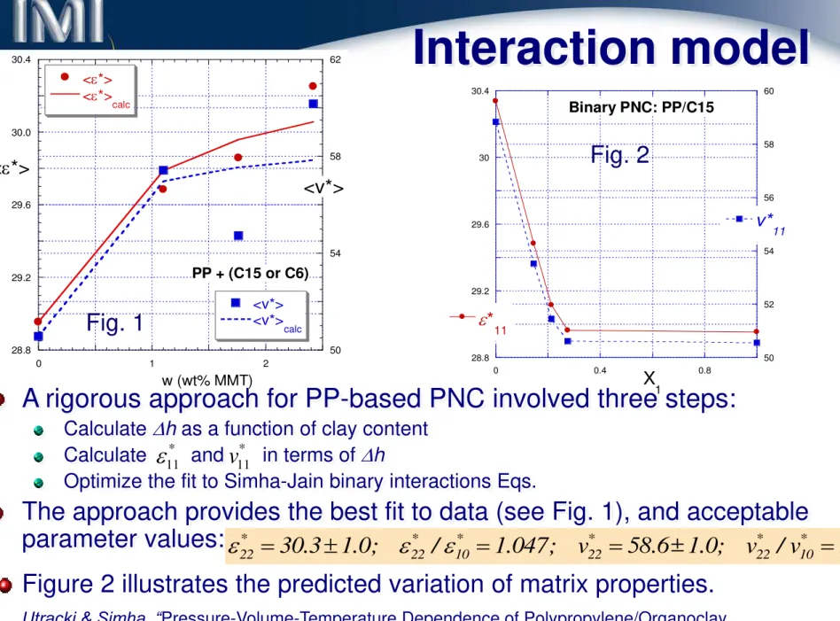
K. Kim, L. A. Utracki and M. R. Kamal, ―Numerical Simulation of Polymer Nanocomposites using
Fundamentals 2
Enthalpy
Solid energy
Entropy
Low area-lattice ratio Poor solubility
Short chain Thin gap
High area-lattice ratio
Unfavorable
F
(+)
Favorable
F
()
Long chain
Thick gap Good solubility
d
s
52
The system: clay
+ compatibilizer, N
g= 100,
+ polymer N
h= 100; at the
grafting density of
g= 0.04
1D computational model
Computed effects of the binary
intercalation parameter on the
chemical composition of the
lattice layers, z = 1
– 20.
Results:
For chg > 0 compatibilizer is
immiscible with h-polymer
For chg = 0 the system is miscible.
The miscibility increases with chg
and Ngr .
Data: K. Kim & LAU, 2003
chg
Compatibilizer content
Fig. 1;
c
hg= 0.02
Fig. 2;
c
hg= 0.00
Fig. 3;
c
hg= -0.02
max 0.02
max 0.07
max 0.05
Optimization of compatibilizer content
The 1D free energy (h ) for homopolymer with N
h= 200
depends on:
Compatibilizer Ng [25, 200],
g [0.02, 1],Binary interaction parameter: chg [0.02, 0.02].
Following Balazs et al. publications, the 1D model assumes
clay platelet enrobed by intercalant.
54
The binary interactions are taken for the PNC with PP as the
matrix, i.e., for PP/compatibilizer/intercalant/clay.
The influence of the solid area-lattice ratio (
e
) and binary
interaction (
c
hg) on the excess free energy
Statistical chain lengths:
Ng = 200, Nh = 400, No = 10
Surface grafting density:
g = 020%,
o = 70%,
v = 25% Solid-solid interactions: A = 20(kBT),e
[0,50] Binary interaction parameters:c
hg = 0,c
ho = 0,c
go = 0,c
hs = 0.01,c
gs =
0.01,c
os =
0.021D-SCF model
2
Comparing with the preceding graph one may conclude that
doubling the void fraction significantly improved miscibility (
F <0).The influence of the solid area-lattice ratio (
e
) and binary
interaction (
c
hg) on the excess free energy
(higher vacancyfraction)
Statistical chain lengths:
Ng = 200, Nh = 400, No = 10
Surface grafting density:
g = 020%,
o = 70%,
v = 510%Solid-solid interactions:
A = 20(kBT),
e
[0,50]Binary interaction parameters:
c
hg = 0.0,c
ho = 0,c
go = 0,c
hs = 0.01,c
gs =
0.01,c
os =
0.0256
Favorable polymer/compatibilizer interactions, along with
favorable solid grafting interactions and high vacancy fraction are expected to lead to easy exfoliation.
Statistical chain lengths:
Ng = 200, Nh = 400, No = 10
Surface grafting density:
g = 020%,
o = 70%,
v = 510%Solid-solid interactions:
A = 20(kBT),
e
[0,50]Binary interaction parameters:
c
hg = -0.02,c
ho = 0,c
go = 0,c
hs = 0.01,c
gs =
0.01,c
os =
0.021D vs. 2D or 3D models
In principle, the lattice model of PNC is 3D
In 1D simulations it is assumed that
properties of any lattice cell on a
X-Y plane are identical, varying only
with platelet separation in Z.
In 2D simulation it is assumed that
properties depends on X and Z.
In 3D simulation variation of properties in all three dimensions
is computed.
The computed differences between 1D, 2D and 3D originate
from the different probability for segment placement
(center-edge) hence the configurational entropy and enthalpy (where
pertinent).
x
z
o
Lattice
Clay
x
y
z
o
Lattice
Clay
58 -0.006 -0.004 -0.002 0 0 10 20 z=2 z=3 z=4 z=6 z=8 z=10 F M x 1D
Results for 1D & 2D
The 2D model assumes finite size of clay platelets in the x-direction, and
invariance in the y-direction; the variation with respect to the lateral dimension, y, is averaged,
The Figure displays variation of the excess free energy with the number of cells in x-direction. The data are computed at different distance from the clay surface z = 2 to 10 for: Ng= 25, Nh= 100, g= 0.04, and chg= 0
The 1D prediction is indicated by a horizontal red line.
The 1D model assumes presence of two parallel platelets immersed in a molten polymeric matrix.
In this model the platelets are infinitely large, thus only in the
vertical z-direction the properties may change.
The 1D data of Kim et al. (2004) reproduced results by Balazs et al. (1998).
2D result for 4-components 1
x z0.0,
0.01,
0.01,
0.02
hg hs gs osc
c
c
c
Influence of the binary interaction parameters on the
concentration profiles for:
A = 20(kBT),
N
h= 400, N
g= 200,
No = 100,60
The influence of the bare-solid
area-lattice ratio (
e
) and grafting
density (
g,
o) on the excess free
energy (h = z ).
Statistical chain length
Ng = 200, Nh = 400, No = 10
Surface properties
g [0, 0.2];
o [0.5, 0.9]; and
v [0.02, 0.05]Influence of solid-solid
interactions
A = 20(kBT),e
[0, 20]Binary interaction parameters
c
hg = 0,c
ho = 0,c
go = 0,c
hs = 0.01,c
gs =
0.01,c
os =
0.02Effect of
intercalant degradation
on the concentration
profiles in 2D lattice with:
Ng = 200, Nh = 400, No = 100,
g = 15%,
o = 80%,
v = 25%, A = 20(kBT),c
hg = 0,c
ho = 0,c
go = 0,c
hs = 0.01,
o= 100 %
o= 0.0 %
x zDegradation effect 1
62
Statistical chain length
Ng = 200, Nh = 400, No = 10
Surface property
g = 020%,
o = 70%,
v = 25%Solid influence
A = 20(kBT),
e
= 10,g
o[0.2,1.0]Binary Interaction parameter
c
hg = 0,c
ho = 0,c
go = 0,c
hs = 0.01,c
gs =
0.01,c
os =
0.02Degradation of intercalant can readily be compensated by incorporation of compatibilizer, capable of forming stable bonds with clay surface.
Grafting density of ca. 6% would compensate for the degradation.
Problem Suggested solution
The absence of specific interaction between host and grafted polymer
(chg = 0)
Higher grafting density, and/or higher MW of compatibilizer and organic modifier
(o, g, No and Ng)
Increased bare surface area
(unfavorable solid-solid interactions)
Higher favorable interactions between clay and compatibilizer or intercalant
(stronger negative values for cgsand cos)
Thermal degradation of organic modifier
(increasing go)
- Better attraction between compatibilizer
and solid surface and bigger g
- Less unfavorable interaction between host polymer and solid
Unfavorable host polymer-solid
interaction (chs > 0)
Decrease v as well as saturate the clay
surface with compatibilizer and organic modifier, both miscible with polymer
Solutions of practical
problems
64
Summary of
Mathematical modeling
To reduce surface energy crystalline solids adsorb molecules.
For optimum dispersion of solid there is MW-dependent grafting
density
– above it the grafted particles aggregates (immiscibility).
The Kim et al. SCF model reproduces previous 1D results.
2D computations predict lower miscibility than 1D.
To achieve exfoliation in 4-component system:
Clay: Intercalated (fo 70-80 %), but with surface partially bare for interacting with a compatibilizer (functionalized polymer)
Stable intercalant – no thermal degradation or extraction by melt
Bare clay surface, caused by inadequate intercalation or degradation can be compensated by compatibilization
Compatibilizer (fg 6 vol%)
Strongly interacting with clay surface
High molecular weight (N P)
With non-positive F of mixing with host polymer
Molecular adsorption 1
The specific surface energy of crystalline
solids is unusually high, e.g., freshly cleaved
in mica has
n
1= 4,500 mN/m, crystalline
CaO
n
1= 1,310 mN/m, but amorphous SiO
2only
n
1= 130 mN/m.
Any interphase induces
changes of properties.
1/ 2 2 g r s 1/ 2 2 t sTheories and experiments point out polymer adsorption from
solution or melt on solid surfaces (e.g., on mica flakes).
As shown in the Figure above, neutron scattering indicate
exponential decline of PS concentration in z-direction.
The thickness of the adsorbed layer depends on the system; e.g.,
the rms thickness , viz. 3.6 vs. 4.8 nm for copolymer and
6.8 vs. 9.0 nm for PS, respectively.
0.2 0.6 1
0 4 8 12
Adsorption of PEG from aq. solution
Mw = 25 M w = 100 M w = 900 V olu me fr a ct ion of ad sor b e d po lym er, f(-)
66
Molecular adsorption 2
Adsorption of polymer on solid
surface was predicted by numerical methods.
Klein experimentally showed that on
mica flake a layer of PS is adsorbed
from toluene solution to a thickness of 110 nm!
Luengo et al., [1997] observed a 3-layer structure of PBD on mica:
z < 6 nm – solid-like
6 < z < 100 – elastomeric z > 100 nm – bulk behavior
Thickness of the adsorbed solid-like layer, zs, depends on Mw: Surface Force Analyzer (SFA) 2
6.46 6.75log
;
0.99996
s wz
M
r
Molecular adsorption 3
PBD (M
w= 6.95 kg/mol) was
studied in a SFA at:
g
< 30%,
n
(Hz) = 0.03 to 80
and gap, 2z = 10 to 250 nm.
As shown in the Figures
(right), three regions of
dynamic behavior were
identified:
1. For 2z > 200 nm the angle between strain and stress
d /2, and - the bulk behavior.
2. At smaller gaps d < /2, and G'
and G'' increased, showing an ―elastomeric-plateau‖, i.e., a 3D structure.
3. At gaps, 2z 12 nm, d = 0, or a
Left Fig. Effect of frequency on the
shear moduli for PBD at T = 25°C, 2z = 10, 30, 180 and 250 nm.
Right Fig. Effect of surface separation
(D = 2z) on the rheological properties of PBD at T = 25°C, n = 13 Hz
68
Clay surface energy
The surface energy,
s=
n
1
A, depends on the
nature and
structure
of material.
Polymer surface tension coefficients at 20°C:
n
1=
10 to 49 mN/mThe surface tension coefficient of crystalline solid:
n
1= 1-8 N/m
The high surface energy causes molecular adsorption
n1 of freshly cleaved mica is 4,500 that exposed to air is 375 mN/m.
Molecular adsorption causes solidification of organic molecules on the clay surface.
The solid layer is ca. 6 nm thick, thus it increases clay platelet thickness from 1 to about 13 nm (see next slide).
Molecular mobility is retarded up to ca. 100 nm from the clay surface.
Another consequence of high surface energy is the aggregation of solid powders.
According to Johnson et al. [1971], the force between two interacting spheres of radius R is:
211
/ 2
11/
V const
N
R
R
Gnomix
®
PVT
instrument
T =
25-400°C, P = 10- 20070
Raw data from Gnomix
®
PVT diagrams for glassy (PS) and semi-crystalline (PP)
polymers (P = 0.1 to 190 MPa)
PVT of PP (RUN 287) Temperature, T( K) 250 300 350 400 450 500 550 S pe ci fic V ol um e -0.10 -0.05 0.00 0.05 0.10 0.15 0.20 0.25 0.30 Col 112 vs Col 114PVT Diagram for PS Nano HS 17
Temperature, T(K) 250 300 350 400 450 500 550 S pe ci fic V ol um e -0.06 -0.04 -0.02 0.00 0.02 0.04 0.06 0.08 0.10 0.12 Col 112 vs Col 114
General notes
PVT measurements offer an easy access to the thermodynamic
properties of a variety of materials.
The direct information is accessed through the temperature and
pressure dependent specific volume changes, e.g.,
and
k
.
Experimentally, S-S eos offers precise description of the PVT
dependence for any liquid tested to date
–
n-paraffins, polymer
melts, blends, composites, foams, nanocomposites.
S-S theory leads to computation of the free volume parameter, h,
as well as the internal energy hence cohesive energy density
(CED) and the solubility parameter,
d
.
The theory has been extended to the glasses, treated as a
pseudo-equilibrium state. However, large effort is still required for the
72
Free volume - definitions
Free volume is that part of space that is left after
subtracting the occupied volume, defined by the atomic
dimensions.
Considering that a molecule or its segment moves in a
cage created by surrounding molecules, its free volume
is defined by the space within which its center can freely
move:
Total specific volume, V
Occupied volume is defined as: V at T = 0 K
→
V
o≡ V(T = 0).
Free volume: V
f= V - V
oFree volume fraction:
f = V
f/ V = 1 - (V
o/V)
Note that f is only a function of V = V(P, T)
S-S Quasi-lattice
Vacancy (hole) fraction: h = 1
– y(V, T)
(excess « free volume ») is a measure of
structural disorder.
Occupied sites Vacant sites
V,T T F F V, T; y(V, T); c / s Minimization : F / y 0 Equation of state : P F / V Free energy
For s-mer:
Scaling parameters: P* = qze
*/sv*; V* = v*/Mo; T* = qze
*/cR → (P*V*/T*)Mo = Rc/sv*: segmental repulsion volume
e
*: segmental attraction energy3c/s: number of external modes (volume-dependent
degrees of freedom) per segment:
Ideal flexible linear chain: 3c/s → 1 Rigid chain: 3c/s → 0
74
S-S Lattice model
2D lattice containing two types
of molecules and holes or
vacancies (open circles). The
binary interaction parameters,
e
ij, are also indicated.
Lattice model is a base for many
theories, e.g., free volume,
cell-hole, tunnel, etc. For example:
In 1941 Huggins & Flory
calculated the configurational
entropy of mixing.
In 1969 Simha and Somcynsky (S-S) published the lattice-hole theory, deriving PVT equation of state, cohesive energy