Publisher’s version / Version de l'éditeur:
Vous avez des questions? Nous pouvons vous aider. Pour communiquer directement avec un auteur, consultez la première page de la revue dans laquelle son article a été publié afin de trouver ses coordonnées. Si vous n’arrivez pas à les repérer, communiquez avec nous à PublicationsArchive-ArchivesPublications@nrc-cnrc.gc.ca.
Questions? Contact the NRC Publications Archive team at
PublicationsArchive-ArchivesPublications@nrc-cnrc.gc.ca. If you wish to email the authors directly, please see the first page of the publication for their contact information.
https://publications-cnrc.canada.ca/fra/droits
L’accès à ce site Web et l’utilisation de son contenu sont assujettis aux conditions présentées dans le site
LISEZ CES CONDITIONS ATTENTIVEMENT AVANT D’UTILISER CE SITE WEB.
Internal Report (National Research Council of Canada. Institute for Research in Construction), 1993-08
READ THESE TERMS AND CONDITIONS CAREFULLY BEFORE USING THIS WEBSITE. https://nrc-publications.canada.ca/eng/copyright
NRC Publications Archive Record / Notice des Archives des publications du CNRC :
https://nrc-publications.canada.ca/eng/view/object/?id=38becfa4-7443-4149-8e24-a6882369affc https://publications-cnrc.canada.ca/fra/voir/objet/?id=38becfa4-7443-4149-8e24-a6882369affc
NRC Publications Archive
Archives des publications du CNRC
For the publisher’s version, please access the DOI link below./ Pour consulter la version de l’éditeur, utilisez le lien DOI ci-dessous.
https://doi.org/10.4224/20358448
Access and use of this website and the material on it are subject to the Terms and Conditions set forth at Column Fire Resistance Test Facility at the Tianjin Fire Research Institute
National Research Consell national
l+I
Council Canada de recherches Canada Institute for lnstitut deResearch in recherche en Construction construction
A . L ,,D
Column Fire Resistance Test Facilitv a t
-
the Tianjin Fire Research Institute
ANALYZED
by Q.F. Han,T.T. Lie and H.J. Wu
Internal Report No. 648
Date of issue: August 1993
This is an internal report of the lnstitute for Research in Construction. Although not intended for general distribution, it may be cited as a reference in other publications.
COLURIN FIRE RESISTANCE TEST FACILITY AT THE TIANJlN FIRE RESEARCH INSTITUTE
ABSTRACT
A test facility to determine the fire resistance of columns was built at the Tianjin Fire Research Institute. This facility was constructed mainly for the purpose of providing testing for the fire resistance of building columns found in China The test results indicate that this facility is reliable and produces comparable results with those at the facility at the National Fire Laboratory of the Institute for Research in Construction, National Research Council of Canada.
COLUMN FIRE RESISTANCE TEST FACILITY AT THE TIANJIN FIRE
I RESEARCH INSTITUTE
1 INTRODUCTION
As a part of a joint research project on the "Fie Resistance Evaluation for Housing (China)" between the Tianjin F i e Research Institute (TFRI) of the Fire Bureau of the Public Security Ministry of China, and the Institute for Research in Construction (IRC), National Research Council of Canada, a testing facility to determine the fue resistance of columns (which will be called the "column furnace" for short) was constructed at TFRI. The column furnace was designed and installed jointly by TFRI and the National Fire Laboratory (NFL) of IRC.
The main purpose for the construction of the column furnace at TFRI was to provide a testing facility for the fire resistance of building columns, commonly used in China In the joint project, experimental studies on the f i e resistance of three reinforced concrete columns were carried out at TFRI.
A photograph of the column furnace at TFRI is shown in Figure 1. Details of the column furnace are described below.
2 Main Characteristics of Column Furnace
at
TFRIThe column furnace at TFRI consists of a loadbearing framework, furnace chamber, combustion system, hydraulic loading system, instrumentation system, and data acquisition and processing system. The main characteristics of this column furnace are given in Table 1.
The column furnace was designed to meet the ISO-834 standard and the China
National Standard GB-9978. In addition, the test furnace can also produce some non standard conditions to which a column may be exposed during the course of a fue with regard to temperatures, structural loads and heat transfer.
2.1 Loadbearing Framework
The loadbearing framework comprises a bottom beam, a upper beam and four steel columns. The bottom beam is futed to the base of the furnace; the upper beam
is
supported by the four steel columns which are connected to the bottom beam. The dimensions of the loadbearing framework are 5.90m in width, 4.73m in depth and 9.80 m
I in height.
Since the outer dimensions of the loadbearing framework, which is designed to meet the required conditions of stiffness and strength, are relatively,
small
the loadbearing framework was easily manufactured and installed. Because the loads applied to a test column in the furnace are carried by the loadbearing framework, only the weight of the furnace is carried by the base. Therefore, a solid and deep base was not needed.2.2 Furnace Chamber
The furnace chamber, whose floor area is 2.6 x 2.6 m, is made of an insulating material that will give a high heat transfer to the specimen. Since this insulating material has a low heat conductivity, the temperature rise on the outside of furnace chamber was found to be only 8 "C after a 6 hour test.
The roof of the furnace chamber can be moved upwards or downwards in a range that will provide furnace chamber heights varying from 3.0 m to 4.2 m and enables testing of columns of different lengths. The roof functions as a blow-out panel as a safety measure against explosions.
2.3 Combustion System
There are 16 diesel oil burners in the furnace chamber arranged in four columns containing four burners each. The total capacity of the burners is approximately 4187 kW, which should be sufficient to simulate any fxe severity encountered in practice. In order to simulate different temperature conditions, the oil supply to the burners can be controlled by a programmable controller. In addition, each burner can also be adjusted individually, which provides a high degree of temperature uniformity in the furnace chamber. The accuracy in controlling the furnace temperature is i 10 "C.
The pressure in the furnace chamber is also adjustable and is set somewhat lower than atmospheric pressure.
2.4 Hydraulic Loading System
The hydraulic loading system consists of one axial loading jack, two eccentric loading jacks and two lateral loading jacks. The axial loading jack was designed for a maximum load of 5000 kN. This capacity is sufficient to subject most of columns, used in China, to their design loads. The capacity of the two eccentric loading jacks
is
300 kN at an eccentricity of 500 mm. The other two jacks exert lateral loads at the top of the column, to simulate the loads and displacements due to floor expansion during a fire. The capacity of the lateral loading jacks along the x-axis is 400 kN; the capacity along the y- axis is 150kN.
The loads are measured by pressure transducers that send electric signals to a load controlling system, controlled by hydraulic servo valves.
2.5
Instrumentation SystemThe furnace temperatures are measured with the aid of eight Chrornel-Alurnel thermocouples installed 0.1 m from the test specimen at various heights. There are two thermocouples placed opposite each other every 1
rn
along the height of the furnace chamber, starting from the floor. The eight temperatures, measured by these thermocouples, are averaged automatically and the average temperature is used as the criterion for controlling the furnace temperature.The axial deformation of test columns is measured with a SONY digital linear potentiometer. The accuracy of this measurement is
*
0.001 mm.2.6
Data Acquisition a n d Processing SystemThe data acquisition and processing system is a
FLUKE
Helios-I data acquisition system and a microcomputer. The Helios-I data acquisition system can acquire analog and digital data (i.e., temperature, voltage, current, strain, displacement, pressure). The Helios-I data system uses LABTECH NOTEBOOK software with the microcomputer. During a test, the test data can be stored, displayed, printed and saved by the system. After a test, LOTUS 1-2-3 software is used to process the test data saved on a hard disk.3
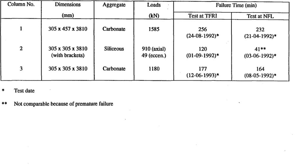
ConclusionSince the column furnace was built, three fire resistance tests on reinforced concrete columns, identical to three columns tested at the NET., have be carried out. These results are given in Table 2.
The test results indicate that the newly built column furnace at TFRI is reliable, and comparable with the column furnace at the Nn. The TFRI furnace can carry out fwe resistance tests on columns, used in China, according to the I S 0 Standard, the China National Standard or other testing standards, including North American Standards.
4 Acknowledgments
The column furnace was built in a joint effort by staff from of the Nn and TFRI. These staff members are: Mr. John MacLaurin, Mr. John C. Latour, Mr. G.H. Wang, Mr.
J.Y. Hu, Mr. Z.H. Dong, Mr. W.B. Qiu, Mr. Y.C. Feng, Ms. S.Y. Bai, Mr. W.H. Song, Ms X.H. Liu and Mr. Y.J. Zhou.
Partial funding for this project was obtained from the International Development Research Centre.
Table 1. Main Characteristics of Column Furnace at TFRI
Characte'ristics
Floor area of furnace chamber Inner height of furnace chamber Fire exposure height of specimens Size of loading frame
Maximum pressure of hydraulic loading system Accuracy of controlling and measuring loads Accuracy of measuring displacements
Capacity axial load
Maximum movement of axial jack Maximum speed of axial jack Capacity of eccentric load
Maximum movement of eccentric jack Capacity of lateral load along x-axis Capacity of lateral load along y-axis Fuel
Number of burners Capacity of 16 burners
Oil consumption of 16 burners Ignition of burners
Pressure of fuel oil supply system Pressure of air supply system
Type of thermocouples for temperature measurement
Details
2.6 mx
2.6 m up to 4.2 m from 3.0 m to 4.2 m 5.9 mx
4.73 mx
9.8 m 3.2 MPa * 2 % k 0.001 mm 5000 kN 400 mm 22 mmtmin 300 kN (eccentricity 500 mm) 450 mm 400 kN (to be installed) 150 kN (to be installed) diesel oil 16 approximately 4187kW
191 to 214 kglhourPilot flame lights oil burners. 49 to 294 kPa
6.9 kPa Type [Kl
Table 2. Comparison of Results of columns tested at TFRI and NFL
-
-*
Test date**
Not comparable because of premature failure Column No. 1 2 3 Dimensions (mm) 3 0 5 x 4 5 7 ~ 3 8 1 0 305 x 305 x 3810 (with brackets) 305 x 305 x 3810 Ag@egate Carbonate Siliceous Carbonate Loads OrN) 1585 910 (axial) 49 (eccen.) 1180Failure Time (min) Test at TFN 256 (24-08-1992)* 120 (01-09-1992)* 177 (12-06-1993)* Test at