HAL Id: hal-02999720
https://hal.archives-ouvertes.fr/hal-02999720
Submitted on 2 Dec 2020HAL is a multi-disciplinary open access archive for the deposit and dissemination of sci-entific research documents, whether they are pub-lished or not. The documents may come from teaching and research institutions in France or abroad, or from public or private research centers.
L’archive ouverte pluridisciplinaire HAL, est destinée au dépôt et à la diffusion de documents scientifiques de niveau recherche, publiés ou non, émanant des établissements d’enseignement et de recherche français ou étrangers, des laboratoires publics ou privés.
Full-Silicon 98.7% Efficient Three-Phase Five-Level
3-port UPS Architecture with Wide Voltage Range
Battery based on Multiplexed Topology
Kepa Odriozola, Thierry Meynard, Alain Lacarnoy
To cite this version:
Kepa Odriozola, Thierry Meynard, Alain Lacarnoy. Full-Silicon 98.7% Efficient Three-Phase Five-Level 3-port UPS Architecture with Wide Voltage Range Battery based on Multiplexed Topology. 22nd European Conference on Power Electronics and Applications (EPE’20 ECCE Europe), Sep 2020, Lyon (virtuel), France. pp.1-13, �10.23919/EPE20ECCEEurope43536.2020.9215927�. �hal-02999720�
Full-Silicon 98.7% Efficient Three-Phase Five-Level 3-port UPS Architecture
with Wide Voltage Range Battery based on Multiplexed Topology
Kepa Odriozola
1 ID, Thierry A. Meynard
2, Alain Lacarnoy
31 Energy Management, Schneider Electric IT France, Grenoble, France
2 LAPLACE Laboratory, CNRS-INPT-UPS
,Toulouse, France
3 Industrial Automation
3,Schneider Electric Indus. SAS
,Grenoble, France
Keywords
Multilevel converters, Emerging topology, Efficiency, Uninterruptible Power Supply , Energy Storage, Batteries, Modulation strategy.
Abstract
This paper proposes a new three-phase Multilevel 3-port converter topology based on Multiplexed topology concept which is especially intended for high-power Uninterruptible Power Supplies (UPS) applications with wide battery voltage range and well adapted for high step-down voltage conversion ratio. Compared to other high-voltage conversion ratio Multi-Cell converters, the Multiplexed concept allows cascading power conversion stages without any intermediate filter and optimizing power density. In the studied case it will be used to transfer power between a 1200V DC source and 400V/480V AC load and grid. The proposed converter topology achieves very high efficiency, up to 98,7% in direct AC-to-AC power conversion mode using reduced number of silicon low blocking voltage semiconductor devices. The Hardware In the Loop (HIL) assessment has enabled the development of the modulation strategy and validated the performance of the converter. To validate the feasibility of the Multiplexed concept, both at the topological level and the modulation strategy, of the 5-Level Multiplexed 3-port topology for UPS applications a 100-kW hardware demonstrator featuring a volumetric power density of 3.68 kW/dm3 (60.3 W/in3) has been built.
Introduction
The growing penetration of renewable energies at worldwide scale is playing a leading role in the evolution of power electronics systems. Therefore, new high efficient power-electronic systems and associated control strategies are needed to make this transition possible. From the introduction of the first well known multi-level topologies [1, 2, 3] to their industrial maturity, many applications have taken advantage of their improved performances [4].
Regarding the already consolidated 1500V technology, several studies [5, 6, 7, 8] have shown in the past decade the economic benefits in the PV sector. Many manufacturers have already developed and installed photovoltaic inverters throughout the world and several devices (converters, contactors, combiner boxes, etc.) are already approved by global safety certification companies [9, 10]. Along with this, it should be noted that the grid integration of distributed energy sources such as Photovoltaic (PV) systems accompanied by Battery Energy Storage Systems (BESS), both at utility-scale and Behind-the-Meter (BTM) or residential-industrial level [11] is becoming more important. Proof of this are the products that are already available on the market [12, 13, 14]. This trend, today well established for
system-oriented UPSs is now observed for the next generation Giant Data Centers. The installed power capacity in Data-Centers
Fig. 1: General schematic of the proposed 3-port DC-AC-AC Multiplexed Power Converter. DC port side is connected to the battery pack system of the UPS. Each AC port is connected either to the grid and the load respectively.
is increasing exponentially with the never ending expansion of the global data sphere [15] and therefore battery-based UPS systems are becoming a key factor for today’s Original Equipment Manufacturers (OEMs) and technology firms in this area.
Among the wide variety of industrial applications, UPS systems [16, 17] as well as other applications such as Medium-Voltage (MV) drives, energy storage systems (ESS), grid-tied systems for distributed generation sources such as PV, wind turbines and microturbines and HVDC (High-Voltage DC) transmission systems [19, 18, 20, 21, 22, 23, 24, 25] which make use of back-to-back configuration. Typical back to back configuration systems use mainly both identical topologies for inverter and AFE (Active Front End) converter for decoupling the grid from the loads. Therefore, the total cost of this type of conversion systems is double that of a single inverter stage. Therefore, obtaining high efficiency and high power density in this type of conversion architecture, whatever the application, with current semiconductor and magnetics technologies at low cost is still a big challenge.
This paper proposes a new three-phase multilevel 3-port converter topology based on multiplexed topology concept [26] and which is especially intended for high-power UPS applications with wide battery voltage range, which achieves very high efficiency, up to 98,7% in direct AC-to-AC power conversion mode using reduced number of silicon low blocking voltage semiconductor devices.
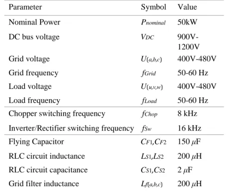
Table I: Specifications of the 5-Level three-phase 3-port DC-AC-AC Multiplexed Power Converter.
Parameter Symbol Value
Nominal Power Pnominal 50kW
DC bus voltage VDC
900V-1200V
Grid voltage U(a,b,c) 400V-480V
Grid frequency fGrid 50-60 Hz
Load voltage U(u,v,w) 400V-480V
Load frequency fLoad 50-60 Hz
Chopper switching frequency fChop 8 kHz Inverter/Rectifier switching frequency fSw 16 kHz
Flying Capacitor CF1,CF2 150 μF
RLC circuit inductance LS1,LS2 200 μH RLC circuit capacitance CS1,CS2 2 μF Grid filter inductance Lf(a,b,c) 200 μH
3 3 Battery System DC DC+ A,B,C U,V,W DC -AC AC Load Grid + -
Grid filter capacitance Cf(a,b,c) 50 μF Load filter inductance Lf(u,v,w) 200 μH Load filter capacitance Cf(u,v,w) 50 μF
The structure and conversion stage topologies of this Multi- Level Multiplexed topology will be described in Section II - 3-Port DC-AC-AC Multiplexed Converter. The modulation strategy for the proposed
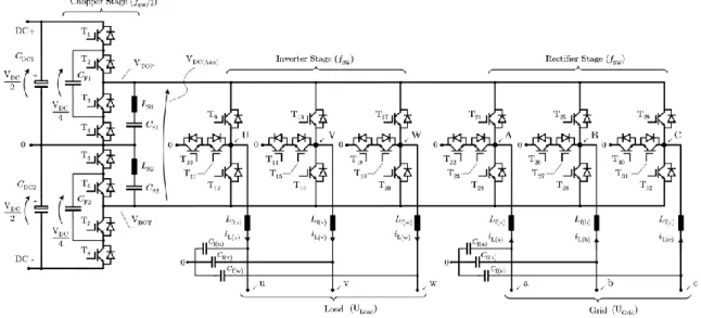
Fig. 2: Detailed schematic of the 5-Level three-phase 3-port DC-AC-AC Multiplexed Power Converter. The chopper stage consists of two 3L-Flying Capacitor converters. Both inverter and rectifier stage consists of three-phase 3L-T type NPC converters.
topology is the described in Section III - Modulation Strategy, starting with the basic principle and then describing more in-depth the chopper and inverter modulation. Then, control strategy is described in Section IV - Control Strategy. Simulation results are presented in Section V - Simulation Results. Hardware implementation is introduced in Section VI - Experimental Results. Finally, the conclusions are given in Section VII - Conclusions.
3-Port DC-AC-AC Multiplexed Converter
The proposed power conversion architecture (see Fig. 1) is based on multiplexed converter topology presented in [26, 27]. As explained above, the most typical configuration in UPS systems is back-toback. Therefore, the most conventional would be to serialize two 5-Level Multiplexed DC-AC Converter stages that share the same DC-link.
However, the concept of control associated with multiplexed converters allows in this case, to mutualize the chopper stages. Thus, the inverter output stage and the rectifier input stage share the same chopper stage. In this way, it is possible to reduce the number of switches drastically and obtain better efficiency with respect to the back-to-back configuration.
The proposed power conversion topology is shown in Fig. 2. In principle, the DC-DC chopper and DCAC inverter can be any converter with two or more voltage levels, under the condition of adapting the modulation scheme according to the selected topological variant. In the studied case, for a maximum voltage of 1200V at the DC-link, different combinations of multi-level topology can be derived. Going from 3 to n levels, where n is the number of voltage levels at the output of each converter. Fig. 2 shows the power circuit of the three-phase 5-Level 3-port DC-AC-AC Multiplexed Power Converter with
3level Flying Capacitor chopper and 3L-T-NPC inverter and rectifier configuration. In this paper only this configuration will be analyzed.
Semiconductor Selection
One of the main features being efficiency and low cost, the selection of semiconductors becomes essential. Only silicon components are used in order to reduce the total cost but of course wide band gap components could be used to reduce losses and improve efficiency and power density.
The first originality of this topology is that the choppers deliver square voltage waveforms with steps of one fourth of the DC-bus; assuming that an appropriate control pattern is used, the voltage applied to the inverter switches may thus be limited to 3/4 or even 1/2 the DC-bus voltage in order to ensure high immunity to cosmic rays [28] and obtain a high reliability, which of course helps maintaining a high efficiency. In our case, the inverter and rectifier stages are realized with 1200V, 75A High Speed IGBTs IKY75N120CS6 from Infineon. The typical voltage across the semiconductors of the flying capacitor chopper is 1/4 of the DC-bus voltage, and 650V, 75A Low-VCEsat IGBTs IKZ75N65ES5 from Infineon have been selected here. In order to handle the high current of the load and to reduce the conduction losses, each switch consists of four TO-247 package devices in parallel.
Voltage Balance on Flying Capacitors
In order to limit the overvoltage on the inverter and rectifier we must guarantee a correct balancing of the flying capacitors. In the offline power conversion mode and in the battery recharge mode, the power flow circulates through the choppers flying capacitors. In this way, under normal circumstances, it is possible to obtain a natural balance of the capacitors [29]. However, in the AC-AC direct energy conversion mode, the power flow circulates from the grid directly to the load via the variable DC-bus. Therefore, the current circulating through the flying capacitors is negligible even though the choppers continue to operate to generate in the variable DC-bus (VDC(Aux)) the maximum and minimum part of
the voltage of the two three-phase systems (grid and load). Due to imperfections of the control there will also be small unwanted current components; the inherent self-balancing property of these converters might be lost which is not acceptable because unbalanced voltages could destroy the semiconductors. To guarantee balancing of the flying capacitors there are various techniques and we can distinguish active and passive methods. In order to avoid introducing additional distortions on the differential voltage pattern of the choppers by means of the duty cycle correction [30] the passive methods will be preferred here. Among the passive methods there are different circuits described in the literature like [31, 32]. However, these linear circuits as well as the non-linear variants are designed considering several assumptions, one of these being a constant supply voltage of the converter. A balance-booster design [33], be it internal or external, that follows the input voltage variations becomes complicated, mainly due to its limitations from the implementation point of view.
For this reason, it has been decided to use an RLC circuit [34]. This shunt passive filter essentially acts as a notch filter connected in parallel to the output of each chopper offering a very low impedance at the switching frequency of these choppers. When the voltage of the flying capacitor is unbalanced, each chopper generates at the output, voltage harmonics at the switching frequency. Since the RLC filter is tuned to the switching frequency (i.e. 8kHz) it presents very low impedance, ZLC (2·π· fChop), forcing the
circulation of harmonics of current at the same frequency that favor the rebalancing of the capacitors. The inductance and capacitance values used in simulation for the RLC circuit are given in Table I and the design values in Table II.
Modulation Strategy
Unlike conventional three-phase topologies, the multiplexed topology does not have independent phase legs. Therefore, each conversion stage module must be controlled separately. As a basic principle of modulation, sinusoidal PWM modulation can be used to make it simple.
Similar to the modulation strategy described in [26] the main concept is to generate respectively the highest and the lowest part of the 6 voltages (3 of the grid and 3 of the load) by respectively Top and Bot choppers. Doing so, 2 of the 6 inverter legs can be saturated and stop switching. The 4 other inverter/rectifier legs need to switch to generate the appropriate grid side and load side three-phase voltage systems.
Chopper Modulation
Regarding the control of DC-DC choppers, the main objective is to generate the highest and lowest side of the both grid side and load side three-phase voltage systems. The chopper section involving capacitors has a strong requirement to ensure that the average current is zero and that the voltage of this capacitor can be regulated. Another objective will be to minimize the static voltage seen by the inverter stage in order to respect the voltage rating of the inverter switches. As a first approach, self-balancing
t [ms]
Fig. 3: Main simulation waveforms of the 5-Level three-phase 3-port DC-AC-AC Multiplexed Power Converter (see Fig. 2) operating with a DC-link (Battery) voltage of 1200V during direct AC-AC power conversion mode (cf., Fig. 4a) and a load output power of 50kW. (a): Grid reference voltages; (b): Load reference voltages; (c): Chopper output voltages, VTOP in green, average value of VTOP in blue, VBOT in
red, average value of VBOT in yellow; (d): Multi-level voltage of the node A at the input of the Rectifier
stage referenced to the DC-link midpoint (cf. Fig. 2); (e): Grid phase currents; (f): Multi-level voltage of the node U at the output of the Inverter stage; (g): Inverter filter inductor voltage of phase U; (h): Load phase currents; (i): Flying Capacitor voltages. Please note that the grid and load voltages are phase-shifted by 60◦ making the choppers generate the maximum of the 6-voltage system.
mechanism can be tried by applying a carrier based PWM modulation scheme such as Phase Shifted (PS) [35]. Another possibility is to use Phase Disposition (PD) by means of state machines like in [36] and [37], but in this kind of schemes extra commutations are needed and the balancing of flying capacitor could become complex. We therefore use PS sawtooth carriers at 8kHz switching frequency are used for having the absolute control of turn-on and turn off moments or rising-up and falling-down instants of the voltage created by each chopper.
Rising sawtooth carriers for the Top chopper and falling sawtooth carriers for the BOT chopper have been selected. In order to minimize the static voltage, VDC,Aux (cf., Fig. 2) seen by the inverter and rectifier
stages over the majority operating points, there will be a relative phase shift of some switching periods between the Top and Bot choppers carrier signals. In this way when high modulation index is required, consecutive steps of voltage levels on the differential voltage of the chopper outputs can be avoided. The feature of the Flying Capacitor converter to double the apparent frequency at the output leads to a chopper switching frequency equal to half that of the inverter. Consequently, the switching losses are reduced too. This switching frequency ratio between chopper and inverter must be respected if the calculation of the inverter and rectifier duty cycle (introduced in the next section) is to be accurate.
Inverter Modulation
The voltage generated at the output of the inverter and rectifier must be synthetized by means of the voltage already switched by choppers. Hence, the duty cycle for inverter and rectifier is defined in function of choppers duty cycles and inverter and rectifier voltage reference. For that, duty cycles of each output inverter and rectifier arm are determined separately by means of two-dimensional look-up-tables using a pre-calculated PWM method. Contrary to the disadvantages of this type of techniques [38, 39], in this case, the computational cost of the algorithm is not high and duty cycles can be calculated with a high accuracy. The calculation of duty cycles is made off-line throughout two piecewise interpolations and explained more in depth in [26].
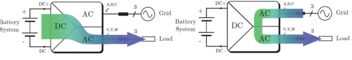
(a) DC-AC power conversion mode. (b) AC-AC power conversion mode.
Fig. 4: Power transfer flow in the proposed three-phase 3-port Multiplexed Converter for different modes of power conversion.
The applied modulation scheme has the intrinsic property of freezing the inverter phase legs when necessary. Once the duty cycle is computed, a dedicated scheme of modulation must be applied for the inverter and rectifier output stages. Gate signals must be generated in function of selected topology. For
our configuration, three-phase three-level T-type NPC has been chosen. For being compatible with the chopper modulation and mainly with the inverter duty cycle offline calculation we must choose carriers at 16kHz switching frequency such that they are in counterposition to the chopper carriers. In this case, the upper switch cell of the inverter must depend on the carriers of the Top chopper and vice versa. Therefore, having selected rising sawtooth carriers for the Top chopper then the carrier modulating the upper cell of the inverter must be of type falling sawtooth carrier. In this way, we ensure that the interpolation equations with which the duty cycle table is constructed to control the inverter stage are fair. Moreover, each switch cell will guarantee ZVS (Zero Voltage Switching) operation for inverter and rectifier arms (at least one turn-on or turn-off per switching period in function of the selected rising or falling front carrier configuration) thanks to the extra slight phase shift introduced between Top and Bot choppers and inverter stage carriers. Consequently, the desired switching pattern is obtained for the inverter and rectifier, thus only two phase legs are swiching at a time when both three-phase voltage systems have same amplitude, one on the grid-side, the other on the load-side.
Control Strategy
New regulations (i.e. IEC, IEEE 1547, etc.) impose more functionalities on electrical energy conversion devices in order to interact with the different types of current networks. These devices must be able, for example, to provide a certain amount of reactive power during a certain period of time in order to cope with eventual accidents or instabilities that may occur.
In practice, to fulfill the requirements imposed on today’s new UPS equipment, different types of control laws can be applied to the proposed topology. Depending on the mode of operation, the management of the direction of the active (PLoad, PGrid) or reactive power (QLoad, QGrid) flow will be different. Thus, we
can distinguish mainly the inverter mode of operation, the battery charging mode in rectifier operation (cf., Fig. 4a), the grid following or grid forming mode of operation, and the AC-to-AC direct energy conversion mode (cf., Fig. 4b) which is enabled thanks to the mutualization of the chopper stage.
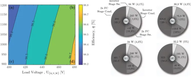
Fig. 5: Efficiency map of the 5-L three-phase 3-port DC-AC-AC Multiplexed Power Converter in single DC-AC power conversion mode (cf., Fig. 4a) feeding a 50 kW resistive load for different line-to-line load voltage and DC-bus voltage values
Fig. 6: Loss breakdown for 4 (corner: a,b,c,d) operating points at Fig. 5 of the 5-L three-phase 3-port DC-AC-AC Multiplexed Power Converter in single DC-AC power conversion mode at 50kW. In the AC-to-AC direct power conversion mode, unlike conventional back-to-back configurations in which all energy passes through the DC-link, the proposed topology partially bypasses the DC-link: power may be transferred from grid to load via only the inverter and rectifier.
It is necessary to emphasize that for all the above-mentioned operating modes, it is necessary to apply a preload strategy of DC-bus capacitors voltage as well as chopper flying capacitors, in order to guarantee a balanced distribution of the total DC link voltage [40, 41]. At any moment of the preload, it is necessary
to ensure that the flying capacitor is charged to its nominal voltage. This is achieved by combining a classic preload method via a resistance that is later bypassed and a DC-bus voltage control loop that takes care of charging the DC link to the battery voltage in boost power conversion. The RLC filters connected in parallel to the output of each chopper will ensure that in case of unbalance the distribution of the voltage is compensated.
Simulation Results
The performance of the three-phase 5-Level DC-AC-AC Multiplexed Converter has been simulated in the PLECSR software using specifications described in Table I. All operating modes have been tested in
simulation as well as the thermal performance of the converter using semiconductors described in Subsection - Semiconductor Selection.
(a) VDC = 900V (b) VDC = 1200V
400 420 440 460 480 400 420 440 460 480
Load Voltage , U(u,v,w) [V] Load Voltage , U(u,v,w) [V]
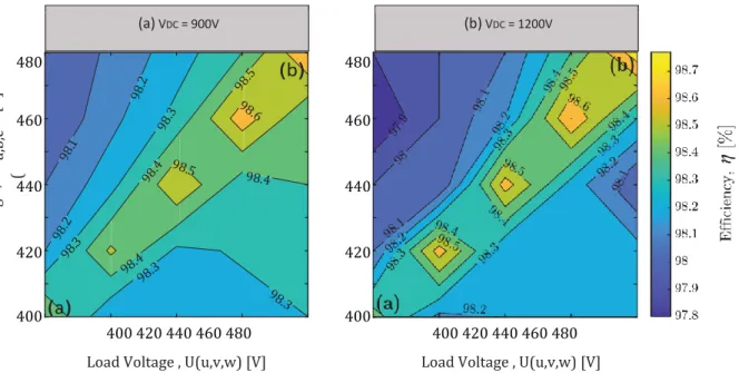
Fig. 7: Efficiency map of the 5-L three-phase 3-port DC-AC-AC Multiplexed Power Converter in direct AC-AC power conversion mode (cf., Fig. 4b) feeding a 50 kW resistive load for different line-to-line grid and load voltage values and identical phases and for VDC= 900V and VDC=1200V.
(a) VDC = 900V (b) VDC = 1200V
Fig. 8: Loss breakdown for 2 (corner: a,b) operating points per each value of DC-bus (battery) voltage at Fig. 7 of the 5-L three-phase 3-port DC-AC-AC Multiplexed Power Converter in single DC-AC power conversion mode at 50kW.
Fig. 3 shows the multilevel performance of the three-phase 5-Level Multiplexed Converter (illustrated in Fig. 2) over two periods of fundamental output frequency. Regarding the simulation conditions for
400 420 440 460 480 400 420 440 460 480
the illustrated scenario, the DC-bus (battery voltage) is 1200V, the inverter works in open loop with a reference voltage between phases equal to 400V/50Hz while the rectifier works in PFC mode with closed loop control of the grid currents. In this mode, power is transmitted directly (AC-AC power conversion mode, Fig. 4b) from the mains to the load without passing through the DC-bus, i.e. the battery, thus reducing overall losses and increasing efficiency. The grid voltage is 440V/50Hz with a relative phase shift of 60 with respect to the load voltage. It can be observed that at all times the choppers are responsible for synthesizing the maximum and minimum of the two three-phase systems (grid and load). It can also be seen that the voltage ripple of the flying capacitors is kept below 5% of the nominal voltage thanks to the RLC filters.
Fig. 5 shows the efficiency map of the converter in single DC-AC power conversion mode (cf., Fig. 4a) for different values of load DC-bus (battery) voltage. The same efficiency is expected for the converter in grid-forming mode when rectifier stage is working as inverter. Loss distribution per each conversion stage (2x 3-Level Flying Capacitor Chopper Stage and Inverter Stage) of the theoretical design is shown in Fig. 6.
Fig. 7 shows the efficiency map of the converter operating the system in AC-AC power conversion mode (cf., Fig. 4b) for different values of load and mains voltage and two constant values of battery voltage. Loss distribution per each conversion stage (2x 3-Level Flying Capacitor Chopper Stage, Inverter Stage and Rectifier Stage) of the theoretical design is shown in Fig. 8. We can observe this time how the losses within the Flying Capacitor choppers have been drastically reduced with respect to the inverter mode of operation. Most of the losses, around 90%, are located in the inverter and rectifier stages.
Experimental Results
To validate the proposed control strategy and the suitability of the 5-Level Multiplexed 3-port topology for UPS applications, the HIL test system and hardware implementation of the three-phase 5-Level 3-port Multiplexed topology will be presented in the following.
Hardware-In-the-Loop (HIL)
The digital implementation of the proposed modulation and control strategy and all operating modes, including start-up precharge strategy of flying capacitors and DC-bus, has been validated via HIL. The control is implemented by coding two Real-Time Imperix B-Box RCP 3.0 that interfaces with the TyphoonHIL 602+ system. Fig. 9 shows the HIL waveforms of the proposed converter during inverter operating mode.
Fig. 9: Hardware In the Loop (HIL) waveforms of the five-level output voltage of the phase U of the 5-Level three-phase 3-port DC-AC-AC Multiplexed Power Converter shown in Fig. 2 (300 V/div, referenced to the DC-link midpoint, 5 ms/div) and the three-phase (u,v,w) load currents (120 A/div) during inverter operating mode at 50 kW. The HIL real-time waveforms are in accordance with the simulation results shown in Fig. 3.
iL(V) iL(W) iL(U)
Hardware Implementation
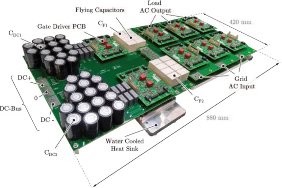
To validate the feasibility of the multiplexed concept of the 5-Level Multiplexed 3-port topology for UPS applications, a 100-kW hardware demonstrator shown in Fig. 10 has been built using components described in the Table II.
Experimental Waveforms
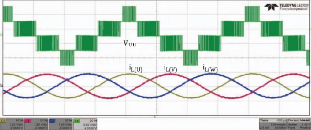
The main measured waveforms taken with a resistive load and operating the system in inverter mode are presented in Fig. 11 for 15.7 kW operation. The five output voltage levels are shown for phase U together with the Top chopper output voltage (VTOP), as well as the load phase voltage and currents. We can
deduce from the shape of the 5-Level voltage of the phase U (VU0) that the voltage of the flying capacitors
is kept balanced thanks to the RLC filters.
Conclusions
In this paper, a 98.7% 3,68kW/dm3 three-phase 3-port multilevel converter topology based on
Multiplexed structure was proposed. This topology has the ability to achieve a high step-down voltage
con-Fig. 10: Hardware prototype of the 100kW three-phase 5-Level DC-AC-AC Multiplexed Converter, measuring 420mm 880mm 110mm (16.53 in 34.64 in 4.33 in). The final volumetric power density (without considering RLC Shunt filters, output and input LC filters of each AC port and auxiliary power) is 3.68 kW/dm3 (60.3 W/in3).
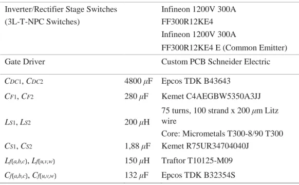
Table II: Main components of the hardware prototype.
Component Value Part Number
Chopper Stage Switches Mitsubishi 1200 400A
Inverter/Rectifier Stage Switches (3L-T-NPC Switches)
Infineon 1200V 300A FF300R12KE4 Infineon 1200V 300A
FF300R12KE4 E (Common Emitter)
Gate Driver Custom PCB Schneider Electric
CDC1, CDC2 4800 μF Epcos TDK B43643
CF1, CF2 280 μF Kemet C4AEGBW5350A3JJ
LS1, LS2 200 μH
75 turns, 100 strand x 200 μm Litz wire
Core: Micrometals T300-8/90 T300
CS1, CS2 1,88 μF Kemet R75UR34704040J
Lf(a,b,c), Lf(u,v,w) 150 μH Traftor T10125-M09
Cf(a,b,c), Cf(u,v,w) 132 μF Epcos TDK B32354S
version ratio which makes it suitable for new low-medium voltage applications with wide range of input voltage such as UPS systems.
Cascading inverter and choppers without intermediate filtering elements leads to a reduction of the voltage applied to the switches of the inverter and rectifier stages (in some cases ZVS operation is possible), thus reducing the switching losses and indirectly the conduction losses (since switches with a lower
Fig. 11: Experimental waveforms of the five-level 5-Level three-phase 3-port DC-AC-AC Multiplexed Power Converter shown in Fig. 2 operating the system in inverter mode for 15.7 kW operation (VDC=600V, Vu=150V, iL(U)=35A). (a): V(u,v,w) (100 V/div), Load phase voltages; (b): VTOP (100 V/div),
output voltage of the Top 3-Level Flying Capacitor Chopper; (c): iL(U,V,W) (20 A/div), output filter
inductance currents; (d): VU0 (100 V/div), five level output voltage of the phase U referenced to the
DC-link midpoint. iL(U,V,W) (20A/div) V(u,v,w)(100V/div)
V
TOP (100V/div) V U0(100V/div) ) a ( (b) (c) (d)voltage rating can be used). The switching losses in the inverter are also reduced because the Max and Min voltage waveforms of both grid and load three-phase systems are synthesized by the choppers, so at any time two of the inverter legs are not switching. These features enables switching at relatively high frequency and helps in the end to obtain a high power density. Moreover, compared to conventional single three-phase multilevel topologies it reduces the number of modules needed because of the mutualization of the chopper stage. It should also be noted that it only uses only silicon low blocking voltage semiconductors devices reducing the overall cost of converter.
Furthermore, a higher efficiency can be obtained in AC-to-AC power conversion mode by allowing the main power transfer via the inverter stages only, with a very small portion of currents flowing via the chopper stages. In this paper an appropriate control strategy for the novel topology is presented. Simulations have been conducted on the PLECS software environment with good results especially in terms of efficiency. Real time feasibility of the control strategy has been checked using two Imperix B-Box RCP 3.0 and Typhoon HIL 602+ devices and a scale 1 prototype has been built and is now ready for testing. The first experimental results (up to 55 kW) have globally demonstrated a good behaviour of the converter, being able to validate at the same time the feasibility of the topological architecture of the converter based on the ”Multiplexed” concept as well as the modulation strategy proposed for it. We can already identify improvement margins for the final prototype. Due to the high efficiency of the topology, the size of thermal cooling system could be significantly reduced. It would also be possible to replace the power modules by paralleled 4-pin TO-247 package switches (as proposed at the theoretical study) which would greatly simplify the PCB design and reduced parasitic stray inductances between the chopper and inverter stages. The RLC Shunt filters could also be embedded on the PCB. These, improvements could lead to optimize overall power density of the converter and better fit to the standard rack-size of the Data-Center oriented UPS systems.
References
[1] Akira Nabae, Isao Takahashi, and Hirofumi Akagi. A New Neutral-Point-Clamped PWM Inverter. IEEE
Transactions on Industry Applications, IA-17(5):518–523, 1981.
[2] T. A. Meynard and H. Foch. Multi-level conversion: High voltage choppers and voltage-source inverters. In
PESC Record - IEEE Annual Power Electronics Specialists Conference, pages 397–403. Institute of
Electrical and Electronics Engineers Inc., 1992.
[3] M. Marchesoni, M. Mazzucchelli, and S. Tenconi. Non-conventional power converter for plasma stabilization. In PESC Record - IEEE Annual Power Electronics Specialists Conference, pages 122–129. Publ by IEEE, 1988.
[4] Leopoldo G. Franquelo, Jose Rodriguez, Jose I. Leon, Samir Kouro, Ramon Portillo, and Maria A.M. Prats. The age of multilevel converters arrives. IEEE Industrial Electronics Magazine, 2(2):28–39, 2008.
[5] Yaosuo Xue, Kurthakoti C. Divya, Gerd Griepentrog, Mihalache Liviu, Sindhu Suresh, and Madhav Manjrekar. Towards next generation photovoltaic inverters. IEEE Energy Conversion Congress and
Exposition: Energy Conversion Innovation for a Clean Energy Future, ECCE 2011, Proceedings, pages
2467–2474, 2011.
[6] Eirini Gkoutioudi, Panagiotis Bakas, and Antonios Marinopoulos. Comparison of PV systems with maximum DC voltage 1000V and 1500V. Conference Record of the IEEE Photovoltaic Specialists
Conference, pages 2873–2878, 2013.
[7] Emanuel Serban, Martin Ordonez, and Cosmin Pondiche. DC-Bus Voltage Range Extension in 1500 v Photovoltaic Inverters. IEEE Journal of Emerging and Selected Topics in Power Electronics, 3(4):901–917, 2015.
[8] Zoltan Corba, Bane Popadiˇ c, Vladimir Kati´ c, Boris Dumni´ c, and Dragan Mili´ cevi´ c. Future of high power PV´ plants - 1500V inverters. 19th International Symposium on Power Electronics, Ee 2017, 2017-Decem:1–5,
2017.
[9] ABB. Contactors for DC switching - Motor protection and control — ABB. [10] Mersen. Mersen is fully 1500VDC Ready — Mersen.
[11] Holger Hesse, Michael Schimpe, Daniel Kucevic, and Andreas Jossen. Lithium-Ion Battery Storage for the GridA Review of Stationary Battery Storage System Design Tailored for Applications in Modern Power Grids. Energies, 10(12):2107, dec 2017.
[12] Ingeteam. INGECON SUN STORAGE Power B Series 1500Vdc. Technical report. [13] General Electric. GE Energy Storage Unit RSU-4000. Technical Report January, 2020. [14] Sungrow. ST2740KWH-2500HV. Technical report, 2019.
[15] David Reinsel, John Gantz, and John Rydning. The Digitization of the World - From Edge to Core. IDC
White Paper, (November):US44413318, 2018.
[16] Dezhi Dong, Linglin Chen, Haijin Li, Min Chen, and Dehong Xu. Design of hybrid AC-DC-AC topology for Uninterruptible Power Supply. 2015 IEEE 2nd International Future Energy Electronics Conference,
IFEEC 2015, 2015.
[17] Jinghang Lu, Mehdi Savaghebi, Yajuan Guan, Mingshen Li, and Josep Guerrero. Multi-mode operations for on-line uninterruptible power supply. Conference Proceedings - IEEE Applied Power Electronics
Conference and Exposition - APEC, 2018-March:180–187, 2018.
[18] Samir Kouro, Mariusz Malinowski, K. Gopakumar, Josep Pou, Leopoldo G. Franquelo, Bin Wu, Jose Rodriguez, Marcelo A. Perez, and Jose I. Leon. Recent advances and industrial applications of multilevel converters. IEEE Transactions on Industrial Electronics, 57(8):2553–2580, aug 2010.
[19] Samir Kouro, Jose Rodriguez, Bin Wu, Steffen Bernet, and Marcelo Perez. Powering the future of industry: High-power adjustable speed drive topologies. IEEE Industry Applications Magazine, 18(4):26–39, jul 2012. [20] Juan Manuel Carrasco, Leopoldo Garcia Franquelo, Jan T. Bialasiewicz, Eduardo Galvan, Ram´ on C.
Portillo´ Guisado, Ma Angeles Martin Prats, Jos´ e Ignacio Le´ on, and Narciso Moreno-Alfonso.´ Power-electronic systems for the grid integration of renewable energy sources: A survey, jun 2006.
[21] Jose Rodriguez, Steffen Bernet, Peter K. Steimer, and Ignacio E. Lizama. A survey on neutral-point-clamped inverters, jul 2010.
[22] Jose Rodr´ ´ıguez, Steffen Bernet, Bin Wu, Jorge O. Pontt, and Samir Kouro. Multilevel voltage-sourceconverter topologies for industrial medium-voltage drives, dec 2007.
[23] Haitham Abu-Rub, Joachim Holtz, Jose Rodriguez, and Ge Baoming. Medium-voltage multilevel converters State of the art, challenges, and requirements in Industrial applications. IEEE Transactions on Industrial
Electronics, 57(8):2581–2596, aug 2010.
[24] Venkata Yaramasu, Bin Wu, Paresh C. Sen, Samir Kouro, and Mehdi Narimani. High-power wind energy conversion systems: State-of-the-art and emerging technologies. Proceedings of the IEEE, pages 740–788, may 2015.
[25] Jose R. Rodr´ ´ıguez, Juan W. Dixon, Jose R. Espinoza, Jorge Pontt, and Pablo Lezana. PWM regenerative´ rectifiers: State of the art. IEEE Transactions on Industrial Electronics, 52(1):5–22, feb 2005.
[26] Kepa Odriozola, Thierry A. Meynard, and Alain Lacarnoy. Multi-Level Multiplexed Power Converter Topology for 1500V Applications. IECON Proceedings (Industrial Electronics Conference), 2019-Octob:4406– 4410, 2019.
[27] Kepa Odriozola, Thierry A. Meynard, and Alain Lacarnoy. Multi-Level Inverter Topologies for Mediumand High-Voltage Applications, 2019.
[28] Christian Felgemacher, Samuel Vasconcelos Araujo, Peter Zacharias, Karl Nesemann, and Artjom Gruber. Cosmic radiation ruggedness of Si and SiC power semiconductors. In Proceedings of the International
Symposium on Power Semiconductor Devices and ICs, volume 2016-July, pages 51–54. Institute of Electrical
and Electronics Engineers Inc., jul 2016.
[29] Richardt H. Wilkinson, Thierry A. Meynard, and Hendrik du Toit Mouton. Natural balance of multicell converters: The two-cell case. IEEE Transactions on Power Electronics, 21(6):1649–1657, nov 2006. [30] Amer M.Y.M. Ghias, Josep Pou, Mihai Ciobotaru, and Vassilios G. Agelidis. Voltage-balancing method
using phase-shifted PWM for the flying capacitor multilevel converter. IEEE Transactions on Power
Electronics, 29(9):4521–4531, 2014.
[31] Thierry Meynard. Analysis and design of multicell DC/DC converters using vectorized models. John Wiley & Sons, Inc., 2015.
[32] Fang Z. Peng and Donald J. Adams. Harmonic sources and filtering approaches-series/parallel, active/passive, and their combined power filters. In Conference Record - IAS Annual Meeting (IEEE Industry
[33] Panteleimon Papamanolis, Dominik Neumayr, and Johann W. Kolar. Behavior of the Flying Capacitor Converter Under Critical Operating Conditions. 2017 IEEE 26th International Symposium on Industrial
Electronics (ISIE), pages 628–635, aug 2017.
[34] T. A. Meynard. Modeling of multilevel converters. IEEE Transactions on Industrial Electronics, 44(3):356– 364, 1997.
[35] Thierry A. Meynard, Henri Foch, Philippe Thomas, Jacques Courault, Roland Jakob, and Manfred Nahrstaedt. Multicell converters: Basic concepts and industry applications. IEEE Transactions on Industrial
Electronics, 49(5):955–964, oct 2002.
[36] Bernardo Cougo, Guillaume Gateau, Thierry Meynard, Malgorzata Bobrowska-Rafal, and Marc Cousineau. PD modulation scheme for three-phase parallel multilevel inverters. IEEE Transactions on Industrial
Electronics, 59(2):690–700, feb 2012.
[37] Brendan Peter McGrath, Thierry Meynard, Guillaume Gateau, and Donald Grahame Holmes. Optimal modulation of flying capacitor and stacked multicell converters using a state machine decoder. IEEE
Transactions on Power Electronics, 22(2):508–516, mar 2007.
[38] Jose I. Leon, Samir Kouro, Leopoldo G. Franquelo, Jose Rodriguez, and Bin Wu. The Essential Role and the Continuous Evolution of Modulation Techniques for Voltage-Source Inverters in the Past, Present, and Future Power Electronics. IEEE Transactions on Industrial Electronics, 63(5):2688–2701, may 2016. [39] Mohamed S.A. Dahidah, Georgios Konstantinou, and Vassilios G. Agelidis. A Review of Multilevel
Selective Harmonic Elimination PWM: Formulations, Solving Algorithms, Implementation and Applications. IEEE Transactions on Power Electronics, 30(8):4091–4106, 2015.
[40] Hossein Sepahvand, Mostafa Khazraei, Keith A. Corzine, and Mehdi Ferdowsi. Start-up procedure and switching loss reduction for a single-phase flying capacitor active rectifier. IEEE Transactions on Industrial
Electronics, 60(9):3699–3710, 2013.
[41] Amer M.Y.M. Ghias, Josep Pou, Vassilios G. Agelidis, and Mihai Ciobotaru. Initial capacitor charging in grid-connected flying capacitor multilevel converters. IEEE Transactions on Power Electronics, 29(7):3245– 3249, jul 2014.