HAL Id: hal-01680314
https://hal.archives-ouvertes.fr/hal-01680314
Submitted on 17 Jan 2018
HAL is a multi-disciplinary open access
archive for the deposit and dissemination of
sci-entific research documents, whether they are
pub-lished or not. The documents may come from
teaching and research institutions in France or
abroad, or from public or private research centers.
L’archive ouverte pluridisciplinaire HAL, est
destinée au dépôt et à la diffusion de documents
scientifiques de niveau recherche, publiés ou non,
émanant des établissements d’enseignement et de
recherche français ou étrangers, des laboratoires
publics ou privés.
Inductor-less DC-DC converter using a piezoelectric
transducer
Benjamin Pollet, Francois Costa, Ghislain Despesse
To cite this version:
Benjamin Pollet, Francois Costa, Ghislain Despesse. Inductor-less DC-DC converter using a
piezo-electric transducer. 7 èmes Journées sur la Récupération et le stockage d’Energie, May 2017, Lyon,
France. �hal-01680314�
Journées Nationales sur la Récupération et le Stockage d’Energie (JNRSE) 2017, Lyon, May 9th-10th 2017
1
Inductor-less DC-DC converter using a piezoelectric
transducer
Benjamin POLLET
1,2*, François COSTA
2and Ghislain DESPESSE
11 CEA, Laboratoire d’Electronique et de Technologie de l’Information, 17 avenue des Martyrs 38054 Grenoble, France 2 Système et Application des Technologies de l’Information et de l’Energie, 61 avenue du président Wilson 94320 Cachan, France
2Université Paris Est Créteil, ESPE, place du 8 mai 1945, 93000 St Denis, France *[email protected]
Abstract—In this paper, a new DC-DC piezoelectric resonant
converter is developed. The piezoelectric transducer replaces the inductance of classical power electronics topologies, as an energy storage element. The 6-phases cycle and its synchronized command enables excellent efficiency for various output voltage gains and loads. The transducer must have an excellent quality factor and coupling and is characterized by an electrical equivalent model. A disk shaped ceramic suitable for the application is tested and used in a Matlab/Simulink simulation. This simulation lets to expect excellent results with an efficiency estimated higher than 98% for a 10-20V step-up converter with 0.5W output power.
I. INTRODUCTION
Researches on autonomous devices and energy harvester systems have kept growing in a context of reducing the energy consumption. Those systems often require efficient low-power converters with small dimensions. Numerous applications using a piezoelectric transformer for DC-DC conversion have been developed. Indeed, piezoelectric transformers (PTs) are known to have attracting properties such as favorable integration possibilities and a potentially high transformation ratio. However, in converters with PTs, an added inductance is necessary to avoid too much losses caused by the piezoelectric capacitive input [1] and since the inductance is a massive component, its integration is complicated. In this article, a new high efficiency DC-DC inductor-less converter with one single resonant piezoelectric transducer is proposed. Within the resonance period, the material takes energy from the DC source, stores it mechanically in the material and then restitutes it to the output. The transducer has the same function of energy storage as the inductance in classical power electronics architectures (like Flyback choppers for instance). The switches are closed with zero voltage switching (ZVS) mode to get higher efficiency. One converter using resonating piezoelectric was designed by the Soongsil University [2] but its switching frequency control gives a limited set of possible output voltage gain and makes the efficiency drops significantly for any load variations.
II. CIRCUIT DESCRIPTION
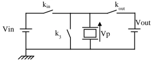
The topology of the converter is represented in FIGURE 1. Once the piezoelectric material starts resonating with a sufficient amplitude, the circuit operates with 6 phases (described below) alternating constant voltage and constant charge steps forming a cycle. If the piezoelectric material were only connected to Vin and Vout, it would have been impossible to have both charge
and energy balance to maintain the resonance and ZVS conditions. That is why a third potential V3 is added to the converter. In the following part, in order to ease the analysis, V3 has been chosen to 0V, the operations are presented in FIGURE 2.
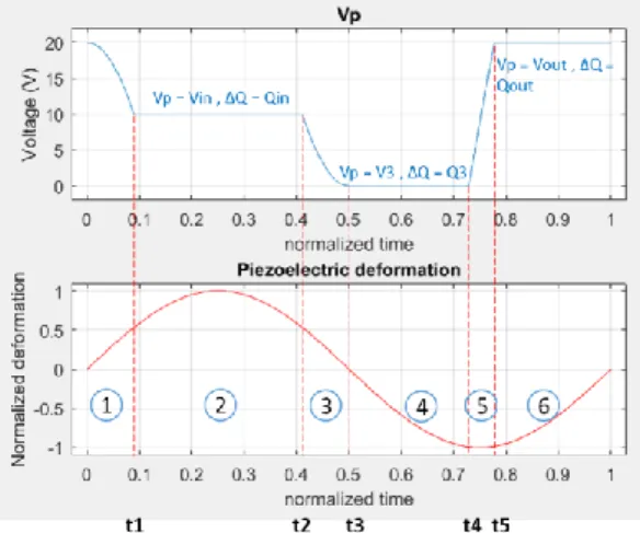
Phase 1, t ϵ [t0-t1]: All the switches are off meaning that the
piezoelectric is isolated of the rest of the circuit and therefore this phase is said to be a constant charge one. Because of the piezoelectric vibrations, Vp drops until reaching Vin at t1 then
k1 is turned on to switch in ZVS mode.
Phase 2, t ϵ [t1-t2]: kin being turned on, Vp is equal to Vin.
This ends when kin is turned off at t2 . t2 is chosen so that Vp will
equal V3 at time t3 (in order to have ZVS mode at t3).
Phase 3, t ϵ [t2-t3]: kin being turned off, Vp decreases until
reaching V3=0V at t3 which corresponds to the maximum of the
piezoelectric deformation and to half of the cycle.
Phase 4, t ϵ [t3-t4]: k3 is turned on and Vp equals V3=0V. k3
is turned off at t4 which is chosen in order to have the desired
output voltage. Indeed a higher t4 value induces an increase of deformation amplitude.
Phase 5, t ϵ [t4-t5]: k3 being turned off, Vp increases until
reaching Vs at t5 then kout is turned on to switch in ZVS mode.
Phase 6, t ϵ [t5-t6]: kout being turned on, Vp is equal to Vs and
the system provides energy to the load. When the piezoelectric deformation is maximum, kout is turned off and a new cycle
begins.
Based on energy conversion consideration, the input source transfers energy to the piezo during phase 2, this one is stored mechanically and restituted to the output source in phase 6.
FIGURE 1.TOPOLOGY OF THE PROPOSED CONVERTER (V3=0V)
This cycle is only possible if three conditions are fulfilled. There must be a charge balance, an energetic balance and the ZVS conditions. Therefore the equations of the system are:
Vin
kin kout
Vout k
Journées Nationales sur la Récupération et le Stockage d’Energie (JNRSE) 2017, Lyon, May 9th-10th 2017
2 𝑄𝑖𝑛 + 𝑄3 + 𝑄𝑜𝑢𝑡 = 0 (1) 𝑄𝑖𝑛 ∗ 𝑉𝑖𝑛 + 𝑄3 ∗ 𝑉3 + 𝑄𝑜𝑢𝑡 ∗ 𝑉𝑜𝑢𝑡 = 0 (2) 𝛥𝑉𝑝ℎ𝑎𝑠𝑒𝑖= 𝑉𝑝𝑝ℎ𝑎𝑠𝑒(𝑖+1)− 𝑉𝑝𝑝ℎ𝑎𝑠𝑒(𝑖−1) , 𝑖𝜖 {1,3,5) (3) where Qin, Q3 and Qout are respectively the charge transfer during the phase 2, 4 and 6. In our case of study, V3=0. The waveforms of Vp and the piezoelectric deformation with the different phases are illustrated in FIGURE 2. With this cycle and this strategy of control, the gain of the converter is not limited to a single value thanks to the possibility to adjust the phases durations and since the switching frequency remains close to the resonance frequency, the efficiency stays high for a large range of loads.
FIGURE 2.PRESENTATION OF A STEP UP CYCLE
III. CARACTERISATION OF THE MATERIAL
The choice of the transducer is a fundamental issue and it must be characterized. Both an excellent quality and coupling factor are necessary. A classical model of piezoelectric resonators is used and described in FIGURE 3.A. The equivalent circuit is composed of two branches. One is composed of the blocked capacitor Cp which represents the capacitive nature of the piezoelectric outside the resonance frequency. The other one describes the mechanical behavior: R represents the losses, L the mass and C the material stiffness. At the resonance frequency (fs), all the current goes through the mechanical branch and the impedance only equals R (because of the L-C resonance).The frequency where the impedance of the two branches is maximal is called the anti-resonance (fp). The typical appearance of the impedance is represented in FIGURE 3.B. The equivalent parameters, the coupling and the quality factor can be derived from the Bode diagram of the material got from an impedance analyzer. With this method, a suitable PZT disk (radius of 10 mm and thickness of 1mm) with promising performances was found: the mechanical resistance is very small (less than 1 Ω) the quality factor is around 1570 and the coupling factor is 0.73 with a 110 kHz resonance frequency. The difference between the measured impedance and the RLC model around the resonance is very small (less than 5%) which validates it.
FIGURE 3. A. RESONATOR ELECTRICAL MODEL B.IMPEDANCE DIAGRAM
IV. SIMULATION RESULTS
A simulation of the global converter was performed in Matlab / Simulink. The system is driven with a finite state machine where a state corresponds to a phase of the cycle. The piezoelectric material characterized in part III is used for the simulation. A RC parallel load is taken: the load capacity equals 440 nF and R is derived from the desired output power. The results show the excellent performances of the converter in perfect agreement with the analytical model which is developed from Eq.(1), Eq.(2) and Eq.(3). For a 10V-20V step-up converter, the simulated efficiency is higher than 98% for 0.5W and higher than 96% for 1W. This efficiency decreases when the output power increases because of supplementary Joule losses caused by the higher resonant current. It can be seen with FIGURE 4. that the system is stabilized after 3 ms with a very high efficiency. At the very beginning, the energy provided by the source is clearly higher than the one transmitted to the output enabling an increase of the amplitude of the resonance of the material.
FIGURE 4.SIMULATION OF A 10V-20V STEP-UP CONVERTER
V. CONCLUSION
A new resonant DC-DC piezoelectric converter is introduced. At each period, energy is taken from the source, stored mechanically and restituted to the output. The high quality factor and coupling of some piezoelectric transducers enable to have very attractive efficiency for different output voltage gains and for different output powers due to ZVS operations. The next step is to build a prototype to fully validate the principle. Since there is no more inductance, this converter could be integrated in silicon and respond to the needs of low power and small dimensions applications like energy harvesting systems.
REFERENCES
[1] D. Vasic and F. Costa, “Applications des éléments piézoélectriques en électronique de puissance,” Tech. L’ingénieur Compos. Act. En
Électronique Puissance Tech. L’ingénieur, pp. 235–24, 2011.
[2] S. Moon and J.-H. Park, “High Power DC–DC Conversion Applications of Disk-Type Radial Mode Pb(Zr,Ti)O$_{3}$ Ceramic Transducer,” Jpn. J.