Control-Structure Interaction Mitigation for
NASA’s Gateway
by
Daniel Christopher Reynolds
B.S. Astronautical Engineering
United States Air Force Academy, 2017
Submitted to the Department of Aeronautics and Astronautics
in partial fulfillment of the requirements for the degree of
Master of Science in Aeronautics and Astronautics
at the
MASSACHUSETTS INSTITUTE OF TECHNOLOGY
June 2019
© Massachusetts Institute of Technology 2019. All rights reserved.
Author . . . .
Department of Aeronautics and Astronautics
June 7, 2019
Certified by . . . .
Kerri Cahoy
Associate Professor of Aeronautics and Astronautics
Thesis Supervisor
Certified by . . . .
Ravi Gondhalekar
The Charles Stark Draper Laboratory, Inc.
Technical Supervisor
Accepted by . . . .
Sertac Karaman
Associate Professor of Aeronautics and Astronautics
Chair, Graduate Program Committee
Control-Structure Interaction Mitigation for NASA’s
Gateway
by
Daniel Christopher Reynolds
Submitted to the Department of Aeronautics and Astronautics on June 7, 2019, in partial fulfillment of the
requirements for the degree of
Master of Science in Aeronautics and Astronautics
Abstract
The Gateway is an advanced National Aeronautics and Space Administration (NASA) concept for a multi-module space station to be placed in a near rectilinear halo orbit around the Moon sometime in the next decade. The first module of the Gateway is known as the Power and Propulsion Element (PPE), and is set to launch in 2022. As the station’s first module, the PPE will be responsible for providing the Gateway with “electrical power, communications, attitude control, orbit maintenance, and the ability to change orbits” [16]. Control of the Gateway represents a complicated and unique control problem due to the spacecraft’s status as a large, multi-modular space-craft; it will have multiple dominant structural modes from its comprising elements: modules, external payloads, solar arrays, a robotic arm, visiting spacecraft, etc [31]. Other spacecraft in this class include the Space Shuttle, the Mir space station, and the International Space Station (ISS). The field that pertains to the “coupling” of control inputs and the resultant structural dynamics is known as “Control-Structure Inter-action (CSI)” [22], and developing CSI mitigation strategies from induced propulsive and non-propulsive actuation has become an important objective for control systems engineers working on large, flexible space structures today. The current standard for CSI management is evident in the recently retired Space Shuttle’s flight control sys-tem: a phase-plane attitude control loop with notch filters on the feedback channel that enabled docked operations with the Mir space station and the ISS. However, when unconstrained by the Shuttle’s architecture and freed to investigate more mod-ernized and adaptable control methods, additional options arise as feasible candidates for Gateway CSI mitigation. For example, a Linear Quadratic Regulator (LQR) pro-vides the basis for individual state vector cost weighting, so that steps can be taken to more directly target the vibrations resulting from multiple structural elements. A Frequency Weighted Linear Quadratic Regulator (FWLQR) extends the functionality of a LQR by enabling the direct penalization of specified frequencies in order to shape the system’s dynamic responses. The Model Predictive Control (MPC) optimization-based approach supplements the frequency-weighted LQR by adding input and output constraint-handling capabilities. Out of all of the CSI mitigation strategies evaluated,
MPC appears to be the optimum candidate for large, flexible space structure CSI mit-igation for its adaptability, flexibility, and relative performance.
The views expressed in this thesis are those of the author and do not reflect the official policy or position of the United States Air Force, Department of Defense, or the U.S. Government.
Kerri Cahoy
Associate Professor of Aeronautics and Astronautics Thesis Supervisor
Ravi Gondhalekar
The Charles Stark Draper Laboratory, Inc. Technical Supervisor
Acknowledgments
“Kahuna Nui Hale Kealohalani Makua”
It will forever be impossible to convey the immense gratitude and love that I feel for the countless family, friends, colleagues, mentors, and supporting organizations that have been so instrumental in allowing me to become the person that I am today, and consequently, to produce this thesis. What follows is a dedication to all those who made this possible. From the bottom of my heart, I thank you.
First and foremost, I want to provide my immeasurable thanks to the United States Air Force, the Massachusetts Institute of Technology, the Charles Stark Draper Laboratory, the United States Air Force Academy, and the Draper Fellow Program for many of the most profound opportunities in my life thus far. Thank you for investing so much time and energy into making me into a better person. You took a chance on me when you didn’t have to, and for that I am extraordinarily thankful. Through you, I have learned valuable lessons, developed incredible relationships, and have grown immensely.
Next, I wanted to thank all of the mentors at Draper that provided me with their support over the past two years. To the Draper Fellow program managers Dr. Sheila Hemami and Mrs. Martha Porter, thank you so much for accepting me into this incredible program and organization, and for being so supportive throughout my two year-long tenure. To my division leader Dr. Diane Mills and my group leader Dr. Louis Breger, thank you for taking me into the Guidance and Control Group, and for allowing me to work and grow side-by-side with some of the most dedicated people that I have ever met. To Mr. Michael Martin, Mr. Sagar Bhatt, Dr. Phil Hattis, Dr. Neil Appleby, Dr. Leena Singh and Dr. Jiann-Woei Jang: thank you for the crucial feedback that you offered me in the early stages of my research; it most certainly helped to shape the direction that I ultimately took. Finally, to Mrs. Michelle Pelersi, Dr. Seamus Tuohy, and other members of the Draper education office who supported this project at a high-level: thank you for giving me the freedom to be creative and for the opportunity to pursue a research topic that I was truly passionate about.
To my advisor Dr. Kerri Cahoy, thank you so much for your consistent support over the past few years. I will always remember you for your limitless enthusiasm and for your altruistic desire to help your students achieve success. You inspire me with your work ethic and your passion for teaching. And of course, to Dr. Ravi Gond-halekar, my technical supervisor at Draper: from evening philosophical discussions to inspiring stories about flight, thank you so much for being approachable, supportive, and encouraging throughout my entire tenure at Draper. Your technical insight and your kind, patient nature has enabled a strong backbone for this thesis. It is needless to say that you have greatly enabled my success at MIT.
To my family: mom and dad, you both are and have been two of my best friends. It’s so difficult to convey my love and appreciation for you both in a few short sen-tences, but I want to thank you so much for always being there for me, no matter what. Benedikt, it’s been a blessing having you so close by. Thank you for some of
the most enlightening conversations that I’ve ever had, and for our transformation from siblings to true friends. You inspire me to continue to explore my creative side! Johnny, you’ve always been one of my biggest role models. Thanks for always being a voice of reason, and for the constant reminders to always learn, grow, and focus on those beautiful traits of love for one another and for yourself. To my sister Rachel: I’m so grateful for the strong bond that we share. Thank you for being someone that I could talk to for just about anything and everything, and for your dual role as a loving sister and a strong mentor.
Ultimately, this thesis is dedicated to all individuals: past, present, and future, who have, continue to, and will in times to come give their hearts, minds, and spirits to the exploration of space. Thank you for your sacrifice, love, passion, and relentless pursuit of the globally unifying dream to extend our human hands outwards into the universe. You are my inspiration.
Contents
1 Introduction 18
1.1 Motivation . . . 18
1.2 Defining “Control-Structure Interaction” (CSI) . . . 19
1.3 Introduction to NASA’s Gateway . . . 24
1.3.1 PPE Requirements . . . 27
1.3.2 Gateway Deployment and Operational Orbit . . . 31
1.4 Chapter Conclusion . . . 34
2 Case Studies 35 2.1 Simulation Time Space . . . 36
2.2 CSI Mitigation Strategy Actuation Capabilities . . . 36
2.3 Orbital Maneuvers: Turn-to-Burn . . . 39
2.4 Case Study 1: Translation . . . 41
2.5 Case Study 2: Attitude Control . . . 43
2.6 Chapter Conclusion . . . 44
3 Simulation Environment 46 3.1 Linear Time-Invariant (LTI) State-Space Systems . . . 47
3.1.1 Translational LTI System . . . 49
3.1.2 Rotational LTI System . . . 52
3.2 Actuator Input Values . . . 58
3.2.1 Solar Electric Propulsion (SEP) Actuation . . . 58
3.2.2 Reaction Control System (RCS) Actuation . . . 59
4 Summary of Control Methodologies 60
4.1 Phase Plane Controller . . . 60
4.2 Proportional-Integral-Derivative (PID) Controller . . . 65
4.2.1 Proportional Control Action . . . 66
4.2.2 Integral Control Action . . . 66
4.2.3 Derivative Control Action . . . 67
4.3 Linear Quadratic Regulator (LQR) . . . 67
4.4 Frequency Weighted Linear Quadratic Regulator (FWLQR) . . . 68
4.5 Model Predictive Control (MPC) . . . 71
5 Simulation Results 74 5.1 Case Study 1: Translation . . . 74
5.1.1 Phase Plane Controller . . . 75
5.1.2 PID . . . 79
5.1.3 LQR . . . 83
5.1.4 FWLQR . . . 90
5.1.5 MPC . . . 95
5.2 Case Study 2: Attitude Control . . . 106
5.2.1 Phase Plane Controller . . . 106
5.2.2 PID Controller . . . 111 5.2.3 LQR . . . 113 5.2.4 FWLQR . . . 116 5.2.5 MPC . . . 118 6 Conclusion 122 6.1 Contribution . . . 122 6.2 Recommendations . . . 124 6.3 Future Work . . . 125
6.3.1 Advanced Model Development . . . 125
6.3.2 Computational Load Analyses . . . 126
Acronyms
BAA Broad Agency Announcement
CSA Canadian Space Agency
CMG Control Moment Gyro
CONOPS Concept of Operations
CR3BP Circular Restricted Three Body Problem
CSI Control-Structure Interaction
CSM Command and Service Module
DAP Digital Autopilot
DFT Discrete Fourier Transform
DRO Distant Retrograde Orbit
ESA European Space Agency
EVA Extravehicular Activity
FCS Flight Control System
FWLQR Frequency Weighted Linear Quadratic Regulator
GNC Guidance, Navigation, and Control
ISS International Space Station
IUS Inertial Upper Stage
JAXA Japan Aerospace Exploration Agency
JPL Jet Propulsion Laboratory
LLO Low Lunar Orbit
LM Lunar Module
LQG Linear-Quadratic-Gaussian
LQR Linear Quadratic Regulator
LTI Linear Time-Invariant
MIMO Multiple Input Multiple Output
MIT Massachusetts Institute of Technology
MPC Model Predictive Control
MPCV Multi-Purpose Crew Vehicle
NASA National Aeronautics and Space Administration
NRHO Near Rectilinear Halo Orbit
OMS Orbital Maneuvering System
PDP Plasma Diagnostic Package
PID Proportional-Integral-Derivative
PPE Power and Propulsion Element
PRCS Primary Reaction Control System
RFI Request for Information
RMS Remote Manipulator System
ROSA Roll-Up Solar Array
RS Russian Segment
RTLS Return to Launch Site
RW Reaction Wheel
SEP Solar Electric Propulsion
SISO Single Input Single Output
SLS Space Launch System
SMA Safety and Mission Assurance
TDRS-1 Tracking and Data Relay Satellite-1
TLI Trans-Lunar Injection
Nomenclature
˙
𝜃𝑃 The PPE’s angular velocity relative to its point of origin in degrees/second
˙
𝜃𝑅 The solar array’s angular velocity relative to its point of origin in degrees/second
˙𝑥𝑃 The PPE’s velocity relative to its point of origin in m/s
˙𝑥𝑅 The solar array’s velocity relative to its point of origin in m/s
𝛾 Interval in which the finite difference is calculated over for 𝑢𝐷
𝜅 The value of the spring coefficient in N/m
𝜈 The value of the viscous damping coefficient in N /(m/s)
𝜔𝑒𝑟𝑟𝑜𝑟𝐵 Error rate as represented on the phase plane
𝜏 The torque matrix in N · m
𝜃𝑒𝑟𝑟𝑜𝑟𝐵 Error as represented on the phase plane
𝜃𝑃 The angular displacement of the PPE from its point of origin in degrees
𝜃𝑅 The angular displacement of the solar array from its point of origin in degrees
𝐴 The state transition matrix
𝐵 The input distribution matrix
𝑏 The extended length of the rectangular solar array wing flush with the y-axis of rotation in m
𝐶 The output matrix of the specific model
𝐷 The feedforward matrix
𝑒(𝑘) Error between commanded output and current input
𝑓 Frequency in Hz
𝑓+ Reaction Control System (RCS) jet “on” notation on the phase plane
𝑓− RCS jet “off” notation on the phase plane
𝐼𝑥 The mass moment of inertia about the x-axis, in kg · m2
𝐼𝑧 The mass moment of inertia about the z-axis, in kg · m2
𝐽 Cost function for LQR, FWLQR, and MPC control methodologies
𝐽𝑃 The mass moment of inertia of the PPE in kg · m2
𝐽𝑅 The mass moment of inertia of the solar array in kg · m2
𝐾𝐷 Scalar controller gain for PID derivative control action
𝐾𝐹 𝑊 𝐿𝑄𝑅 FWLQR gain matrix
𝐾𝐼 Scalar controller gain for PID integral control action
𝐾𝐿𝑄𝑅 LQR gain matrix
𝐾𝑃 Scalar controller gain for PID proportional control action
𝑚 The number of outputs in the output vector
𝑚𝑃 The mass of the PPE in kg
𝑚𝑅 The mass of the solar array in kg
𝑁 Prediction horizon
𝑃 Solution of the algebraic Riccati equation
𝑝 The number of inputs in the input vector
𝑄 State vector cost function weighting variable for LQR, FWLQR, and MPC control methodologies
𝑄𝑂𝑢𝑡𝑝𝑢𝑡 Output vector cost function weighting variable for LQR, FWLQR, and MPC
control methodologies
𝑅 Input vector cost function weighting variable for LQR, FWLQR, and MPC control methodologies
𝑆 Weighting vector on output constraints
𝑇 The thrust matrix in N
𝑢(𝑘) The discrete-time input vector
𝑢(𝑡) The continuous-time input vector
𝑢𝐷 Derivative control action element for the PID controller
𝑢𝐼 Integral control action element for the PID controller
𝑢𝑃 Proportional control action element for the PID controller
𝑉 Terminal cost; weighting variable unique to finite-horizon MPC
𝑥(𝑘) The discrete-time state vector
𝑥(𝑡) The continuous-time state vector
𝑥𝑃 The displacement of the PPE from its point of origin in m
𝑥𝑅 The displacement of the solar array from its point of origin in m
𝑦(𝑘) The discrete-time output vector
𝑧𝑘 Difference between minimum and maximum output constraints of the
List of Figures
2-1 “Turn-to-Burn” Maneuver Visualization . . . 41
3-1 Linear LTI System: Control-relevant Dynamics Model . . . 49
3-2 Rotational LTI System: Control-relevant Dynamics Model . . . 52
3-3 Cylinder with 3-D Axes of Rotation . . . 53
3-4 Rectangle with 3-D Axes of Rotation . . . 54
3-5 Cylinder and Rectangle with 3-D Axes of Rotation . . . 54
5-1 Case Study l (Phase Plane): PPE Trajectory, Solar Array/PPE Rela-tive Displacement, and RCS Control Input Plots . . . 76
5-2 Case Study l (Phase Plane) Portrait . . . 77
5-3 Case Study l (Phase Plane): PPE Trajectory, Solar Array/PPE Rela-tive Displacement, and Control Input Plots without Notch Filters . . 78
5-4 Case Study l (Phase Plane): Spectral Discrete Fourier Transform (DFT) Content of the Solar Array/PPE Relative Displacement . . . 79
5-5 Case Study l (PID): Control Objective and Control Input Simulation Output . . . 81
5-6 Case Study l (PID): Spectral Simulation Output . . . 82
5-7 Case Study l (LQR): Control Objective and Control Input Simulation Output for Scenario #1 . . . 85
5-8 Case Study l (LQR): Control Objective and Control Input Simulation Output for Scenario #2 . . . 87 5-9 Case Study l (LQR): Control Objective and Control Input Simulation
5-10 Case Study l (LQR): Spectral Simulation Output Comparison between Scenario #1 and #2 . . . 89 5-11 Case Study l (LQR): Spectral Simulation Output Comparison between
Scenario #1 and #2 . . . 90 5-12 Case Study l (FWLQR): Band Pass Filter Centered at 0.1 Hz . . . . 91 5-13 Case Study l (FWLQR): Control Objective and Control Input
Simu-lation Output for Scenario #1 . . . 92 5-14 Case Study l (FWLQR): Control Objective and Control Input
Simu-lation Output for Scenario #2 . . . 94 5-15 Case Study l (FWLQR): Spectral Content Relative Displacement
Out-put Comparison for Scenarios #1 and #2 . . . 95 5-16 Case Study l (MPC): Control Objective and Control Input Simulation
Output for Scenario #1 . . . 97 5-17 Case Study l (MPC): Control Objective and Control Input Simulation
Output for Scenario #2 . . . 99 5-18 Case Study l (MPC): Control Objective and Control Input Simulation
Output for Scenario #3 . . . 101 5-19 Case Study l (MPC): Control Objective and Control Input Simulation
Output for Scenario #3 with Frequency Weighting “On” . . . 102 5-20 Case Study l (MPC): Control Objective and Control Input Simulation
Output for Scenario #4 . . . 104 5-21 Case Study l (MPC): Control Objective and Control Input Simulation
Output for Scenario #4 with Output Constraints . . . 105 5-22 Case Study 2 (Phase Plane): Control Objective and Control Input
Simulation Output for Scenario #1 . . . 107 5-23 Case Study 2 (Phase Plane): Two-Dimensional Portrait for Scenario #1109 5-24 Case Study 2 (Phase Plane): Control Objective and Control Input
Simulation Output for Scenario #2 . . . 110 5-25 Case Study 2 (Phase Plane): Spectral Content Output Comparison
5-26 Case Study 2 (PID): Control Objective and Control Input Simulation Output . . . 112 5-27 Case Study 2 (PID): Spectral Content Output . . . 113 5-28 Case Study 2 (LQR): Control Objective and Control Input Simulation
Outputs . . . 114 5-29 Case Study 2 (LQR): Spectral Content Output . . . 115 5-30 Case Study 2 (FWLQR): Control Objective and Control Input
Simu-lation Outputs for Scenario #1 . . . 117 5-31 Case Study 2 (FWLQR): Control Objective and Control Input
Simu-lation Outputs for Scenario #2 . . . 118 5-32 Case Study 2 (FWLQR): Spectral Content Comparison for Scenario
#1 and #2 . . . 119 5-33 Case Study 2 (MPC): Control Objective and Control Input Simulation
Chapter 1
Introduction
1.1
Motivation
On 23 June 2011, a Russian Progress cargo vehicle (NASA identifier: 43P) was on approach to dock with the ISS [32]. To prepare for the docking, the ISS was conduct-ing a 180° slewconduct-ing maneuver usconduct-ing thrusters onboard its Zvesda service module and an already docked Progress cargo vehicle. During the slewing maneuver, the control system of the ISS’s Russian Segment (RS) falsely detected that two of the thrusters charged with yaw actuation onboard the Zvesda service module (Manifold 2 thrusters #12 and #13 visualized in Figure 3 of [32]) had failed. The control system of the ISS’s RS then reverted to alternate thrusters (Manifold 1 thrusters #18 and #19 visualized in Figure 3 of [32]) in an effort to complete the slewing maneuver.
The failure of the control logic resulted in unintentional thruster firings that yielded a 10-minute-long period of high acceleration. This event was considered by NASA and the Russian space agency to be one of the “most severe” high acceleration events in the ISS’s operational history [32]. Significantly high loads were noticed in multiple ISS structural elements that were, at times, 25% higher than those experi-enced during pre-flight analyses.
Although no structural damage was incurred, the event prompted an extraordi-narily valuable expansion of risk awareness for the ISS program [32]. Both NASA and Russian space officials “realized that the ISS had been flying at risk of catastrophic
structural loads caused by thruster firings, and those loads had the potential to be much higher than those experienced” [32] during the 23 June 2011 event. One of the concluding statements in the paper describing the event was the realization that the ISS had experienced a severe “control-structure interaction” problem [32].
1.2
Defining “Control-Structure Interaction” (CSI)
The discipline of CSI is defined by NASA as the “detrimental closed-loop coupling between structural modes and a feedback control system” [65]. Simply defined, CSI is the coupling between the resultant dynamic structural responses of a physical system to control inputs. The field of CSI emerges from an intersection of control systems engineering and structural engineering. From ground-based systems such as automobiles [61] to underwater vehicle-manipulator systems [20], managing the dynamic responses of physical systems as a result of control inputs is an important discipline that a control systems engineer must consider to ensure system performance and survivability.
In the realm of human spaceflight, the 23 June 2011 event is considered to be one of the most severe CSI issues pertaining to excessive structural loads generated by unintentional thruster firings. To the author, this event highlights the complexities of CSI management and mitigation for large space structures like the ISS. The ISS is unique when compared to other spacecraft (both current and historical) for its sheer size and mass. The ISS is comprised of many structural elements, including: 16 modules, eight solar arrays covering an area of approximately 2,500 m2, truss segments, pressurized mating adapters, and more [1] [13] [4] [13]. The image available at [13] depicts an exploded view of the ISS to help the reader in visualizing the structural complexity of the 357 foot (end-to-end) space station [12].
Large and flexible space structures are sensitive to excitation, due to the existence of various bending modes and resonant frequencies that are inherent to the space-craft’s structural elements. The resultant motion stemming from control actions can excite these modes of vibration, which can lead to instabilities and can induce loads, which is what occurred in the 23 June 2011 event. The same report that described
the ISS event [32] included a snapshot of some of the ISS’s sensitive frequencies from 0 Hz to 0.033 Hz, and some of the sources of these frequency spikes [32]. This snapshot is provided in [32] as Figure #26.
To avoid exciting the various resonant frequencies associated with the structural elements of spacecraft, control systems engineers need to develop methods and logic within control systems to avoid excitations and significant structural stresses. Dur-ing NASA’s Gemini space flight program of the 1960s, engineers used a notch filter to remove troublesome portions of the spectrum on the sensor feedback channels, thereby preventing the controller from acting upon those frequencies, and thus miti-gating load-inducing activity during docked operations between the Gemini spacecraft and the uncrewed Agena target vehicle [65]. The first bending mode of the docked spacecraft was at 5 Hz, so a notch filter was used to sustain a gain margin of 6 dB at that frequency [65], thus mitigating potentially destabilizing spectral content at that frequency. During the Apollo-era, similar methods were used when the Apollo Command and Service Module (CSM) was docked with the Lunar Module (LM) to avoid the excitation of certain frequencies [69]. The Space Shuttle also employed a notch filter-based approach to remove the pathological frequencies from the feedback signal that could cause the control system to excite frequencies of concern (e.g., the frequencies of the dominant structural modes) during docked operations with the Mir space station, in addition to assembly and docked operations with the ISS. More details on the Space Shuttle’s CSI mitigation strategy are presented in Section 4.1 of this thesis.
CSI, simply defined, is the coupling between the resultant dynamic structural responses of a physical system to control inputs. For spacecraft, this can include both intended inputs such as the various means of propulsion and attitude control, and external inputs such as solar radiation pressure, outgassing, and forces/torques incurred through docking with other spacecraft. As the 23 June 2011 incident em-phasized, significant care must be placed towards the development of an effective CSI mitigation strategy that can not only manage the intended and external inputs to a system, but one that can also withstand worst-case scenarios. This is especially
important for large, flexible spacecraft with multiple modes of vibration like the ISS. Developing a CSI mitigation strategy that can mitigate potentially destabilizing vi-brations is crucial for the mission success of any future spacecraft. NASA’s Gateway is one such spacecraft.
In Chapter 1 of this thesis, the Gateway is introduced from both a programmatic (Section 1.3) and a technical (Sections 1.3.1 and 1.3.2) point of view. The program-matic review recaps the state of the Gateway project at the time of the writing of this thesis. A technical review is also presented, which consists of two primary com-ponents; the first component is a review of the high-level requirements published by NASA in the summer of 2018 in regards to the Gateway’s first module, the PPE. The second component is a review of the operational orbit that the PPE will presumably be deployed into, and the family of orbits that it will potentially operate in (while simultaneously growing in size to represent the full Gateway stack) (Section 1.3.2). A primary objective of Chapter 1, beyond introducing the Gateway as a program, is to establish its nominal operating parameters. By presenting the PPE’s requirements and information about its insertion orbit, the reader can gain an insight into vari-ous ΔV, energy, and maneuvering requirements that the Gateway will be expected or required to subscribe to. Additionally, by understanding the nominal operating parameters of the PPE, two case studies representative of the Gateway’s planned orbital maneuvers can be crafted to test a pre-selected array of candidate CSI mit-igation strategies. The cases of orbital translations and attitude control maneuvers (i.e., orbital station-keeping and transitions between various orbits) can be crafted to test a pre-selected array of candidate CSI mitigation strategies, which is the subject of Chapter 2.
Chapter 2 applies the programmatic and technical data presented in Chapter 1 to develop the specific case studies that detail the maneuvers to be performed by each CSI mitigation strategy. First, various assumptions are made in regards to the simulation duration of each of the case studies (Section 2.1), with a follow-on discussion on the actuation limitations per CSI mitigation strategy (Section 2.2). An introduction is given to the “Turn-to-Burn” strategy that will characterize the
majority of the Gateway’s maneuvers throughout its lifetime in Section 2.3. The “Turn-to-Burn” strategy is divided into three distinct maneuvers: an initial rotation to the burn attitude, the burn itself, and a follow-on rotation to either the original or a new spacecraft attitude. Case Study #1 is crafted to evaluate the PPE’s dynamics, with an extended solar array, under a 1.5-meter translational burn in one axis (Section 2.4), and Case Study #2 is crafted to model an 180° rotation about one axis (Section 2.5). The case studies establish the maneuvers that each CSI mitigation strategy will be evaluated against, and make up one part of the simulation space. The second part refers to the linear LTI models that will define the structural dynamics of the PPE and its solar array for both the translational and rotational models, and is presented in 3.
Chapter 3 introduces the translational (Section 3.1.1) and rotational (Section 3.1.2) models that will define the Gateway model used in the simulation space. The translational and rotational models are representative of the PPE with one extended, large, flexible solar array. Section 3.2 provides a discussion characterizing the max-imum and minmax-imum thrust and torque values that will be used as control inputs in the translational and rotational models.
Chapter 4 introduces each of the five CSI mitigation strategies that are tested in the simulation environment against each of the three case studies. These strategies, along with a brief description, are provided in the following enumerated list:
1. Phase Plane; Section 4.1: Phase plane controllers operate with respect to a two-dimensional Cartesian coordinate grid, with error presented on the hor-izontal axis and error rate presented on the vertical axis. The error and error rates are calculated from differences between commanded attitudes and actual attitudes. Control engineers design switching lines on this grid which, when error vs. error rate boundary lines are exceeded, trigger the “on” condition of binary “on-off," or “bang-bang” thrusters to drive the error and error rate back to within acceptable margins. This method was used for the Space Shuttle’s on-orbit Digital Autopilot (DAP).
2. PID Control; Section 4.2: PID is a classical control method that is cited as being the most common control method used for control applications today [75]. The control action is composed of three control components: a proportional component that considers control action based upon the current error (i.e., the difference between the commanded attitude and the current attitude), an integral component that considers previous error, and a derivative component that considers future error [74].
3. LQR; Section 4.3: The LQR is an optimal controller that, given a set of user-specified weighted parameters that balance weights on system states and inputs, incorporates a cost function to ultimately compute a state-feedback gain for computing a control input that minimizes said cost function [30] [45].
4. FWLQR; Section 4.4: The FWLQR control method builds off of the founda-tions provided in LQR theory, by supplementing the base capabilities of LQR with the ability to penalize frequencies of interest.
5. MPC; Section 4.5: MPC is an effective strategy for constrained control prob-lems. One can accommodate known constraints on control inputs. Furthermore, one can impose desired constraints on the system’s states and/or outputs.
Chapter 5 implements these control methodologies as representative translation and attitude controllers. Section 5.1 evaluates the performance of each CSI mitigation strategy for Case Study #1, and Section 5.2 evaluates their performance for Case Study #2. Each CSI mitigation strategy is evaluated for its ability to accomplish the primary control objective of completing the translation or attitude change maneuver, and the secondary control objective of mitigating potentially destabilizing oscillations. Chapter 6 concludes with a brief recap of the thesis’s contribution in Section 6.1. Section 6.2 provides a discussion of the simulation results procured in 5, and provides the author’s recommendation on the highest-performing control strategy in the context of the simulations performed. Section 6.3 concludes the thesis with a few topic areas that can be further developed.
1.3
Introduction to NASA’s Gateway
The Gateway is an advanced NASA concept for a multi-module space station to be placed in lunar orbit in the early 2020s [42]. As humanity’s first long-term crewed/uncrewed presence in lunar orbit, the Gateway draws its appeal from being able to serve as a multipurpose lunar outpost in cislunar space: its planned positioning in lunar orbit is expected to enable routine deployments to a lunar research station, and serves as a crucial element in NASA’s plan to expand humanity’s presence to Mars [42].
The concept for a lunar space station has existed for some time, but the 2019 NASA fiscal year budget request was the first to specifically allocate funding for the Gateway project, recommending $504.2 million [9]. The final budget approved by Congress in February 2019 was the first to allocate funding specifically for the Gateway, but had decreased this value to $450 million [24] [26]. In comments following the release of the budget request, then acting NASA administrator Robert Lightfoot cited the relationship of the requested Gateway funding with that of the current political administration’s efforts to expand humanity’s presence to the Moon, Mars, and to other destinations beyond Earth [56]. These efforts, as made evident in a White House memorandum issued a few months prior, amended the previous National Space Policy of the United States to putting the United States in a position to “lead the return of humans to the Moon for long-term exploration and utilization, followed by human missions to Mars and other destinations” [40].
In response to this directive, NASA released a Request for Information (RFI) specific to the first Gateway module, the PPE in July 2017 [5] [7]. The purpose of the PPE is to provide a variety of fundamental capabilities to the rest of the multi-module Gateway stack. The following bulleted list was taken verbatim from [11], and describes these capabilities:
• “Obtain data to understand the health and performance of the system” [11] • “Obtain data to support future operations and sustaining engineering including
• “Provide power to the Gateway” [11]
• “Provide transportation for the Gateway between cislunar orbits and perform any needed orbital maintenance” [11]
• “Provide attitude control for the Gateway in multiple configurations with and without visiting vehicles such as Orion” [11]
• “Provide Gateway communications with Earth, visiting vehicles, and the lunar surface, and act as a relay with Earth for visiting vehicles, in support of extra-vehicular activity (EVA) and lunar surface operations.” [11]
• “Support utilization experiments and technology demonstrations provided by NASA, international, or commercial partners” [11]
The July 2017 RFI’s purpose was therefore to explore “the possibility of a cost ef-fective development effort” for the PPE, by inviting companies to provide descriptions of ability, conceptual schedules, and summaries of technical development approaches specific to the construction of the PPE [5]. Within the RFI, 16 fundamental technical capabilities were listed to guide these companies in their attempts to secure NASA’s support to conduct concept studies that would lead to various PPE concepts [5]. These fundamental design reference capabilities would come to form the foundation of an initial rendition of the PPE’s higher level requirements, which were released in a draft Broad Agency Announcement (BAA) nearly one year later (June 2018) [53]. In November 2017, NASA announced that the Boeing Company, Lockheed Martin, Orbital ATK Incorporated, the Sierra Nevada Corporation, and Space Systems/Loral were selected to conduct studies into a PPE concept design [37].
The PPE BAA can best be defined as “a full and open competition soliciting proposals from United States Industry that could lead to potentially one or more technology demonstration contract awards for an industry/NASA partnership for the development and spaceflight demonstration of a PPE” [11]. As previously mentioned, the contents of the BAA include high level requirements that industry could use to begin their concept design process, but it also includes additional elements such as
a notional summary schedule (with a predicted PPE launch in 2022), government furnished equipment information, and additional reference materials that potential industrial partners could use [15].
In September 2018, NASA released an updated version of the BAA as a formal solicitation for research and development contracts that would help in enabling the development of a PPE, with a proposal due date of November 2018 [11]. NASA released the formal BAA in September 2018, and is currently in the process of eval-uating PPE industry proposals. In February 2019, NASA released a memorandum stating that the procurement process was still ongoing [58]. NASA, in its September 2018 BAA, stated that “offeror[s] shall propose a schedule with a launch date [of] no later than September 2022 with a demonstration to last no longer than one year in duration to be completed no later than September 2023” [11], although in its February 2019 update the no-later-than launch date had slipped to 31 December 2022. [58]
In September 2018, NASA released a layout of what the Gateway could look like when fully assembled [31]. The presentation in which this layout was provided also includes descriptions of each of the elements briefed by NASA in the September 2018 presentation [31]. These descriptions and their corresponding elements are presented in the following enumerated list, and were taken verbatim from [31].
1. Power and Propulsion Element (PPE): “Power, communications, attitude control, and orbit control and transfer capabilities for the Gateway” [31]. 2. ESPIRIT: “Science airlock, additional propellant storage with refueling, and
advanced lunar telecommunications capabilities” [31].
3. U.S. Utilization Module: “Small pressurized volume for additional habita-tion capability” [31].
4. Robotic Arm: “Mechanical arm to berth and inspect vehicles, install science payloads” [31].
5. Habitation Module: “Pressurized volumes with environmental control and life support, fire detection and suppression, water storage and distribution” [31].
6. Logistics and Utilization: “Cargo deliveries of consumables and equipment. Modules may double as additional utilization volume” [31].
7. Roll-Up Solar Arrays (ROSAs): 300 kW class solar arrays.
8. Sample Return Vehicle: “A robotic vehicle capable of delivering small sam-ples or payloads from the lunar surface to the Gateway” [31].
9. Airlock: “Enables spacewalks, potential to accommodate docking elements” [31]. 10. Orion Multi-Purpose Crew Vehicle (MPCV): “U.S. crew module with
ESA service module that will take humans farther into deep space than ever before” [31].
On 5 March 2019, NASA published a press release which included an illustration highlighting the international collaboration that will go behind the development of the Gateway [67]. It broke down the international stakeholders that will participate in the Gateway’s development per module [67]. According to this information, NASA, the European Space Agency (ESA), the Japan Aerospace Exploration Agency (JAXA), the Canadian Space Agency (CSA), and the Russian State Corporation for Space Activities (ROSCOSMOS) will be stakeholders in the design of the Gateway stack [67].
1.3.1
PPE Requirements
A list of high level requirements accompanied the BAA in June 2018 that were specific to the PPE [53]. These requirements were published to provide potential industry partners with a high-level understanding of both the purpose and capabilities of the PPE, as desired by NASA. Concurrently, these requirements and the rest of the BAA serve as one of the best public resources on extrapolating information necessary for PPE model and simulation development. Additionally, other elements of publicly releasable information, such as the orbit of the Gateway, allow for the generation of additional assumptions that will help in shaping the simulation environment. The following list is a summary of the most applicable PPE requirements with respect to
the development of a CSI mitigation strategy, and includes some verbatim information taken from the requirements document [53]. Listed alongside these requirements are the official identifiers of requirements that influenced the requirement synopses:
1. Guidance, Navigation, and Control (GNC)
(a) ThreeAxis Attitude Control & Translational Maneuver Authority [53]
-NU-PPE-1415; NU-PPE-1591; NU-PPE-1780; NU-PPE-1506
i. The PPE shall have two onboard propulsive mechanisms available in which to perform three-axis attitude control and to perform transla-tional maneuvers: a RCS monomethylhydrazine-based capability and a 300 kW-class xenon-based Solar Electric Propulsion (SEP) capabil-ity. Additionally, the PPE will have a non-propulsive three-axis atti-tude control capability in the form of Control Moment Gyros (CMGs) and/or Reaction Wheels (RWs).
(b) Free Drift: Zero Forces, Torques [53] - NU-PPE-1843; NU-PPE-1482 i. The PPE shall be capable of flying in a static free drift mode. This
is relevant for docking procedures, as the Gateway will be the target vehicle for all visiting vehicles and incoming modules. These require-ments also highlight the necessity of the flight control system to bring the Gateway to a static and stable state after conducting translational or rotational maneuvers.
(c) PPE Autonomous Operations Demonstration [53] - PPE-1796;
NU-PPE-1893
i. The PPE shall be able to operate autonomously, including with SEP system burns during cislunar orbital transfers, for at least three weeks. Autonomous operations, as defined by NASA in the context of the PPE, includes having a system capable of completing “all PPE func-tions... needed to support the Gateway Mission... without ground controllers in the loop” [53]. This three-week requirement is also em-bedded in the fact that the Gateway is to be uncrewed for extended
periods of time, and may require remote and/or autonomous opera-tions.
(d) Maintenance of Near Rectilinear Halo Orbit (NRHO) [53] -
NU-PPE-1910; NU-PPE-1911; NU-PPE-1923
i. The PPE shall be able to perform orbital maintenance maneuvers with both the SEP and the RCS systems. Orbital maintenance maneuvers are burns required to keep the Gateway in a designated orbit. The Gateway is predicted to require a ΔV of less than 10 m/s per year in regard to orbital maintenance in its NRHO deployment.
(e) Orbital Transfers [53] - 1898; 1914;
NU-PPE-2237; NU-PPE-1897
i. The Gateway shall be capable of performing cislunar orbital transfers with the SEP system. This includes the insertion into a NRHO at the beginning of the PPE/Gateway’s mission with the SEP system. 2. Crew
(a) Crew Vibration Exposure Limits [53] - NU-PPE-1497
i. NASA maintains standards on human factors, habitability, and envi-ronmental health in a document known as NASA-STD-3001 Volume 2 [3]. This document provides insight into a variety of vibration lim-itations on crew members during multiple stages of flight (e.g., pre-flight, sleep periods, maximum exposure guidelines in a 10 minutes time span, etc.) that can be used to influence the development of a CSI mitigation strategy. For example, it is noted that the “maximum frequency-weighted acceleration” that the crew may experience be-tween “0.5 and 80 Hz” in a one-minute-long period is “5.9 𝑚/𝑠2 RMS
(0.6 g RMS)” [3]. Having a capability to manage vibrations related to the physiological requirements of the crew is important.
(a) Flight System Mass [53] - NU-PPE-1702
i. The “PPE... shall not exceed a wet mass of 8000 kg after completion of the spaceflight demonstration” [53].
(b) Exclusion Zones [53] - NU-PPE-1710
i. The Gateway shall be able to actively avoid various “keep-out zones” during operations within its lifetime. A “keep-out zone” is defined as an area that the Gateway will not be able to perform either three-axis attitude control or translational burns in. This includes exclusion areas during crewed Extravehicular Activities (EVAs), operations from a Remote Manipulator System (RMS), visiting vehicles, etc.
(c) In-Space Structural Monitoring - NU-PPE-1873
i. The PPE “shall provide telemetry to monitor and characterize [the] structural dynamic response of the PPE to in-space load events,” such as docking operations, control inputs, and crew activities [53]. Addi-tionally, the requirements state that “it will be important to measure the overall dynamic response to these events for the lifetime of the PPE in order to validate Gateway dynamic models, assess structural health and adjust operations if needed” [53]. Having the ability to measure the overall dynamic response of a system to load-inducing events and to compensate for them is a crucial component that the Gateway’s control system must have.
4. Safety and Mission Assurance (SMA)
(a) Autonomous Hazard Control [53] - NU-PPE-2241
i. “The PPE... shall provide autonomous control of catastrophic haz-ards” [53].
(b) Respond to Loss of Function - Autonomous Safing [53] - NU-PPE-2268 i. The PPE shall be capable of autonomously entering into a safe mode and remaining there for three weeks, in regards to preventing any
catastrophic events to the Gateway or the crew within.
The requirement categories, as summarized above, contain a summary of those requirements that are directly relevant to the design of a CSI mitigation strategy. The control architecture onboard the Gateway should not only be able to accommodate three-axis attitude control and to have translational maneuver authority, but it should also be able to perform in an autonomous capacity, and should be well-equipped to manage a variety of hazards. Additionally, the control architecture of the Gateway should be developed in consideration to a variety of “exclusion zones,” as described in requirement summary 3.b. above [53]. As the Gateway grows and expands, it’s control architecture should be able to consider constraints on controller outputs (e.g., stack displacement from origin, stack rotation, relative displacement of the primary stack with respect to the station’s solar arrays, etc.). Finally, the specific mentioning of the management of vibrations that the crew would be exposed to during flight provides an additional motivation for an effective CSI mitigation strategy. These considerations and takeaways are important, as they contribute to the formulation of various case studies in which to test potential CSI mitigation strategies against in the simulation environment. Ultimately, understanding the programmatic and technical details of the Gateway and the PPE are important, as they are a primary driver behind the motivation, design and choice of a control methodology for CSI mitigation.
1.3.2
Gateway Deployment and Operational Orbit
It is important to understand the orbit that the PPE will be deployed into, and concurrently, the family of the orbits that the Gateway will operate in. Orbits carry with them certain energy requirements associated with initial orbit insertion, station-keeping, and transitions to other orbits. Understanding the orbit of the Gateway is an important step in the creation of the two nominal case studies that the CSI mitigation strategies will be evaluated against.
The PPE will be deployed into a NRHO about the Moon [53]. The NRHO orbit family can be conceptually defined as a family of orbits “with large amplitudes over
either the north or south pole with shorter periods that pass closely to the opposite pole” [68]. The NRHO family of orbits exists because of the L1 and L2 Lagrange points; equilibrium points in space that are solutions to the Circular Restricted Three Body Problem (CR3BP) [29] [34] [25]. The CR3BP dynamical model considers the motion of a massless point (the spacecraft), “under the gravitational influence of the Earth and the Moon” [29]. Solving the CR3BP yields five points of equilibrium: three of which (the unstable three) are located along the Earth-Moon “line” (two of which are the L1 and L2 points, which are visualized in Figure 1 of [29]).
Numerous studies have been made into both the characteristics and advantages of the NRHO family as operational orbits for lunar space stations [68] [71] [29] [25] [51]. One pertinent consideration to the selection of the NRHO family is the ability for crews to access it from Earth given time and fuel constraints. At the time of this thesis’ composition, the most reasonable candidate for crew delivery to a space station in a NRHO is the Orion MPCV, which, after being launched from Earth and inserted into a Trans-Lunar Injection (TLI) orbit, will have enough remaining fuel to achieve a total ΔV of 1250 m/s [68]. The Orion MPCV will be able to support 4 crew members for 21 days at a time [68]. Although ΔV requirements will vary slightly depending on launch dates and mission durations (e.g., if the Orion MPCV could be equipped for longer duration missions), a NRHO was found to be suitable and well within the ΔV and transit time requirements [68]. For a 21-day mission, for example, a crew launching in February 2021 would require the ability to produce a total of 840 m/s of ΔV to ensure a “stay time” of 10.9 days in a NRHO (where “stay time” refers to the amount of time that the crew could remain in a NRHO given the 21-day mission length) [68].
An important mission objective for the Gateway is to enable lunar surface access, so the selected orbit should facilitate this objective. For uncrewed missions from the Gateway, a lander would only require the fuel necessary to produce a ΔV on the order of tens of meters per second to enter into a Low Lunar Orbit (LLO). This value only includes the necessary ΔV to get from the NRHO to the LLO, and does not include the ΔV required to transit from the LLO to the lunar surface. The transfer to the
LLO from the NRHO would, however, require a transfer time of several months [31]. The Gateway could possibly host at least one uncrewed sample return vehicle, which could make use of this minimal fuel benefit [31]. Additionally, there are a variety of other uncrewed spacecraft that could deploy from the Gateway and take advantage of this low ΔV requirement. For crewed spacecraft, the NRHO is the second most preferred orbit to enter into a polar LLO from prior to beginning a powered descent, relative to five other candidate orbits analyzed in [68]. For landings at a polar-based location on the lunar surface, a ΔV of approximately 730 m/s with a total transfer time of 0.5 days will be needed to descend into a polar LLO around the Moon [68]. Approximately the same ΔV and time constraints apply for ascents back into a NRHO as well [68]. If a lunar lander would like to land on the equator, a descent into an equatorial LLO would require approximately 900 m/s of ΔV, which also holds true for the ascent back into the NRHO [68]. Figure 5 from [68] shows approximate ΔV costs for descents from a NRHO into a LLO summed with the corresponding ascents back into NRHO as a function of LLO orbital location.
Additional advantages to positioning the Gateway in a NRHO include a relatively low cost of station-keeping, or ΔV required to maintain the Gateway’s positioning in that particular orbit. For NRHOs about the L2 point specifically, an average of approximately 4.8 cm/s of ΔV would be required per lunar orbit (an orbital period of approximately 7 days is expected for the Gateway’s initial orbit) [68] [51]. In regards to communications advantages with the Earth, spacecraft in a NRHO continuously maintain a line of sight with Earth, thus potentially enabling consistent communica-tions [68]. For lunar surface communication capabilities, NRHOs also provide some of the best coverage of the lunar surface, relative to the other candidate orbits evaluated in [68], due to their inclination “with respect to the ecliptic” [68]. Figure 7 of [68] presents the percentage of communications coverage that a spacecraft in an “L2 south family halo” NRHO would have of the lunar surface, as a function of lunar surface location [68].
Finally, it is important to note that spacecraft in a NRHO would be able to ap-propriately manage the heat incurred from orbital exposure to the Sun, given current
spacecraft radiator technology [68].
Table 6 of [68] provides a summary of the benefits associated with placing the Gateway in a NRHO, relative to the other candidate orbits analyzed by the NASA-published paper [68].
1.4
Chapter Conclusion
Understanding why the NRHO family was selected to host the Gateway is impor-tant not only because it allows the reader to understand more about the Gate-way’s Concept of Operations (CONOPS), but because it also highlights some of the PPE’s/Gateway’s nominal operating parameters that could influence the design of a CSI mitigation strategy. Understanding the technical requirements of both the PPE and the related astrodynamics will play a crucial role in the preparation of the simulation environment.
Chapter 2
Case Studies
In Chapter 1, the Gateway was introduced from both a programmatic and a tech-nical standpoint. This included an overview of the PPE’s high-level requirements, propulsion capabilities, and the astrodynamics relevant to its insertion and operations within the NRHO family of orbits. Knowledge of the Gateway mission and specifics regarding its first module, the PPE, is important to know for the development of a CSI mitigation strategy for the Gateway. Chapter 2 focuses on the application of knowledge presented in Chapter 1 to understand more of the maneuvers that the PPE will be expected to perform throughout its lifetime. In lunar orbit, the Gateway will have to perform periodic station-keeping burns, transitions into and within the NRHO family, and changes in attitude to accommodate a variety of operations (e.g., docking with visiting vehicles, adhering to regulations surrounding various keep-out zones, thermal regulation maneuvers, scientific observations and experiments, etc.).
The value of examining these details is rooted in the necessity of creating a simu-lation environment that is able to accurately test each of the CSI mitigation strategies that are introduced in Section 1.2 and elaborated upon in Chapter 4. The goal of Chapter 2 is to develop case studies that will provide simulation environments repre-sentative of maneuvers that the Gateway will be expected to routinely perform in its mission orbit.
Creating the simulation environment can be broken down into two components: creating the PPE structural simulation model (Chapter 3) and designing the
sim-ulation case studies that the structural model will be tested in (Chapter 2) under the various CSI mitigation strategies. Case Study 1 is a translational burn and Case Study 2 is an attitude change maneuver.
2.1
Simulation Time Space
The Gateway’s orbital period will be approximately one week [68] [51], indicating long time periods in which the spacecraft would be able to accomplish orbital station-keeping tasks at apolune [51]. Additionally, studies conducted on orbital transfer maneuvers done by the PPE show SEP burn times on the order of several weeks [51]. For example, a sample transition from an NRHO to a Distant Retrograde Orbit (DRO) provided in [51] lists a total transit time of 155.7 days [51]. The total amount of time that the SEP system will be thrusting during this transit time is computed to be 37.8 days with a total ΔV of 85 m/s [51]. This is because the PPE’s onboard SEP system is capable of low-thrust, extended duration burns. The point behind highlighting these examples is to show that if time were not a constraining factor, CSI mitigation would not be a significant concern, as lower force- or torque-inducing maneuvers could avoid the excitation of normal modes of vibration and stresses caused by significant loads at various dominant structural modes of vibration. Therefore, the presented case studies present maneuvers intended for completion on the order of minutes from the maneuver start time. This will ensure that each CSI mitigation strategy is tested for their effectiveness, so that each control methodology plays a valuable and necessary role in reducing excitations and mitigating induced loads.
2.2
CSI Mitigation Strategy Actuation
Capabili-ties
As it was introduced in Chapter 1, the Gateway has two propulsive sources of actua-tion (i.e., the SEP and the RCS) and at least one source of non-propulsive actuaactua-tion (i.e., CMGs and/or RWs) that can be used to conduct both three-axis attitude con-trol and/or translational maneuvering. However, not every CSI mitigation strategy
can provide a control input that considers each actuation source aboard the Gateway. Some CSI mitigation strategies are conceptually incapable of providing the proper control input. The list below details the specific variable type produced by each actuation type available on the PPE:
1. Propulsive Sources of Actuation:
(a) SEP: The SEP system is capable of producing a semi-continuous thruster output. This means that the SEP thruster, as defined in the PPE high-level requirements document, will output thrusts and torques between a non-zero minimum and maximum [53], including an “off” condition in which the total thrust or torque output is zero. The minimum and maximum SEP thruster force and torque input values are calculated in Section 3.2.1. (b) RCS: The RCS is capable of producing a binary thruster output. This means that the RCS is capable of being in an “on” or an “off” state, yielding a maximum thruster output or a thruster output of 0. A discussion on the value of the “on” thruster output value used in the simulation space is provided in Section 3.2.2.
2. Non-Propulsive Sources of Actuation:
(a) CMG/RW: The CMG/RW system is capable of producing a continuously variable thruster output. This means that all values from 0 Nm to a defined maximum value are valid. A discussion on the maximum CMG/RW torque employed in the simulation space is presented in Section 3.2.3. As it was mentioned in Section 1.3.1, the CMG/RW actuation source is only relevant to the PPE’s rotational state-space model.
Each of the five CSI mitigation strategies and their specific controller inputs to a simulation model are detailed below:
1. Phase Plane: Phase plane controllers, as introduced in Chapter 1, provide binary control inputs and are unable to provide continuously variable or semi-continuous control inputs. This means the phase plane CSI mitigation strategy
can only provide control action made possible by the binary RCS system in the Gateway simulation environment.
2. PID: PID controllers provide a continuous control input. This excludes them from being able to provide RCS control inputs, but allows them to provide actuation support readable by the continuous modes of actuation aboard the Gateway (i.e., the SEP or the CMG/RW). The PID controller evaluated in this thesis is Single Input Single Output (SISO), meaning that it can only provide a controller input for one control actuation source at a time.
3. LQR: Similar to PID controllers, LQR controllers provide continuous control inputs. This constrains them to considering the SEP system for the translational model or the CMG/RW system(s) for the rotational model.
4. FWLQR: FWLQR controllers also provide continuous control inputs readable by either the Gateway’s SEP actuation system or the CMG/RW non-propulsive system.
5. MPC: MPC is the only candidate control methodology evaluated in this the-sis that can consider binary-, semi-continuous-, and continuous-input actuation sources separately or in combination for a simulation. MPC employs constrained optimization, which allows flexible input constraints to accommodate the real-ities of the various types of actuators available on the PPE.
Due to the varying capabilities of the methodologies presented above, one CSI mitigation strategy (MPC) can accommodate multiple simulation runs of varying actuation sources, while the others are only able to use one actuation source to gener-ate control input data. The MPC methodology is capable of considering RCS, SEP, and/or CMG/RW actuators separately or in any of the six possible combinations. On the contrary, the phase plane control methodology is, in its presented state, in-capable of generating firing sequences for continuously-variable control inputs (i.e., the SEP system or the CMG /RW system). An experiment is presented during the MPC simulation results (Section 5.1.5) in which the RCS actuation type is converted
into a continuously-variable control input. This method is capable of being extended to the PID, LQR, and FWLQR CSI mitigation strategies, and is also presented as a potential area of future work in Section 6.3.
For Case Study 1 (the translational case study), the only two possible sources of actuation are the RCS and the SEP. None of these actuator systems consider continuously variable inputs, which will make the PID, LQR, and FWLQR incapable of being tested in the translational Case Study. An assumption made during the execution of these CSI mitigation strategies in Case Study 1 is that the continuous-time control inputs can be converted into a semi-continuous input force with the use of a limiting function. This limiting function considers the continuous control input computed by each controller in Case Study 1 simulations, and limits it to the semi-continuous bounds presented in Section 3.2.1. Although this is eventually linked to degraded performance in Chapter 5’s simulation outputs, this assumption is grounded in the realities of actual control systems. In many real-world examples, even if the control law is not intrinsically capable of taking into account certain constraints or idiosyncrasies, enforcing these after the control law sometimes leads to usable control action. An analogous example is the use of linear control law design techniques to implement a controller for nonlinear systems, which all real systems are.
2.3
Orbital Maneuvers: Turn-to-Burn
The maneuvers that the Gateway will execute on orbit can be classified into two primary groups: transitions into and out of various lunar-centric orbits, and station-keeping (i.e., orbital maintenance) within the currently deployed orbit. Orbital transi-tions for the Gateway are characterized by extended burns to other orbits both within and beyond the NRHO family. These are expected, as the Gateway will be required to insert into its initial NRHO deployment orbit [68], is expected to transition to additional lunar-centric orbits [68] [51], and is expected to transit to a disposal orbit at the conclusion of its mission, in adherence to NASA’s procedural requirements for orbital debris mitigation [6] [53]. Initial simulations for the Gateway’s orbital tran-sitions have timescales on the order of multiple weeks [53]. Additional simulations
show that some orbital transitions may require amounts of ΔV on the order of tens of m/s [51]. Orbital maintenance, or station-keeping, is best described as a ΔV re-quirement by a spacecraft to maintain its stability in a particular orbit. The PPE requirements document mentioned the need for the station to support 10 m/s of ΔV per year of the Gateway’s operation [53]. With an orbital period of approximately one week [68] [51], the Gateway will need to provide approximately 10 m/s divided by 52 weeks yields 19.23 cm/s of ΔV per orbit, on average.
The PPE will be responsible for both slewing the Gateway to its designated ma-neuver attitude prior to each burn, and then providing the necessary station-keeping thrust to meet ΔV requirements [53]. Based off of the language provided in the PPE requirements document [53] and NASA-released concept art of the Gateway [31], we assume that the Gateway’s slew to its targeted burn attitude can be considered a separate maneuver to the burn itself, in that an attitude control maneuver and a simultaneous ΔV burn are unlikely to occur simultaneously. This is hypothesized to be true for both transitions to other orbits and station-keeping maneuvers. This assumption was made primarily out of respect from the available concept art [31] assuming the presence of one SEP system at one end of the PPE.
In the PPE requirements document, it was stated that orbital maintenance should be accomplished individually or in unison by both the RCS and the SEP propulsive systems [53]. Additionally, the requirements document also introduced the use of non-propulsive attitude control actuation sources (e.g., CMGs or RWs) for attitude control [53]. Consideration of these facts has developed the author’s assumption of the “Turn-to-Burn” maneuver. For all orbital maintenance and orbital transition maneuvers, the following three-stage control sequence will be assumed:
1. Perform an attitude adjustment maneuver using a combination of the non-propulsive (CMGs or RWs) or non-propulsive (SEP system and RCS) actuation sources.
2. Perform the orbital maintenance burn using the SEP system, the RCS, or both. 3. Perform an attitude adjustment maneuver using non-propulsive or propulsive
actuation back to the original attitude, or a newly intended attitude.
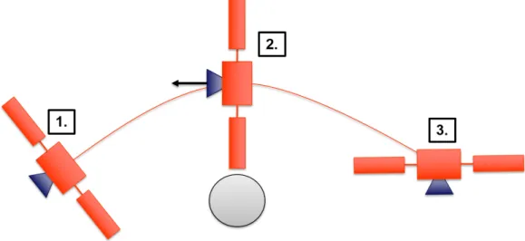
Figure 2-1 provides the reader with a visualization of the “Turn-to-Burn” maneuver.
Figure 2-1: “Turn-to-Burn” Maneuver Visualization
2.4
Case Study 1: Translation
The PPE has a well-defined need to perform translation maneuvers following and preceding the attitude adjustment maneuvers provided in the “Turn-to-Burn” con-trol sequence. In Case Study 1, the PPE is commanded to translate forward in its one-dimensional simulation space by 1.5 meters. This simulation is done using the translational LTI simulation model developed in Chapter 3. The following list details the number of simulation runs that each CSI mitigation strategy will be subjected to, with a note presented on the specific actuators that accompany each of the runs:
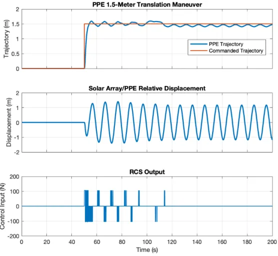
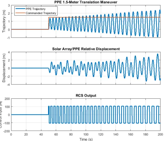
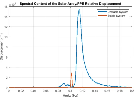
1. Phase Plane: The phase plane CSI mitigation strategy has two simulation runs allocated using the binary “on-off” RCS propulsive jets: one with the notch filters and one without them on the feedback channels. This will allow the reader to see the value of the notch filter approach in removing potentially load-inducing or destabilizing frequencies on the feedback channel of the control architecture which became an important addition to the Space Shuttle’s On-Orbit DAP in the 1990s (expanded upon in Section 4.1).
2. PID: The PID CSI mitigation strategy has one simulation run allocated using the semi-continuous SEP propulsive system. This will require the continuous to semi-continuous limiting function developed for Case Study #1, as discussed in Section 2.2.
3. LQR: The LQR CSI mitigation strategy has three allocated simulation runs us-ing the semi-continuous SEP propulsive system. This will require the continuous to semi-continuous limiting function developed for Case Study #1, as discussed in Section 2.2. The first simulation run will introduce the reader to the fun-damental capabilities of the LQR by manipulating the cost weighting matrices present in the cost function. The second simulation run is dedicated to evaluat-ing the PPE’s performance in an LQR cost function configuration emphasizevaluat-ing the primary 1.5-meter translation control objective. The third simulation run demonstrates the performance limitations of the semi-continuous limiting func-tion by allowing the continuously-variable LQR control input to feed directly into the plant model.
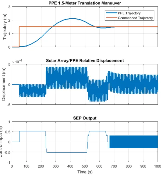
4. FWLQR: The FWLQR CSI mitigation strategy has two allocated simulation runs using the semi-continuous SEP propulsive system. The first simulation run will provide an example of a simulation result without frequency weighting, and the second simulation run will use the same cost weighting matrix setup with the frequency penalization option “on.”
5. MPC: The MPC CSI mitigation strategy has six allocated simulation runs using a combination of one or both the SEP system and/or the RCS. The first, third, and fourth simulation runs consider both the semi-continuous SEP system and the binary RCS system, while the second, fifth, and sixth renditions con-sider the experimental continuous RCS ΔV input variable. Together, these six simulation runs demonstrate the MPC controller’s ability to consider multiple actuation inputs of varying data types with constraints, frequency weighting, and the ability to enforce output constraints.
The number of simulation runs allocated to each CSI mitigation strategy for Case Study #1, in combination with the type of actuator(s) used, is included in Table 2.1.
CSI Mitigation Strategy Simulation Run Number Actuator(s) Used Phase Plane 1 RCS 2 RCS PID 1 SEP LQR 1 SEP 2 SEP 3 SEP FWLQR 1 SEP 2 SEP MPC 1 SEP, RCS 2 ΔV RCS 3 SEP, RCS 4 SEP, RCS 5 ΔV RCS 6 ΔV RCS
Table 2.1: Case Study #1 Simulation Breakdown
2.5
Case Study 2: Attitude Control
In addition to the well-defined need to conduct translation maneuvers, the PPE will be expected to perform routine attitude change maneuvers. In Case Study 2, the PPE is commanded to rotate by 180° in one-dimensional space. This simulation is done using the rotational LTI simulation model developed in Chapter 3. The following list details the number of simulation runs that each CSI mitigation strategy will be subjected to, with a note presented on the specific actuators that accompany each of the runs.
1. Phase Plane: The phase plane CSI mitigation strategy for the rotational model, exactly like the one for the translational model, has two simulation runs allocated using the binary “on-off” RCS propulsive jets: one with the notch filters and one without them on the feedback channel. This will allow the reader to see the value of the notch filter approach in removing potentially load-inducing or destabilizing frequencies.