HAL Id: hal-01683643
https://hal.archives-ouvertes.fr/hal-01683643
Submitted on 23 May 2019
HAL is a multi-disciplinary open access
archive for the deposit and dissemination of
sci-entific research documents, whether they are
pub-lished or not. The documents may come from
teaching and research institutions in France or
abroad, or from public or private research centers.
L’archive ouverte pluridisciplinaire HAL, est
destinée au dépôt et à la diffusion de documents
scientifiques de niveau recherche, publiés ou non,
émanant des établissements d’enseignement et de
recherche français ou étrangers, des laboratoires
publics ou privés.
Tuning the Granular Contribution to Exchange Bias by
Varying the Antiferromagnetic Material but Without
Affecting the Ferromagnetic/Antiferromagnetic Interface
L. Frangou, K. Akmaldinov, C. Ducruet, I. Joumard, B. Dieny, Vincent Baltz
To cite this version:
L. Frangou, K. Akmaldinov, C. Ducruet, I. Joumard, B. Dieny, et al.. Tuning the Granular
Con-tribution to Exchange Bias by Varying the Antiferromagnetic Material but Without Affecting the
Ferromagnetic/Antiferromagnetic Interface. 20th International Conference on Magnetism ICM, 2015,
Barcelona, Spain. pp.1058-1065, �10.1016/j.phpro.2015.12.175�. �hal-01683643�
Tuning the granular contribution to exchange bias by
varying the antiferromagnetic material but without
affecting the ferromagnetic/antiferromagnetic interface
L. Frangou
1,2,3, K. Akmaldinov
1,2,3,4, C. Ducruet
4, I. Joumard
1,2,3, B.
Dieny
1,2,3and V. Baltz
1,2,31
Univ. Grenoble Alpes, SPINTEC, F-38000 Grenoble, France
2
CNRS, SPINTEC, F-38000 Grenoble, France
3
CEA, INAC-SPINTEC, F-38000 Grenoble, France
4
CROCUS Technology, F-38000 Grenoble, France [email protected], [email protected]
Abstract
The exchange bias properties of ferromagnetic/antiferromagnetic (F/AF) bilayers depend strongly on both the F and AF bulk properties, and the interfacial uncompensated AF spins that magnetically couple the F and the AF materials. Whether it is possible to adjust the bulk properties of the AF layer by changing the nature of the AF material but without affecting the interface is one of the challenges raised by the development of some spintronic devices. In this context, we engineered composite AF materials whose basic composition is: (FeMn/Pt/AF). These structures are made of FeMn and IrMn alloys with the insertion of a thin Pt diffusion/trap barrier to Mn in order to ensure as much as possible the integrity of the AF layer at the interface. Magnetic measurements evidenced that, by changing the nature of the AF material, it remains possible to tune the thermal stability of the AF grains without affecting much the interface.
Keywords: TA-MRAM, exchange bias, interface, volume, blocking temperature distribution
1 Introduction
Exchange bias, results from the magnetic exchange interactions between ferromagnetic (F) and antiferromagnetic (AF) materials [1], [2]. Besides the influence of the bulk properties like magnetic anisotropies [3], exchange stiffnesses [1], and grain volumes for polycrystalline films [4], exchange bias effects are also highly dependent on the uncompensated AF spins at the F/AF interface [5]. For a given F/AF bilayer, the uncompensated AF spins can be split into two groups depending on the AF entity to which they belong [6]–[9]: stable grains or interfacial disordered magnetic phases with
low-Volume 75, 2015, Pages 1058–1065
20th International Conference on Magnetism
freezing spins. In thermally-assisted magnetic random access memories (TA-MRAM) [10], the random spread over the sheet film of the disordered magnetic phases contributes to the cell to cell variability of the exchange bias properties once the sheet film is processed into a functional chip [11]. Preserving the integrity of the F/AF interface is therefore part of the challenge for TA-MRAM applications. In addition, minimizing the write power consumption and insuring proper data retention are other parts of the challenge. Besides preserving the F/AF interface, one of the present issues is therefore to find an AF layer with a critical temperature larger than FeMn for better stability but lower than IrMn to reduce power consumption. Simply laminating FeMn and IrMn layers is not sufficient since it provides intermediate properties between FeMn and IrMn for both the bulk and the interface [12]. Actually, data retention relates to the blocking temperature, TB, of the F/AF bilayer. The TB is the
temperature above which the magnetization of the F layer is no longer pinned in a fixed direction by the AF material. By way of contrast, the write power consumption is mostly linked to the Néel temperature, TN, of the AF layer. We recall that the principle to write a TA-MRAM cell relies on field
cooling, i.e. heating and then cooling in a magnetic field, from above the TB [10]. For short heating
pulse widths of few nanoseconds, the TB tends toward the TN. Adjusting the TB does not necessarily
require changing the nature of the AF material since it can be achieved by varying the thickness of the AF layer, for example [4]. More about the physical difference between the TB and the TN can be found
in [1] and [2], for example. In this case the F/AF interface can be preserved straightforwardly. However, tuning simultaneously the TB and the TN does necessitate a change in the nature of the AF
material. In fact, although the TB depends on both intrinsic (e.g. the AF anisotropy) and extrinsic (e.g.
the volume of the AF grains and the exchange stiffness between F and AF moments) properties, the TN
is mostly driven by the exchange stiffness between the AF moments, which is an intrinsic property of the AF material. In the present study, we engineered composite AF materials in order to evidence whether it is possible to vary the nature of the AF material without affecting much the F/AF interface.
2 Method
The specimens are deposited on thermally oxidized silicon substrates, Si/SiO2, using a magnetron
sputtering machine with an argon plasma. The machine base pressure is 4x10⁻⁷ mbar and the argon pressure during deposition is set to 3.5x10⁻³ mbar. The following multilayers are studied: Si/SiO2//Ta3/Cu3/Co3/AF/Pt2(nm). Note that the thicknesses of the layers are given as subindexes. A
tantalum/copper bilayer, Ta3/Cu3, is used as buffer and a cap of 2 nm of platinum, Pt2, prevents
oxidation of the specimens. The active magnetic stacks consist of different AF structures coupled to the same F material: here, 3 nm of cobalt: Co3. The AF structures are either single layers used as
references: iron(50 at.%)-manganese(50 at.%), FeMn, and iridium(20 at.%)-manganese(80 at.%), IrMn, or more complex composite multilayers. The AF structures are split in two groups, whether FeMn or IrMn bonds with Co at the F/AF interface: AF = FeMn10, FeMn2/Pt0.4/(IrMn1/FeMn1)x4, and
FeMn2/Pt0.4/IrMn8; and AF = IrMn10, IrMn2/Pt0.4/(IrMn1/FeMn1)x4, and IrMn2/Pt0.4/FeMn8. The overall
thickness of the AF layer is kept constant at 10 nm. In the absence of a diffusion barrier to Mn, IrMn/FeMn interfaces mix. Thus, the (IrMn1/FeMn1)x4 multilayer resembles more an IrFeMn alloy
[12]. This is actually similar to CoO and NiO mixing that were earlier used to tune the AF properties between those of CoO and NiO [13]. To preserve the integrity of the AF layer at the interface with the F, we inserted a Pt spacer that acts as a diffusion barrier/getter to Mn [14], [15]. It is however thin enough: 0.4 nm to ensure magnetic coupling between the AF layers situated on both sides. We remark that the AF structures are grown on top of the F layer. In this way, the F/AF interface does not depend on the growth variability between the various AF structures. Basically, we engineered a first series of samples with an attempted constant Co/FeMn interface coupled to FeMn, IrFeMn and IrMn bulks and a second series with an expected constant Co/IrMn interface coupled to the same AF bulk.
Tuning the granular contribution to exchange bias ... L. Frangou et al.
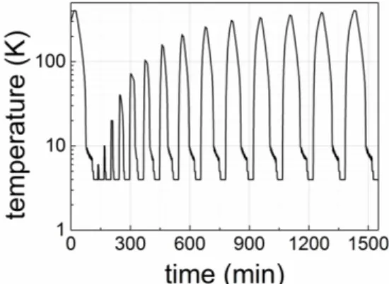
Following deposition, we quantified the magnetic quality of the F/AF interface and the thermal stability of the AF bulk by means of blocking temperature distribution measurements [7], [16]. To do so, initial exchange bias is first set via post-deposition field cooling (FC) with a positive field, from 573 down to 4K. This step orients all the AF entities toward the positive direction, since, for all the samples, 573K is above the maximum blocking temperature. Actually, due to the temperature range limitations of our vibrating sample magnetometer (VSM), the initial FC is done in two stages: FC in a furnace from 573K for 60 min down to room temperature and hysteresis loop measurements at 300K in the insert of a VSM, and then FC in the insert of the VSM from 400 to 4K. From this initial state, standard negative FC from incremental annealing temperatures, Ta, down to 4K gradually reverses the
AF entities toward the negative direction (Fig. 1). Hysteresis loop measurements at 4K after each increment of Ta records the progressive reorientation of the AF entities. Details of this standard
procedure by Soeya et al and later simply extrapolated to low-enough temperatures for the complete quantification of the F/AF interfacial properties can be found in Refs. [7] and [16], for example. During the hysteresis loop (Fig. 2), the magnetic field is swept between plus and minus 5 kOe with a rate of 10 Oe/s. Due to thermal activation, it is known that the magnetization reversal shows a logarithmic dependence with the sweep rate. For NiFeCo/FeMn samples, at room temperature, earlier studies found a 10% change in the reversal field for sweep rates ranging from 0.01 to 1 Oe/s [17]. Although the magnetization reversal is inevitably linked to the sweep field rate, we recall that the hysteresis loops are measured here at 4K, i.e. for a thermal activation energy of 0.33 meV. The temperature sweep rates during the heating and cooling process can be deduced from Fig. 1. Due to the limitations of our setup and subsequent changes in the heating/cooling regimes, we have a rate of around 5 K/min from 400 to 70K, 10 K/min from 70 to 10K, 0.3 K/min from 10 to 7K and again 10 K/min from 7 to 4K. Thermal activation is an important parameter to consider in exchange bias experiments. In particular, setting the AF in a reproducible manner is key to data interpretation [9], [18]. Here, at every step of the procedure, we observed no training effects, meaning that sufficient time was let to the system to relax and henceforth to reach a stable minimum of energy. In addition, we remark that the data are reproducible. Finally, we note that the value of HC measured at 4K, does
not depend on Ta (Fig. 2). This is an additional indication of the absence of training effects, as for
example detailed in [18].
Figure 1. Dependence of the temperature with time, during the measurement procedure. Initial positive field cooling with 1T down to 4K is followed by negative field cooling with -1T from various incremental temperatures down to 4K. Hysteresis loops are systematically measured at 4K.
3 Results and Discussion
Representative hysteresis loops measured at 4K after various steps of the measurement procedure are depicted in Fig. 2. The usual change in the amplitude and sign of hysteresis loop shift accounts for
the gradual reorientation of the AF entities [7]. This is better visible in Fig. 3, where we plotted the variations with Ta of the normalized hysteresis loop shifts, HE / |HE (Ta = 4K)|. Actually, for every increment of Ta, HE integrates the AF entities still oriented positively (with TB larger than Ta and
unaffected by the negative FC from Ta down to 4K) minus those reoriented negatively (with TB lower
than Ta) [7], [16]. Therefore, the plot of HE / |HE (Ta = 4K)| vs Ta (Fig. 2) relates to the integral of the TB distribution. As a result, a peak in the distribution reads as an inflection point in the HE / |HE (Ta = 4K)| vs Ta plot and the surface of the corresponding peak is equal to the amplitude around the inflection point. The position of the peak (inflection point) is an indication of the thermal stability of the corresponding AF entities and the surface (amplitude around the inflection point) is proportional to the amount of AF entities. Since we can extract the same information from either the blocking temperature distribution or its integral (HE / |HE (Ta = 4K)| vs Ta) and because it is more accurate to work on the raw HE / |HE (Ta = 4K)| vs Ta data rather than adding a data derivation step, we will work on the HE / |HE (Ta = 4K)| vs Ta data.
Figure 2. (color online) Representative hysteresis loops measured along the field cooling direction by VSM at 4K,
for a Si/SiO2//Ta3/Cu3/Co3/FeMn10/Pt2(nm) film. The measurements follow the procedure described in the text.
Such a procedure involves negative field cooling from various annealing temperatures (Ta) down to 4K, in order
to progressively reorient the AF entities.
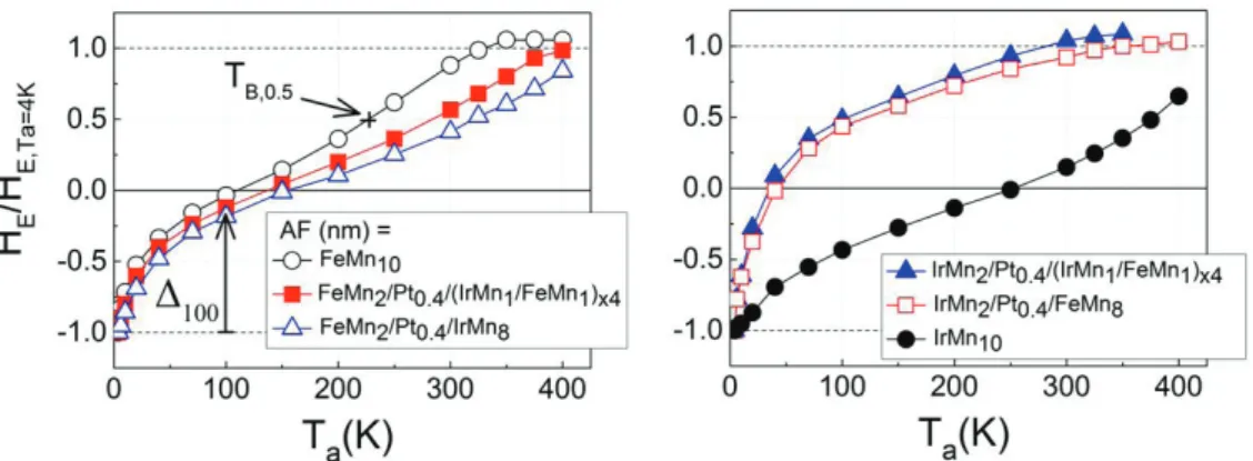
Figure 3. (color online) For Si/SiO2//Ta3/Cu3/Co3/AF/Pt2(nm) multilayers with various composite AF materials,
dependence of the normalized exchange bias loop shift measured at 4K (HE/HE, Ta=4K) on the annealing
temperature (Ta). We recall that, in order to progressively reorient the AF entities, the procedure described in the
text involves negative field cooling from incremental Ta down to 4K. The data are split in two, whether the
composite AF material has FeMn (top) or IrMn (bottom) at the interface with the F material, here Co. Within each
set of data, the F/AF interface is kept the same while the bulk of the composite AF is varied. Δ100 and TB,0.5 are
indicated in the top graph. They are used to compare the disordered magnetic phases at the F/AF interface and the thermal stability of the AF grains, respectively.
Tuning the granular contribution to exchange bias ... L. Frangou et al.
In the left panel of Fig. 3, one distinguishes two inflections in the HE / |HE (Ta = 4K)| vs Ta
dependences. These two inflections are usual and account for the acknowledged two contributions to the TB distribution [7], [8]. The two contributions seem to slightly overlap here since the two
inflections are not clearly separated by a plateau. It is known that the AF grain volume distribution gives rise to the high-temperature contribution to the TB distribution [4]. It is also recognized that the
low-temperature contribution is due to interfacial disordered magnetic phases [6]. As indicated in Fig. 2, Δ100 is the difference between HE after Ta = 4 and 100K. In the following, we will extract the values
of Δ100 to compare the interfacial disordered magnetic phases between the various structures. To ease
the interpretation, such a comparison usually uses normalized data [7], [8]: Δ100 *
equals Δ100
normalized to the total expected variations of HE, i.e. 2 for normalized HE: from -1 (when all the AF
entities contributing to HE at 4K are initially oriented positively) to 1 (when all the entities are
reoriented negatively after completion of the FC procedure). We recall that when all the AF entities are reoriented, when Ta is equal to the maximum TB, HE reaches again its maximum amplitude but
with opposite sign compared to the initial value of HE and it then levels out. Here, we observe in Fig. 3
that the maximum TB could not be reached for all samples during the measurement procedure
(although we remind that the initial FC was partly done ex-situ in an external furnace from above the maximum TB). Given that, instead of using the maximum TB, we selected TB,0.5 (indicated in Fig. 3) in
order to compare the thermal stability of the AF grains between the various samples.
Before discussing the variations with the AF structures of the disordered magnetic phases at the interface and of the thermal stability of the AF grains, we will separately comment on the specific case of the Si/SiO2//Ta3/Cu3/Co3/AF/Pt2(nm) samples with AF = IrMn2/Pt0.4/(IrMn1/FeMn1)x4, and
IrMn2/Pt0.4/FeMn8. In fact, Fig. 3(right), tells us that, for these two samples compositions, the high-
and low-temperature contributions entirely overlap. In such cases, Δ100 no more accounts mostly for
the low-temperature contribution and is of no physical meaning. The overlap seems to be due to a shift of the high-temperature contribution toward low blocking temperatures. It means that the AF grains are very unstable against thermal activation. This lack of thermal stability could be attributed to a poor structural quality of the IrMn2/Pt0.4/(IrMn1/FeMn1)x4, and IrMn2/Pt0.4/FeMn8 multilayers grown on top
of Co. Attempts to prove so quantitatively with the determination of the expected fcc (111) texture of the layers [19] by X-ray diffractions were unsuccessful. Actually, due to the complexity of the multilayers, the subsequent overlap of the specular diffraction peaks precluded any relevant rocking curve measurement.
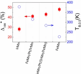
When relevant, the values accounting for the contribution of the interfacial disordered magnetic phases: Δ100
*
and the thermal stability of the AF grains: TB,0.5 are plotted in Fig. 4 for the various
Co/AF structures. While the thermal stability of the AF grains, TB,0.5, evolves gradually from sample
to sample, the contribution of the interfacial disordered magnetic phases, Δ100*, seems to show distinct
behaviours whether a Co/IrMn interface is involved, for AF = IrMn10, or a Co/FeMn is used for AF =
FeMn2/Pt0.4/IrMn8, FeMn2/Pt0.4/(IrMn1/FeMn1)x4, and FeMn10. We remark that
FeMn2/Pt0.4/(IrMn1/FeMn1)x4 can also be written FeMn2/Pt0.4/IrFeMn8 since IrMn/FeMn are known to
resemble more IrFeMn alloys with intermediate properties between IrMn and FeMn [12]. For consistency, FeMn10 will also be written FeMn2/FeMn8. Note that the maximum TB trend (by
extrapolating HE vs Ta to 1 in Fig. 3) is the same as TB,0.5, which further justifies the use of TB,0.5. For a
constant F/AF interface and the various AF bulks, the differences in the thermal stability of the AF grains between the various AF bulks mostly relates to the differences in the AF volume times magnetic anisotropy product [7], [9]. As a first approximation, this explains the variation of TB,0.5. An
IrMn8 bulk shows grains with smaller volumes compared to a thicker IrMn10 layer. First, from
previous literature [9], it is known that the grains’ diameter may increase when increasing the thickness of the layer. We do not exclude so, here. Second, earlier x-ray diffraction measurements for similar samples confirmed that, in this range of thicknesses, the vertical coherence length of the structure of the grains is equal to the IrMn thickness. This was obtained by fitting the full width at half maximum of the IrMn (111) specular peak with the Scherrer formula. Given that, increasing the
thickness of the layer also increases the volume of the grains. In addition, it is known that FeMn grains are less stable than IrMn grains, likely due to a smaller anisotropy. Finally, it is also known that the grains in laminated IrMn/FeMn layers show intermediate thermal stabilities between IrMn and FeMn grains [12]. Here however, this simple picture is probably more complex. Although the samples with AF = FeMn2/Pt0.4/IrMn8, FeMn2/Pt0.4/IrFeMn8, and FeMn2/FeMn8 have the same Co/FeMn interface,
the respective coupling to the FeMn2 interface of the IrMn8 and IrFeMn8 bulks are done across a thin
Pt layer of 0.4 nm for the first two compositions in contrast to the last composition where the FeMn8
bulk directly couples to the FeMn2 interface. This may also explain the fact that the values of Δ100* for
these three samples are not strictly the same. Note that coupling between the AF bulk and the interface is essential and therefore that the value of the Pt spacer thickness is important. In particular, as shown in Fig. 5, for a too thick Pt spacer of 1 nm, the high- and low-temperature contributions entirely overlap. In fact, the thick Pt spacer hinders the interaction between the AF bulk and the interface. As a result, the exchange biasing is only controlled by the interaction between the Co and the interfacial AF: FeMn2. Given its reduced thickness, a sole FeMn2 cannot sustain large blocking temperatures [1]
and the high-temperature contribution shrinks toward low-temperatures.
Figure 4. (color online) Comparison of the contribution of the disordered magnetic phases at the F/AF interface (Δ100* = Δ100/2) and of the thermal stability of the AF grains (TB,0.5), for Si/SiO2//Ta3/Cu3/Co3/AF/Pt2(nm) multilayers with various composite AF materials: AF (nm) = IrMn10, FeMn2/Pt0.4/IrMn8, FeMn2/Pt0.4/(IrMn1/FeMn1)x4 and FeMn10.
Figure 5. (color online) Dependence of the normalized exchange bias loop shift measured at 4K (HE/HE, Ta=4K) on the annealing temperature (Ta) for Si/SiO2//Ta3/Cu3/Co3/AF/Pt2(nm) multilayers with AF = IrMn2/PttPt/(IrMn1/FeMn1)x4, and tPt = 0.4 and 1 nm.
Tuning the granular contribution to exchange bias ... L. Frangou et al.
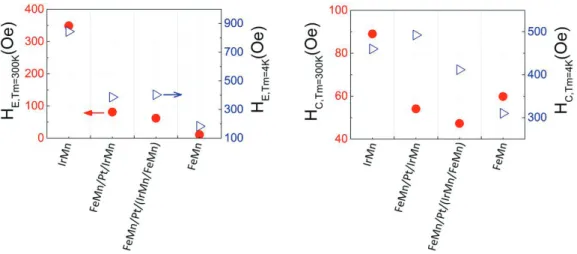
Figure 6 shows the hysteresis loop shift, HE, and the coercive field, HC, measured at 4 and 300K for the various Co/AF structures. Although HE seems to follow distinct behaviors whether Co is in contact with IrMn or FeMn at the interface, the values of HE and HC do not only depend on the interface. In fact, many materials parameters impact on HE and HC: interface-related parameters such as the F/AF interfacial exchange stiffness and the amplitude of the AF moments; to which adds the amount of AF entities remaining fixed during the magnetization reversal of the F layer and that relate to both the interface, the AF bulk and the connection between the two. In addition, those parameters depend on temperature. For a measurement at 300K, the case is complex since only part of the
distribution is integrated. Only the AF grains with TB larger than 300K remain fixed. In contrast, for
4K, the AF entities: interfacial disordered magnetic phases and AF grains are fixed since all the distribution is integrated (only the few and smallest interfacial disordered magnetic phases with TB smaller than 4K do not contribute to HE).
Figure 6. (color online) (Left) exchange bias and (Right) coercive fields measured at Tm= 4 and 300 K for
Si/SiO2//Ta3/Cu3/Co3/AF/Pt2(nm) multilayers with various composite AF materials: AF (nm) = IrMn10,
FeMn2/Pt0.4/IrMn8, FeMn2/Pt0.4/(IrMn1/FeMn1)x4 and FeMn10.
4 Summary
In conclusion, by changing the nature of the AF material in F/AF bilayers, we showed that it is possible to mainly tune the AF volume contribution to exchange bias without affecting much the F/AF interface. To achieve so, we engineered composite AF materials based on FeMn and IrMn alloys with the insertion of a thin Pt diffusion/trap barrier to Mn in order to preserve as much as possible the integrity of the AF layer at the interface. Although materials engineering is still needed to match all the requirements for applications, our results mean that it is a priori possible to find AF materials with various intrinsic properties such as TN (i.e. at a TA-MRAM level with various write power) without affecting the F/AF interface (i.e. without affecting the cell to cell variability of the exchange bias properties in MRAM chips).
References
[1] J. Nogués and I. K. Schuller, “Exchange bias,” J. Magn. Magn. Mater. 192, 203, 1999.
[2] A. E. Berkowitz and K. Takano, “Exchange anisotropy-a review,” J. Magn. Magn. Mater. 200, 552, 1999.
[3] E. Jiménez, J. Camarero, J. Sort, J. Nogués et al, “Emergence of noncollinear anisotropies from interfacial magnetic frustration in exchange-bias systems,” Phys. Rev. B 80, 014415, 2009.
[4] E. Fulcomer and S. H. Charap, “Thermal fluctuation aftereffect model for some systems with ferromagnetic-antiferromagnetic coupling,” J. Appl. Phys. 43, 4190, 1972.
[5] H. Ohldag, A. Scholl, F. Nolting, E. Arenholz et al, “Correlation between Exchange Bias and Pinned Interfacial Spins,” Phys. Rev. Lett. 91, 017203, 2003.
[6] K. Takano, R. H. Kodama, A. E. Berkowitz, W. Cao et al, “Interfacial Uncompensated Antiferromagnetic Spins: Role in Unidirectional Anisotropy in Polycrystalline Ni81Fe19/CoO Bilayers,” Phys. Rev. Lett. 79, 1130, 1997.
[7] V. Baltz, B. Rodmacq, A. Zarefy, L. Lechevallier et al, “Bimodal distribution of blocking temperature in exchange-biased ferromagnetic/antiferromagnetic bilayers,” Phys. Rev. B 81, 052404, 2010.
[8] G. Lhoutellier, D. Ledue, R. Patte, F. Barbe et al, “Bimodal distribution of blocking temperature for exchange-bias ferromagnetic/antiferromagnetic bilayers: a granular Monte Carlo study with less stable magnetic regions spread over the interface,” J. Phys. D. Appl. Phys. 48, 115001, 2015.
[9] K. O’Grady, L. E. Fernández-Outón, and G. Vallejo-Fernandez, “A new paradigm for exchange bias in polycrystalline thin films,” J. Magn. Magn. Mater. 322, 883, 2010.
[10] I. L. Prejbeanu, S. Bandiera, J. Alvarez-Hérault, R. C. Sousa et al, “Thermally assisted MRAMs: ultimate scalability and logic functionalities,” J. Phys. D. Appl. Phys. 46, 074002, 2013.
[11] K. Akmaldinov, L. Frangou, C. Ducruet, C. Portemont et al, “ Correlation between disordered magnetic phases above ferromagnetic/antiferromagnetic thin films and device-to-device variability of exchange bias in spintronic applications,” IEEE Mag. Lett. in press, 2015.
[12] K. Akmaldinov, C. Ducruet, C. Portemont, I. Joumard et al, “Mixing antiferromagnets to tune NiFe-[IrMn/FeMn] interfacial spin-glasses , grains thermal stability and related exchange bias properties,” J. Appl. Phys. 115, 17B718, 2014.
[13] M. J. Carey, A. E. Berkowitz, J. A. Borchers, and R. W. Erwin, “Strong interlayer coupling in CoO/NiO antiferromagnetic superlattices,” Phys. Rev. B, 47, 9952, 1993.
[14] L. Lechevallier, A. Zarefy, R. Lardé, H. Chiron, et al, “Structural analysis and magnetic properties of (Pt/Co)3/PttPt/IrMn multilayers,” Phys. Rev. B 79, 174434, 2009.
[15] F. Letellier, L. Lechevallier, R. Lardé, J.-M. Le Breton, et al, “Direct imaging of thermally-activated grain-boundary diffusion in Cu/Co/IrMn/Pt exchange-bias structures using atom-probe tomography,” J. Appl. Phys. 116, 203906, 2014.
[16] S. Soeya, T. Imagawa, K. Mitsuoka, and S. Narishige, “Distribution of blocking temperature in bilayered Ni81Fe19/NiO films,” J. Appl. Phys. 76, 5356, 1994.
[17] A. M. Goodman, K. O’Grady, H. Laidler, N. W. Owen, et al, “Magnetization reversal processes in exchange-biased spin-valve structures,” IEEE Trans. Mag. 37, 565, 2001.
[18] V. Baltz, “Thermally driven asymmetric responses of grains versus spin-glass related distributions of blocking temperature in exchange biased Co/IrMn bilayers,” Appl. Phys. Lett. 102, 062410, 2013.
[19] M. Fecioru-Morariu, G. Güntherodt, M. Rührig, A. Lamperti et al, “Exchange coupling between an amorphous ferromagnet and a crystalline antiferromagnet,” J. Appl. Phys. 102, 053911, 2007.
Tuning the granular contribution to exchange bias ... L. Frangou et al.