HAL Id: hal-01632431
https://hal.inria.fr/hal-01632431v2
Preprint submitted on 19 Feb 2018HAL is a multi-disciplinary open access
archive for the deposit and dissemination of sci-entific research documents, whether they are pub-lished or not. The documents may come from teaching and research institutions in France or abroad, or from public or private research centers.
L’archive ouverte pluridisciplinaire HAL, est destinée au dépôt et à la diffusion de documents scientifiques de niveau recherche, publiés ou non, émanant des établissements d’enseignement et de recherche français ou étrangers, des laboratoires publics ou privés.
P4Bricks: Enabling multiprocessing using Linker-based
network data plane architecture
Hardik Soni, Thierry Turletti, Walid Dabbous
To cite this version:
Hardik Soni, Thierry Turletti, Walid Dabbous. P4Bricks: Enabling multiprocessing using Linker-based network data plane architecture. 2018. �hal-01632431v2�
P4Bricks: Enabling multiprocessing using Linker-based
network data plane architecture
Hardik Soni, Thierry Turletti, Walid Dabbous
Abstract
Packet-level programming languages such as P4 usually require to describe all packet processing functionalities for a given programmable network device within a single program. However, this approach monopolizes the device by a single large network application program, which prevents possible addition of new functionalities by other independently written network applications.
We propose P4Bricks, a system which aims to deploy and execute multiple independently developed and compiled P4 programs on the same reconfigurable hardware device. P4Bricks is based on a Linker component that merges the pro-grammable parsers/deparsers and restructures the logical pipeline of P4 programs by refactoring, decomposing and scheduling the pipelines’ tables. It merges P4 pro-grams according to packet processing semantics (parallel or sequential) specified by the network operator and runs the programs on the stages of the same hardware pipeline, thereby enabling multiprocessing. This paper presents the initial design of our system with an ongoing implementation and studies P4 language’s fundamental constructs facilitating merging of independently written programs.
1
Introduction
P4 [1] is a high-level language for programming protocol-independent packet proces-sors. It allows reconfiguring packet processing behavior of already deployed data plane hardware devices, introducing new protocols and their processing to the devices, hence decoupling packet processing hardware from software. This provides high degree of flex-ibility for programming new network applications and packet processing functionalities using reconfigurable hardware like RMT [2] and Intel FlexpipeTM. With P4, a network operator can execute one program at a time on the target reconfigurable network de-vice. However, as the number of features or network applications to be supported by the device grows, P4 programs increase in complexity and size. The development and maintenance of such monolithic P4 programs containing all the possible features is er-ror prone and needs huge time and effort as program complexity grows. On the other hand, this approach does not allow to easily compose independently written modules in a single P4 program. Network devices can have different packet processing requirements according to their role and location in the network. Deploying one large program for a small subset of applications results in inefficient utilization of the reconfigurable device resources.
P5 [3] optimizes resource utilization by leveraging policy intents specifying which fea-tures are required to remove excess applications and packet processing functionalities. However, with P5 there is still a large monolithic program to be configured based on
P4Bricks 1. Introduction
the policy intents. ClickP4 [4] proposes a smart modular approach in which separate modules can be developed within the ClickP4 programming framework and then man-ually integrated into ClickP4 configuration files to create a large program. However, programmers are required to know the code of the ClickP4 library modules to integrate a new module into the ClickP4 framework as source code modifications may be required for modules on the already developed code base. Basically, P5 allows removing extra modules and features from already composed small P4 programs, whereas ClickP4 gives choice to select from a list of modules. Most importantly, with both P5 and ClickP4, packet processing functionalities on a device can not be easily composed using indepen-dently developed and compiled P4 programs.
Hyper4 [5], HyperV [6] and MPVisor [7] propose virtualization of programmable data plane in order to deploy and run independently developed multiple P4 programs on the same network device at the same time. In these approaches, a general purpose P4 program working as a hypervisor for programmable data plane is developed, which can be configured to achieve functionally equivalent packet processing behavior of multiple P4 programs hosted by it. However, virtualization requires minimum 6-7× and 3-5× more match-action stages for every P4 program compared to its native execution for Hyper4 and HyperV, respectively. Also, such approaches show significant performance degradation for bandwidth and delay, thereby nullifying the benefit of high performance reconfigurable hardware.
Meanwhile, executing efficiently multiple P4 programs at a time on a same target device is highly desirable. We believe that a network operator should be able to easily add any features on its target device with programs potentially developed by different providers. We present the design and architecture of P4Bricks, our under development system that aims to deploy and execute multiple independently developed and compiled P4 programs on the same reconfigurable device. P4Bricks comprises two components, called Linker and Runtime. The Linker component merges the programmable parsers and deparsers and restructures the logical pipeline of P4 programs by refactoring, decomposing and scheduling their match-action tables (MATs). The Runtime component translates the dynamic table updates from the control planes of different applications into the tables of the merged pipeline. P4Bricks merges and executes MATs of multiple compiled P4 programs on the stages of the same hardware pipeline, thereby enabling multiprocessing. The idea is to provide a seamless execution environment for P4 programs in a multi-program environment without any changes required in its control interface and MATs definitions. With P4Bricks network operators can specify the packet processing policy on the target device in terms of compiled P4 programs and composition operators using a simple command line interface.
This report presents the initial design of our system with an ongoing implementation and studies P4 language’s fundamental constructs facilitating merging of independently written programs. It is organized as follows. Section 2 provides an overview of the P4Bricks system. Section 3 describes Linker, which composes compiled P4 programs using the only knowledge of MATs definitions. Then, Section 4 describes the Runtime module that interacts with the Linker component and the control plane of P4 programs to manage flow entries in the MATs of the programs.
P4Bricks 2. System Overview
2
System Overview
In this section, we provide a brief overview of the P4 language and we then introduce our system, describing merging of programmable blocks at link time and their management at runtime.
2.1 P4 background
P4 [1] is a high-level language, based on programmable blocks, used to define protocol-independent packet processing by programming data plane of reconfigurable target de-vices. A P4-compatible target manufacturer provides P4 architecture defining the pro-grammable blocks and describing several hardware related information. Essentially, the P4 architecture of a target provides programmable components and declares inter-face to program them and exposes specific and already implemented constructs(e.g., checksum units and algorithms) that can be used and manipulated through APIs. The programmable parser, deparser and logical match-action pipeline are the main blocks used to program the data plane of packet processing targets. In addition of providing data plane programmability, P4 generates the APIs for control plane of the target device to communicate with the data plane. The APIs allow to manage the state of data plane objects from the control plane.
P4 provides the following fundamental abstractions to program reconfigurable target devices.
• Header types - to describe the format (ordered sequence of fields and their size) of headers within a packet.
• Parser - to describe all the possible sequences of headers within received packets, mechanism to identify the header sequences, headers and the values of the fields. • Actions - are already implemented in the target, hence their behaviors are fixed.
They are used manipulate header fields and metadata, also may take data as input from control plane at runtime.
• Tables - allows P4 programmer to define match keys and associate them with actions. A Match key can have multiple header and metadata fields. A Match key provides complex match and decision capabilities.
• Match-action unit - implements a table for execution at runtime. It performs table lookup using the match key to search associated actions and data, and executes the actions.
• Control Flow - to describe packet processing program, which includes invoking se-quence of Match-action units. Packet reassembly can also be defined using control flow.
• extern - are architecture and hardware specific objects and implementations, which can be manipulated but not programmed. Because, their processing behav-iors are implemented in the target.
• Intrinsic metadata - are architecture and target specific entities associated with each packet(e.g., interfaces)
P4Bricks 2.1 P4 background
• User-defined metadata - are data structures and variables defined in a program to maintain the program specific per packet state during packet processing. The P4 language is constituted of four different sub-languages used for different purposes.
1. The core language - to describe types, variables, scoping, declarations, statements etc.
2. A sub-language for describing parsers - having specific constructs to describe packet parsing.
3. A sub-language for describing processing - using match-action units and to define traditional imperative control flow for packet processing
4. A sub-language for describing architecture - to define and declare types of pro-grammable blocks for the target, architecture specific data and functions.
Next, we briefly discuss sub-languages for parsers and packet processing along with some of their fundamental constructs used to program Parsers, Deparser and logical match-action pipeline.
2.1.1 Programmable Parser and Packet Parsing in P4
All the packet processing targets must identify packets’ protocol headers and their fields to determine how packets can be processed. Identifying and extracting protocol headers and their fields within packets is called packet parsing. Packet parsing is a complex and challenging as the packet size, protocol header types and their payload vary across the networks and packets within the same network. Header type defines the format of a protocol header within a packet, programmers can describe it by specifying sequence of fields and their sizes. Every header type has a length field and an identifier field indicating length of the current header and encapsulated protocol type, respectively, to facilitate extraction of header fields and subsequent protocols headers. The first protocol header fields are extracted based on the network type from the start of packet bit-stream. Parser identifies the next protocol header to extract from the values of current protocol header’s fields using a given parse graph, which captures all possible sequences of protocol headers using a DAG. Fixed parsers can parse packets according to the parser and protocol types defined at design time of the target. Where as programmable parsers allow to modify the parse graph and protocol headers types at any time according to new packet processing requirements.
P4 allows to define programmable parser blocks for P4-compatible reconfigurable tar-get. Parser blocks are programmed by defining packet header types and fields, declaring instances of the types and defining a Finite State Machine (FSM) to extract the header instances from the packets’ bit streams. The parse graph is encoded as FSM in P4. The FSM structure is described by defining states and transitions among the states. The programmer must define one start state for FSM of a P4 parser. P4 provides two logical final states named accept and reject, which are not part of the FSM defined by the programmer. The programmer can define next transition to accept state or reject state from any state of the parser to notify successful completion or failure packet in parsing, respectively. Each state has a name and a body comprising of a sequence of statements. The statements within a state’s body describe the processing to perform when the parser
P4Bricks 2.1 P4 background
transits to the state. They can be local variable declarations, assignments, function in-vocation(e.g., verify - to validate already parsed data) and method calls (to process parsed fields using extract and invoke other parser blocks defined within the same pro-gram). P4-compatible target implements the parser FSM in their programmable parser unit [8], where FSM is converted into state transition table and loaded into the unit’s memory blocks. Packets parsed into header using defined parser blocks instances are further processed using control blocks.
2.1.2 Control Block
P4 provides a specific language constructs to program control block describing processing of the parsed headers and other metadata in the parser block. Actions and tables are among the fundamental packet processing abstractions declared within the body of control block. P4 uses the same control block but with specialized signature as the programming interface deparsing.
2.1.3 Programming match-action units
P4 language construct tables are used to describe packet processing in match-action units of targets. In this thesis, we use Match-Action Tables (MATs) to refer tables declared in P4 programs. Every definition of MAT must have a key (match key), actions and optionally, can have a default action, entries and additional properties. The key specifies data plane entities like header fields, program variables or metadata to be used to match values at runtime in hardware lookup table of a match-action unit. A key is described using a list of (field, match kind ) pairs, where field is a data plane entity and match kind is a constant specifying an algorithm to match the values at runtime in the lookup table of the match-action unit. match kind constants are useful to allocate specific memory type and resources to implement lookup table and generate control plane APIs used to manage entries in the MAT. Actions are code fragments processing data(e.g., header fields, metadata etc.,) in data plane and may additionally contain data that can be written by control plane and read by data plane. Actions used in every MAT must be defined in the P4 program. A MAT must declare all the possible actions which may appear in lookup table at runtime by assigning list of the actions to its actions property. Actions allow control plane to influence packet processing behavior of data plane, dynamically. P4 allows to declare default action for MATs, which can be dynamically changed using control plane APIs. The default actions of a MAT is executed by the corresponding match-action unit, whenever key values do not match any entry in the lookup table. If the definition of a MAT does not have default action property declared and key values do not match any entry in the lookup table, then packet processing continues without any effect from the MAT. P4 allows to initialize look up tables by declaring a set of entries in definitions of MATs. These entries are constant and can not be changed by control plane at runtime, they can be only read. P4 allows to specify target architecture specific properties to pass additional information to compiler back-end of the target (e.g., table size, lookup table implementation hints etc.,).
In control block, programmers can invoke a MAT using its apply method, which is a language construct provided by P4. Call to an apply method on a MAT instance
P4Bricks 2.2 The P4Bricks System P4 Linker MATs Mappings MATs Update Schedules UIDTs for Header Types Instances Runtime MATs’ Context Reconfigurable Target Parser Match+Action Stages Programs.p4 Programs-CP P4 Compiler (e.g., BMV2 target) Intermediate Representations(IRs) (de)Parser Configuration MAT CFG (Programs.json) Composition Operators
Figure 1: System Overview
execute the MAT using match-action unit of the target. The call returns a struct having a boolean and an enum as its fields. The return type struct and its member enum are automatically generated by the P4 compiler. The boolean member specifies if a matching entry is found in the lookup table or not. The enum member indicates the type of action executed as a result the execution. The boolean and enum fields can be used in if and switch construct to program packet processing control in the control block.
2.1.4 Deparser Control Block
Packets are reassembled using the processed header instances by programming the de-parser control block. Deparsing is described using a control block having a mandatory specific parameter of type packet out. P4 provides a language construct, emit, to re-assemble the packet. Emit takes header instance as an argument and if the header instance is valid, it is appended to the packet. If the header is not valid, no operation is performed.
2.2 The P4Bricks System
P4Bricks enables network operators to deploy and execute multiple independently de-veloped and compiled P4 programs on the same reconfigurable target device. P4Bricks allows network operator to define packet processing policy of the device using P4 pro-grams and composition operators. It merges P4 propro-grams according to packet processing semantics (parallel or sequential) specified by the network operator and runs the pro-grams on the stages of the same hardware pipeline, thereby enabling multiprocessing. P4Bricks comprises two components, called Linker and Runtime. Linker takes as input the data plane configuration files generated by P4 compiler from source files of indepen-dently written P4 programs along with composition operators to apply on the programs, see Figure 1. It merges the programmable parser, pipeline and deparser blocks defined in the compiled configuration files of P4 programs according to packet processing policy described using parallel and sequential composition operators. It restructures the logical pipeline of P4 programs by refactoring, decomposing and scheduling their match-action tables (MATs). Linker does not assume knowledge of flow entries in MATs of P4 pro-grams while merging the pipelines at link time. On the other hand, Runtime processes
P4Bricks 2.2 The P4Bricks System
the MATs flow updates from the control plane of P4 programs at runtime, in accordance with composition operators and traffic isolation enforced by the network operator. The Runtime component translates the dynamic table updates from the control planes of different applications into the tables of the merged pipeline.
In order to merge the parsers, Linker has to identify equivalent header types and header instances present in the different P4 programs to enable sharing of common header types and instances. Two packet header types are said equivalent if they have the same format. Linker maps header types to Unique IDentifiers (UIDs) and stores the mappings between program specific IDs and UIDs in a table called header types UID Table (UIDT). Equivalent packet header instances are identified while merging the parse graphs defined in parser block of P4 programs. The parse graphs are merged by matching the sampling locations of parsers in the packet bit stream and the instances of header types extracted from the location. The mapping between program specific IDs and UIDs is also stored in a table called header instances UIDT. As merging parsers of two programs creates another parser, the composition operators can be recursively applied to merge parsers of any number of programs.
P4Bricks considers the packet header instances (extracted or emitted) along with User-defined and Intrinsic metadata associated with each packet as data plane resources. We consider the packet header instances and intrinsic metadata as shared data plane resources accessed for packet processing by the logical pipelines of the different P4 programs. However, we do not share user-defined metadata of one program with the other P4 programs because they are used by programmers to store the program specific state during packet processing. Linker replaces program specific IDs of header types and instances given by the compiler with the mapped ones in UIDTs before merging pipelines according to the composition operators. This unifies different references (IDs and names) for equivalent header types and instances used in P4 programs, thereby iden-tifying sharing of data plane resources. As Intrinsic metadata represents data structures and variable related to architecture and target, they are uniformly referenced across in-dependently developed P4 programs. User-defined metadata of every program is always given a unique ID using program’s name to restrict other programs from accessing it. P4 allows to program packet deparsing using a control block having at least one pa-rameter of a specialized type, packet out. A deparser control block allows to generate the emit sequence of header instances to reassemble the packet, as defined by the pro-grammer. If the instance is valid, emitting a header instance will append the instance to the outgoing packet. Similar to parser, two deparser blocks can be merged if the P4 compiler generates a DAG of emit instances, which encodes all possible emits functions after appending a header instance. However, as the P4 compiler generates a list to ap-pend header instances, the topological order (providing relative location of apap-pending the header instance) can not be identified. The topological order is essential requirement to merge instances of different header types at the same level of the network stack. Let us consider that deparser of program PA emits header instances in the order of Ether-net, IPv4, ICMP and TCP, whereas deparser of program PB provides emit sequence of Ethernet, VLAN, IPv6 and UDP. Because of the semantics of emit calls that append the header instance only if it is valid, and the strict order imposed by the sequences of these calls, it is not possible to identify the correct merged emit order of header instances. In particular, it is not possible to deduct that the Ethernet header can be followed by either VLAN, IPv6 or IPv4. In our current P4Bricks implementation, we use the
P4Bricks 3. Linker
merged parse graph to identify the topological order among the header instances to be compatible with current P4 specifications. We note that if a future version of P4 makes use of DAGs to represent deparser control block, this could allow merging of deparsers without dependence to the parser block.
In P4, MATs are defined using 1) match keys composed of header fields and runtime state data of the program, and 2) actions to be taken based on matching on the keys. The packet processing control flow in the compiled configuration file of a P4 program is commonly represented as a DAG, called control flow graph (CFG), with each node representing packet processing using a MAT. The edges in CFG represent control de-pendency among MATs capturing packet processing order in the program. For each pipeline of a program, Linker decomposes the MATs CFG by adding resources as nodes, splitting each MAT node into match and action control nodes, and adding dependen-cies between control nodes and resource nodes according to resources accessed. Linker generates read-write operation schedule graph (OSG) for each resource from the decom-posed CFG to capture all possible access orders and types (read or write) of operations executed on the resource due to packet processing control flow in the pipeline. Linker merges packet processing CFGs of all the P4 programs and the OSGs generated from them for each resource according to composition operators. Then, Linker refactors the MATs, regenerates the CFG and maps the refactored MATs to physical pipeline stages while respecting the merged read-write OSG for each resource, the MAT control flow of all the P4 programs and available physical match memory type and capacity in the stages. We introduce two concepts to facilitate this restructuring : 1) Vertically de-composing the MATs into sub MATs and 2) Performing out-of-order write operations in OSG of any resource. These techniques allow mapping of a sub MAT on available physical match memory type (e.g., exact, ternary or Longest Prefix Match) in the phys-ical pipeline stage, even if the complete MAT can not be scheduled to the stage due to control dependency. Apart from creating new MATs and CFGs, Linker produces the mappings between new MATs mapped to physical pipeline stages and the MATs of all the P4 programs. It also prepares the MATs mappings and update schedules of the decomposed MATs that will be used by the Runtime component, as shown in Figure 1. Runtime executes in the control plane of the target device and acts as a proxy to the control plane of P4 programs in order to manage their MATs defined in configuration files. It uses UIDTs and MAT mappings generated during linking to translate MATs update from the control plane of programs to the tables mapped to physical pipeline stages by Linker. Runtime is responsible for maintaining referential integrity across the sub MATs of a decomposed MAT to provide consistent MAT update. For every decomposed MAT with its sub MATs mapped to different stages of physical pipeline, Runtime updates the entries of the sub MATs according to the schedule generated by Linker. Moreover, it regulates the flow updates from the control plane of all the P4 programs to enforce flow space isolation dictated by the network operator.
3
Linker
In this section, we describe the static linking process of compiled configuration files of multiple independently written P4 programs.
P4Bricks 3.1 Merging Parsers and Deparsers
Start
Reject-Transition Accept-Transition
Accept Reject
Figure 2: Parser FSM Structure
3.1 Merging Parsers and Deparsers
The parser block in P4 is modeled as a FSM, which encodes a directed acyclic parse graph. Each vertex represents a state and the edges describe the state transitions. A P4 parser FSM has one start state and two logical final states, accept and reject. We call programmers defined states having transition to accept and reject states as accept-transition and reject-accept-transition states, as shown in Figure 2. Using extract construct of P4, each state can extract zero or more header instances by advancing the current index in the bit stream of the incoming packet according to the header type definition. The other fundamental select construct of P4 allows to specify lookup fields and value to program state transitions or identify next header types in the packet. Apart from extract and select, P4 provides other constructs namely verify, set and lookahead respectively for error handling, variable assignments and reading the bits in the stream beyond the current index without incrementing it. If the boolean condition in argument of verify statement evaluates to true, execution of successive statements in the state continues without any interference. Otherwise, it results in immediate transition to reject state. Hence, we consider the states consisting verify statements as reject-transition states. Essentially, merging of two parsers requires creating a union of their Directed Acyclic Graphs (DAGs) encoded as FSMs. However, as programs are independently imple-mented, they may not use the same identifiers and names. So, it is necessary to identify the equivalent header types, instances and parse states defined in the parser blocks. Also, explicit state transitions to accept and reject states and implicit transitions to these states resulting from error handling function call verify are required to merge for semantically correct merging of two parser FSMs. In the following we define the notion of equivalence of header types, parse states and header instances between two programs and explain how to find the equivalence relationship. Then, we describe our method to merge the states and create union of DAGs and thereby FSMs.
3.1.1 Equivalence of Header Types
A header type is defined as an ordered sequence of fields with bit-widths. Two fixed-length header types are equivalent if their ordered sequences of bit-widths are the same. Regarding variable length types, the length of the variable bit-width fields must depend on the same fixed width field in the header types and their maximum lengths must be
P4Bricks 3.1 Merging Parsers and Deparsers
identical. The length indicator field is uniquely identified by its bit-width and its offset from the start of the header. Using these definitions, we create a UID for each header type as an ordered sequence of bit-widths corresponding to its fields. In case of a variable length type, a UID is created considering its maximum possible length and the identifiers of the length indicator field. Header types UIDT maintains the mapping between UIDs and program specific identifiers for all the header types in all the programs.
3.1.2 Equivalence of Parse States and Header Instances
Parse states extract the bit streams into instances of header types defined in the program. So, the equivalence of parse states and header instances are correlated. The instances extracted from equivalent parse states are mapped to each other in the instance UIDT. A parse state of a P4 program’s parser is equivalent to a parse state of another program’s parser if they satisfy the following conditions:
C1: both states extract bits from the same location in the bit stream of the packet. So, the current bit index points to the same location in the bit stream of the packet when the parsers visit the states.
C2: both states advance the current bit index by the same number of bits and extract the equivalent header types.
C3: if both states have select expression, then the lookup fields used in the expressions should be equivalent1.
These conditions cover the scenario of lookahead construct also, where the states do not advance the current bit index but read the same set of bits to identify next transition states or store the value.
Let us take an example of merging two parse graphs of P4 programs to process Data center and Enterprise2 network traffic, shown in Figures 3a and 3b, respectively. The parse graph of Data center has two VLAN states extracting double tagged headers in two VLAN instances a and b, whereas the parse graph of the Enterprise network has a single VLAN state extracting header into the single instance named x. As shown in Figures 3c and 3d, when merging the two parse graphs, V LANx should be equivalent to V LANa but not to V LANb. Indeed, only V LANx and V LANa states extract the bits from the same current bit in the topological order to satisfy condition C1. Algorithm 1 describes the steps to identify equivalent parse states and header instances. First, we select the set of nodes (i.e., states) having 0 in-degree at each iteration for each parser graph in order to traverse the parse graphs in topological order (lines 2-3). Then, we find equivalence states by verifying C2 and C3 conditions for all possible pairs of states from the two sets(line 6). After that, we remove the 0 in-degree nodes with their outgoing edges and continue iterating till all the nodes are visited.
3.1.3 Traffic Isolation and Error Handling
Parsers of two programs may transit to different final states (accept or reject ) while parsing the same packet’s bit stream. In case of error detected by the verify statement
1
We assume all keyset expressions in select to be known values at compile time.
2
P4Bricks 3.1 Merging Parsers and Deparsers
Algorithm 1: Identifying equivalent parse states and header instances
input : Parse graphs P GA= (SA, TA) & P GB= (SB, TB) of programs A & B
output: EquivalentStatesMap - Equivalent States mapping U IDTHeaderInstance - Header Instances mapping
1 while SA6= ∅ ∨ SB6= ∅ do // Topological-order traversal of parse graphs 2 StatesA ← GetNodesWithoutIncomingEdge(SA) // Nodes with
0-indegree
3 StatesB ← GetNodesWithoutIncomingEdge(SB)
4 foreach sA in StatesAdo // Mapping equivalent pairs of states 5 foreach sB in StatesB do
6 if ExtrHdrType(sA) ≡ ExtrHdrType(sB) and
LookupFields(sA) ≡ LookupFields(sB) then // Verifying conditions C2 and C3
7 Add (sA, sB) in EquivalentStatesMap
8 Map instances extracted from sA, sB in U IDTHeaderInstance 9 Remove sA, sB and their outgoing edges
10 break
11 for remaining s in StatesA ∪ StatesB do // Add mappings for unique states
12 Add (s, s) in EquivalentStatesMap // Maps unique state to itself 13 Map instance extracted from s to itself in U IDTHeaderInstance 14 Remove s and its outgoing edges
VLANa Ethernet IPv4 VLANb TCP UDP GRE VXLAN Ethernet NVGRE Parser A
(a) Data center
ICMP Ethernet VLANx IPv4 IPv6 UDP TCP Parser B (b) Enterprise ICMP VLANax Ethernet IPv4 VLANb TCP UDP GRE VXLAN Ethernet NVGRE IPv6 (c) Valid Merge VLANa Ethernet IPv4 VLANbx TCP UDP GRE VXLAN Ethernet NVGRE ICMP IPv6 (d) Invalid Merge Figure 3: Merging parse graphs of two parsers
P4Bricks 3.1 Merging Parsers and Deparsers
in a parse state of one parser, the parser transits to reject state. However, the equivalent state from another parser may not have verify statement with the same condition and can transit to different states instead of the final reject state. Moreover, we illustrate the need of traffic isolation emerging from different possible transitions from equivalent states of two parsers with the example shown in Figure 3, where one parser transits to a final state and another to an intermediate state from the equivalent state. In case of double tagged VLAN packet, the Enterprise program transits to reject state after extracting first VLAN header (V LANx). However, the Data center program continues extracting next VLAN header. Hence, parsed packet headers of double tagged VLAN traffic should be exclusively processed by the MATs of the Data center program and MATs of the Enterprise program should process VLAN traffic only if the packets have a single tag. Another example, if the match keys of MATs defined in both the programs use only TCP header fields, the IPv6 based TCP traffic should not be processed by the MATs of the Data center program. In order to provide traffic isolation emerging from parsers resulting in different final states for the same packet and seamless error handling to all the parsers, we devise an error handling mechanism constituting an intrinsic metadata field and P4Bricks target specific implementation of the verify call. We add an intrinsic metadata field, called indicator, with a bit width equal to the number of P4 programs to be merged. Each bit of this field indicates validity of the packet header instances for a program. In every state of the merged parse graph, we add an assignment statement masking the indicator field with a binary code. The binary code specifies per program validity of the packet if the parser transits to the state. Moreover, we appropriately set the bits of binary code, while merging parsers’ accept-transition and reject-accept-transition states to indicate the validity of packet header instances for the programs according to the final states in their parse graphs.
We prepare a binary code for each merged state while merging equivalence parse states of parsers. First, we assign the binary code according to the equivalence relationship among the parsers states. For instance, in the example of Figure 3c, V LANb and IP V 6 will mask the indicator field with 0b01 and 0b10 binary codes. Next, when an accept-transition state from one parser (U DP of Enterprise, Figure 3b) is required to merge with equivalent intermediate state (U DP of Data Center, Figure 3a) from another, we set the bit in the binary code corresponding to the former parser (Enterprise) in all successive states in the merged parser. Hence, V XLAN will mask the indicator field with binary code 0b11, even if it does not have any equivalent state in Enterprise parser. The merged parse graph transits to final reject state only when all the parsers transit to their logical reject state, otherwise merged parser transits to final accept state. Linker replaces the verify statements in compiled P4 configuration file to P4Bricks data plane architecture specific implementation with the following signature.
e x t e r n v o i d v e r i f y(in b o o l c o n d i t i o n , in e r r o r err , in int p r o g r a m _ i d , i n o u t bit< W > i n d i c a t o r ) ;
For each P4 program, Linker allocates the parser error variable to hold error code generated by the program’s parser, if the error base type is defined in configuration files of the program. Here, program id is used to identify the parser error variable and set it to err, if condition evaluates to false. Also, the bit associated with the caller P4 program in indicator is set to 0 to indicate invalidity of the packet header instances for the program. The semantics of the verify statement for P4Bricks enabled data plane
P4Bricks 3.1 Merging Parsers and Deparsers
architecture is given below.
P 4 B r i c k s P a r s e r M o d e l .v e r i f y(b o o l c o n d i t i o n , e r r o r err , int p r o g r a m _ i d , bit< W > i n d i c a t o r ) { if ( c o n d i t i o n == f a l s e) { P 4 B r i c k s P a r s e r M o d e l . p a r s e E r r o r [ p r o g r a m _ i d ] = err ; i n d i c a t o r = i n d i c a t o r & ( ~ ( 1 < < n ) ) ; } if ( i n d i c a t o r == 0) g o t o r e j e c t ; }
We emphasize here that P4 programmers use the verify statement with the signature provided by the P4 language. The Linker component in P4Bricks is responsible for translating the verify statements of each program by invoking the calls with appropriate values of the indicator field and program id arguments.
3.1.4 Merging of Parse Graphs
We begin with merging the select transitions (i.e., edges in parse graphs) of two equiva-lent states by taking union of their keysets to create a single state. Regarding transition state of each select case, we find their equivalent state from the mappings and recur-sively merge them as described in Algorithm 2 . If the two states have the same keyset, the corresponding transition states must be equivalent and we merge them too. We note that for a same keyset, two parsers can not transit to two different states. For instance, the value 0x0800 of EtherType can not be used to transit to IPv4 state by one parser and to IPv6 state by the other. Allowing such ambiguous transitions creates non-deterministic FSM, resulting in a scenario where a packet can be parsed in different ways, which creates an ambiguity during packet processing.
In the case of sequential processing, merging the parsers of two programs is not sufficient to find the equivalent header instances between them. Let us consider an example of chaining of encapsulation-decapsulation network functions, where the first program pushes new header instances and the second parses the pushed header instances to process traffic in the network. Executing them on the same target with sequential composition requires identifying the equivalence relationship between header instances. For this purpose, we map the topological order of instances parsed from the merged parse graph to the sequence of emitted header instances in the deparser control block of the first program. Algorithm 3 describes detailed steps for it. In algorithm 3, we iteratively map 0 in-degree instances from the merged parser to the emitted instance from the deparser of the first program in sequence and removing instances from both. At each iteration, we search for an unmapped instance of merged parser having equivalent header type to the emitted unmapped instance. If there is any such instance pair, we create an equivalence mapping between them.
Apart from select, extract and verify, parse states may have assignment, variable and constant declarations statements. Variables and constants declared in any program are user-defined metadata and are not shared with other programs. We concatenate the lists of assignment, variable and constant declaration statements used in equivalent states along with translated verify statements, even though they may perform redundant
P4Bricks 3.1 Merging Parsers and Deparsers
Algorithm 2: Merging of parse graphs
input : Parse graphs P GA= (SA, TA) & P GB= (SB, TB) of programs A & B
EquivalentStatesMap - States mapping 1 Function MergeParseGraph(P GA, P GB)
2 InSA← InitState(SA), InSB ← InitState(SB)
3 MergeStates (InSA, InSB, 0b0) // Merge init states of both parse graphs 4 Function MergeStates(SA, SB, IndF lag)// Recursively merge parse states 5 if SA and SB are already merged then
6 return merged state SM ab
7 Set bits for program A and B in IndM askM ab 8 IndM askM ab← IndM askM abk IndF lag
// Merge state transitions using select case-lists of SA and SB
9 SB.KeysetToNextStateMap ← CreateMap (SB.SelectCaseList) 10 foreach (KeysetA, N SA) pair in SA.SelectCaseList do 11 N SB ← SB.KeysetToNextStateMap.Find(KeysetA)
12 if N SB then // SA & SB have transitions for the same keyset
// Next States must be Equivalent
13 Assert (EquivalentStatesMap (N SB, N SA) == 1) 14 Remove KeysetAfrom SB.KeysetToNextStateMap
15 else // Unique keyset across the case-lists
16 N SB ← EquivalentStatesMap.Find(N SA)) 17 if SA is accept-transition state then
18 set bit for program A in IndF lag // packet valid for program A 19 N SM ab ← MergeStates (N SA, N SB, IndF lag) // Recursive call 20 SM ab.AddSelectCase(KeysetA, N SM ab) // Add Merged State
transitions
21 for remaining (KeysetB, N SB) pairs in SB.KeysetToNextStateMap do 22 Repeat lines 16-20 using KeysetB, N SB, SB
P4Bricks 3.1 Merging Parsers and Deparsers
Algorithm 3: Identifying equivalent header instances in sequential pro-cessing
input : P GM erged= (SM, TM) Merged Parse graph
EmitHIList - Emit order sequence of header instances 1 while EmitHIList not empty ∨ SM 6= ∅ do
2 StatesB ← GetNodesWithoutIncomingEdge(SM)
3 foreach hiE in EmitHIList do // Mapping instances using header type 4 foreach sM in StatesB do
5 hiM ← GetHeaderInstanceExtractedFromState (sM)
6 if HdrTypeof(hiE) ≡ HdrTypeof(hiM) and hiM is unmapped then
7 Map (hiE, hiM) in U IDTHeaderInstance
8 Remove sM and their outgoing edges
9 break
10 Remove hiE from the list
operations (e.g., verifying checksum or fields’ value). Our current design for Linker fails to merge parsers of P4 programs and stops linking, if any of the equivalent parse states has assignment and method call statements modifying the shared data plane resources.
3.1.5 Deparser
P4 programmers can use emit function calls in a specialized control block defined for packet deparsing. If the header instance specified in a function argument is valid, it is appended to the packet else the function call does not perform any operation. To merge deparsers, we use merged parse graph to identify topological order of header instances. We note that the use of merged parse graph is not a semantically correct approach for finding the topological order among header instances in the deparsers of programs. Indeed, a parser may use a completely different network protocol stack to extract and process header instances than the one used in the deparser to reassembly the packet. More precisely, P4 programmer may (1) define parser to extract instances of some of the defined header types thereby decapsulating packet data from the header instances, (2) process the packet and finally (3) emit instances of disjoint header types to encapsulate the packet data before forwarding it to a interface. In such scenario, use of merged parse graph does not provide topological order among header instances to be emitted before sending out packets. Hence, we restrict merging to P4 programs, which use the same network protocol stack for parsing and deparsing of packets and do not perform encapsulations. This allows the merging of P4 programs to be compatible with semantics of deparser control block described in current P4-16 language specification version 1.0.0 and still find topological order of header instances emitted by deparsers. In this work, we generate emit sequence of header instances by performing topological sort on the merged parse graph. We note that, we can perform sequential merging of parsers of an encapsulating P4 program followed by a decapsulating P4 program, because DAG in parser of decapsulating program is indirectly providing topological order of encapsulated header instance. However, in case of merging deparsers of multiple
P4Bricks 3.2 Logical Pipelines Restructuring
decapsulating programs, the topological order of header instances being emitted can not be identified with the current P4 specifications, thereby restricting the use of our proposal.
3.2 Logical Pipelines Restructuring
First, we replace all the occurrences of program specific identifiers of header types and instances with their UIDs using the mappings in the UIDTs generated while merging the parser and deparser blocks. Then, we decompose CFG stored in each P4 program’s configuration file generated by P4 compiler. We create an OSG for each data plane re-source from the decomposed CFG of each P4 program to capture all possible sequences of operations performed on the resource by the program. We describe decomposition of CFG and construction of OSG in Section 3.2.1. For each data plane resource, we apply composition operators on its OSGs generated from multiple P4 programs and create a single OSG for the resource, as explained in Section 3.2.2. This OSG captures all possible sequences of operations performed on the resource under given composi-tion of P4 programs. Next, we merge decomposed CFGs of P4 programs according to composition operator by adding required control dependencies across the nodes of CFGs (Section 3.2.3). Also, we add dependencies from indicator metadata field to the control node without incoming edge in decomposed CFG of each P4 program. Such a control node specifies entry point of packet processing control flow of a given P4 pro-gram. Using the decomposed-and-merged CFGs and each data plane resource’s OSG, we refactor original MATs of P4 programs and map them on physical pipeline stages. In Section 3.2.4, we describe the mechanism to map and refactor MATs on physical pipeline stages. To facilitate refactoring of MATs and mapping them on physical pipeline stages while respecting dependencies in merged OSGs and decomposed CFGs, we introduce 1) Vertically decomposing the MATs into sub MATs and 2) Performing out-of-order write operations in OSG of any resource in Sections 3.2.5 and 3.2.6, respectively.
3.2.1 Decomposing CFGs and Constructing Operation Schedules
First we decompose CFGs and capture schedules of the operations performed on each data plane resources. Each CFG node represents packet processing by a MAT involving match and action phases. We split each CFG node and reinterpret the packet processing phases as match and action control nodes operating on shared data plane resources, as shown in Figure 4a.
Match control nodes can only perform read operations on resources representing key fields. Action control nodes can perform read and write operations on resources, because all the actions declared within a table may take resources as input and modify them. We add stage dependency from match to action control node of the same table. We decompose the CFG shown in 4b using this MAT representation. Figure 4c shows an example where several control nodes in the pipeline access a single resource R1. The decomposed CFG captures all control dependencies of the P4 program among control nodes and their operations on the data plane resources. CFGs generated by the P4 compiler are DAGs, but decomposed CFG may not be DAG. Because, we added every data plane resource as a graph node and a resource can be accessed by different control
P4Bricks 3.2 Logical Pipelines Restructuring R3 R4 R5 R2 M A R1 CFG Node
(a) MAT resource dependency T1 T3 T2 T4 T5 R1 R1 R1 R1 R1 R1 (b) Example of CFG M1-R A3-R M2-R A2-W A4-W A5-W A4-R A3-W
(d) OSG for resource R1
M1 A1 M3 A3 M2 A2 M4 A4 M5 A5 R1 R1 R1 R1 R1 R1 R1 STAGE READS WRITES CONTROL (c) Decomposed CFG Figure 4: An example of CFG decomposition and OSG construction for a resource
node for read and write operations, thereby creating cycles. Figure 4c does not explicitly show any cycle, because resource node R1 is repeated for legible pictorial view of de-composed CFG diagram. Otherwise, R1-M1-A1-M2-A2-R1 is one of the many possible cycles.
We create an operation schedule graph (called OSG) for each resource from the decom-posed CFG to capture all possible sequences of operations that could be performed on the resource at runtime. As the CFG generated by P4 compiler for a P4 program is a DAG, so is the OSG of each resource derived from the CFG. Because, we merely split each CFG node into match and action control nodes, add stage dependency between them but do not add any packet processing control edge in CFG for decomposition. Within an OSG, nodes can be of two types (node-R, node-W ), depending on the type of operation (i.e., read or write) performed on the resource by either a match or an action control node. Figure 4d shows the OSG for resource R1 created from the graph of Figure 4c. Even if the decomposed CFG of a program has cycles, all the access to resource nodes in a cycle follows a directed path in OSGs of the resources. For each data plane resource, we create one OSG per P4 program (derived from its CFG) and we merge all the OSGs by applying the composition operators specified by the network operator.
3.2.2 Applying Composition Operators on Resources
Multiple P4 programs can process traffic in parallel provided that they are processing disjoint data plane resources (or traffic flows). When processing disjoint data plane resources, there can only be one program with write operations on a given data plane resource and all the read operations on this resource from other programs must complete before any possible write operation.
Figure 5a and 5b show an example of OSGs for a resource derived from CFGs of two programs X and Y. All the read operations of the graph from Y must be scheduled before any write operations of the graph from X. To apply parallel composition for
P4Bricks 3.2 Logical Pipelines Restructuring M1X-R A2X-W A5X-W A4X-R A3X-W
(a) OSG from X.p4
M1Y-R A2Y-R M3Y-R
(b) OSG from Y.p4
M1Z-R A2Z-W A4Z-R A5Z-W A3Z-W (c) OSG from Z.p4 M1X-R A2X-W A5X-W A4X-R A3X-W M1Y-R A2Y-R M3Y-R (d) Parallel (X k Y) M1Z-R A2Z-W A4Z-R A5Z-W A3Z-W M1X-R A2X-W A5X-W A4X-R A3X-W (e) Sequential (X Z) Figure 5: Two Different Merging of Resource’s OSGs
shared traffic flows, we add dependencies from all possible last reads of schedule graph from Y to all possible first writes of schedule graph from X, as shown in Figure 5d. In case of programs operating on disjoint traffic flows, we do not add any node dependency across the OSGs and consider merged graph as disconnected acyclic graph. In this case, Runtime enforces isolation of flows of programs in their MATs.
In case of sequential composition, once the first program completes all its operations on a data plane resource then and only then the next program is allowed to access the resource. We take an example of merging resource’s OSGs from two programs X and Z, shown in Figures 5a and 5c, according to X after Z sequential composition. To apply the sequential composition’s constraints, we add dependencies from all possible last operations of X to all possible first operations of Z as shown in Figure 5e. Similarly, we can merge resource’s OSGs using any number of P4 programs by adding appropriate node dependencies among them, according to the specified operators and order. We use the merged OSGs of all the data plane resources, while restructuring the logical pipelines and mapping the MATs to physical pipeline stages.
3.2.3 Merging Decomposed CFGs
We merge decomposed CFGs by creating union of their nodes (i.e., data plane resource and control nodes) and edges. Every decomposed CFG has unique control nodes and control edges compared to other programs’ decomposed CFGs. Because P4 programs may access shared data plane resources and perform operation on them, graph union connects decomposed CFGs of the programs through common resource nodes. If pro-grams are accessing disjoint set of data plane resources, union of decomposed CFGs creates disconnected graph. The disconnected graph implies that merged program can have multiple control flows and MATs of each CFG can be scheduled and mapped on physical pipeline stages without any dependency from other CFGs’ MATs. We add dependencies between indicator metadata field, created while merging parsers, and the match control node representing entry point of packet processing control flow in decom-posed CFG of each P4 program. It allows to enforce required packet processing isolation
P4Bricks 3.2 Logical Pipelines Restructuring
M1
A1
R1 R2 (a) P1 R1M2
A2
R2 (b) P2M1
A1
R1M2
A2
R2 (c) P1 k P2 M1-R A2-W R1’s OSG (d) OSG R1 M2-R A1-W R2’s OSG (e) OSG R2 Figure 6: Parallel Composition of decomposed CFGs and OSGsemerging from packet parsing using the merged parser.
In case of parallel composition, we do not need to add any dependencies across the control nodes, as all the programs should process the assigned traffic flows. In case of sequential composition, some actions from the first program must be executed before the next program can start processing, even if there is no dependencies between op-eration schedules of any shared data plane resource from the composition constraint. For example, drop actions from a firewall program must be scheduled before any pos-sible action for the next program. Therefore we add control node dependencies from such specific action control nodes of the first program to all the control nodes without incoming control edge of next program.
The merging of decomposed CFGs captures all possible control flow paths of each P4 program’s CFG under specified composition. Similar to decomposed CFG, decomposed-and-merged CFGs can also have cycles. Every access sequence on every resource node resulting from a cycle should follow a corresponding directed path in the resource’s merged OSG. However, under parallel composition, there may not exist a directed path for access sequences of all the resources in their respective merged OSGs. Such a sce-nario emerges when program P 1 writes on a set of resources read by program P 2 and P 1 reads a disjoint set of resources written by P 2. Figures 6a and 6b shows decomposed CFGs of single table programs P1 and P2 both accessing resource R1 and R2. The cycle, R1-M1-A1-R2-M2-A2-R1, results in a sequence of operations (M1-R, A2-W) on resource R1 and (A1-W, M2-R) on resource R2 in the decomposed-and-merged CFG(Figure 6c). In the merged OSG of resource R1, a corresponding path can be found for the sequence of operations on it. However, for resource R2 no corresponding path can be found in its merged OSG (Figure 6e). If we consider the other direction R2-M2-A2-R1-M1-A1-R2 in the cycle, no corresponding path can be found in merged OSG of resource R1 instead of R2. So, in any case either of the resources is operated out of its scheduled order represented in OSG of the resource. To perform required operation sequence resulting from a cycle on a resource, we perform out-of-order write operation with respect to the resource’s merged OSG not having directed path according to the operation sequence. We describe the procedure to schedule out-of-order write operation in OSGs in Sec-tion 3.2.6. Next, we discuss usage of merged OSGs and decomposed CFGs of the P4 programs to refactor MATs defined in the programs and map them on physical pipeline stages.
P4Bricks 3.2 Logical Pipelines Restructuring
(a) RMT (b) Intel Flex Pipe
Figure 7: DAG representation of physical pipelines in reconfigurable devices [9]
3.2.4 Refactoring MATs and mapping to physical pipeline stages
Physical pipeline of a hardware target can be modeled as a DAG of stages, as shown in Figure 7, with each stage having different memory types with finite capacities and match capabilities, as described in [9]. The DAG provides the execution order of stages and possible parallelism among them. Moreover, decomposed-and-merged CFGs and merged resources’ OSGs provide the scheduling order constraints on 1) match and action control nodes and 2) operations performed by these nodes on the resources. We refactor MATs and orderly map them to the physical pipeline stages by recomposing match and actions control nodes of the decomposed-and-merged CFG while respecting the scheduling order and the match stage constraints, as outlined in Algorithm 4.
In OSG of a resource, a node-W (specifying write operation on the resource) without any incoming edge is considered as schedule-ready. Schedule-ready nodes satisfy all schedul-ing constraints and are considered as available to map to pipeline stages. Also, a node-R (read operation) without any incoming edge along with its exclusive descendants with read operation type are considered schedule-ready; e.g., A2Z-W , M 1Z-R and M 1Y-R, M 1X-R, A2Y-R, M 3Y-R in Figures 5c and 5d, respectively, are schedule-ready nodes. In a decomposed CFG, a control node without any incoming control edge is consid-ered as control-ready. If a control node has all of its read operations on resources in ready state, it is considered as complete read-ready. A control node without any incom-ing edge is considered as schedule-ready havincom-ing no control dependency as well as all of its operations on resources are schedule-ready. Essentially, a complete read-ready and control-ready node is schedule-ready. We select the physical pipeline stages according to their execution order (topological order) to map the refactored MATs while respecting the constraints of stages (line 2). To efficiently utilize the match stage’s memory, we relax memory capacity constraints originating from the width of MATs by vertically decomposing them. This allows allocating the match stage memory at the granularity of individual key field instead of all the key fields required to match the control node. Memory allocation may map either a subset or all of the key fields of a match control node, thereby creating sub matches of the logical MAT. We allocate memory of the current physical match stages by selecting schedule-ready node-R pertaining to match control nodes from OSGs for all resources while respecting memory match type and ca-pacity constraints of physical stages (line 5). This approach may map the logical match of a MAT defined in a program to multiple nonparallel match stages. We focus on realiz-ing match stage memory allocation at granularity of match operation on individual data plane resources (i.e., individual key field) rather than presenting any specific algorithm to select match operations to map on memory stages. Thereby, we omit the description of SelectionOperations function used in line 5 in Algorithm 4. Once read-ready opera-tions of resources are mapped to the match stage, we remove the nodes and edges from
P4Bricks 3.2 Logical Pipelines Restructuring
Algorithm 4: Mapping MATs to Physical Pipeline Stages
input : P Gphysical= (S, E ) - DAG of physical pipeline stages S & edges E OSGm(r) - merged OSG of all the resource r ∈ R
dCF Gm - merged all the program’s decomposed CFGs
output: MATMappings - Maps every MAT to Ordered list of its Sub MATs 1 while S is not empty do // Topological-order traversal of P Gphysical
2 Smatch ← GetNodesWithoutIncomingEdge(S) 3 foreach r in R do
4 ReadyMatchOps[r] ← GetSchedReadyReadMatchOpNodes (OSGm(r))
5 AllocatedOps[r] ← SelectionOperations (ReadyMatchOps[r], Smatch) 6 foreach r in R do
7 foreach Op in AllocatedOps[r] do
8 Remove edge representing Op in dCF Gm 9 foreach PrevOp in Predecessor (Op) do
10 foreach SuccOp in Successor (Op) do
11 Add P revOp to SuccOp directed edge in the OSGm(r)
12 MappedMatchCN ← GetMatchControlNodesFromOps (AllocatedOps) 13 foreach MatchCN in MappedMatchCN do
14 ActionCN ← GetNextActionControlNode (M atchCN )
15 if MatchCN or ActionCN is not complete read-ready or MatchCN is not control-ready then
16 Create a sub MAT using schedule-ready Ops by MatchCN 17 Add Foreign key field resource node in S
18 Push sub MAT in mapped ordered list for the logical MAT in MATMappings
19 else // MatchCN is schedule-ready and ActionCN is complete read-ready 20 if ActionCN has not schedule-ready write op on a resource r
then
21 Perform out-of-order write in OSGm(r)
22 Remove Smatch from P Gphysical with their incident edges 23 return MATMappings
P4Bricks 3.2 Logical Pipelines Restructuring
the schedule graphs by making all their predecessors point to their respective successors (lines 9-11). For all the sub matches and match control node not having its action node in complete read-ready state, we create sub MATs as described in section 3.2.5 and allocate the actions to the action stage of the physical pipeline (lines 15-18). If any control-ready and complete read-ready match node is mapped to the stage, we sched-ule its dependent action node provided that it is at least complete read-ready. Also, if any write operation from the action node is not schedule-ready (line 20), we perform out-of-order write to map the MAT by recomposing match and action control nodes as detailed in 3.2.6.
3.2.5 Decomposing logical MATs into sub MATs
For every match control node, we recompose a MAT using schedule-ready read oper-ations allocated by a selection algorithm to map on multiple nonparallel stages. If all the read operations from a match control node are not mapped to the same stage by used selection algorithm, recomposition creates a sub MAT and vertically decomposes the logical MAT corresponding to the match control node. We create a new data plane resource of user-defined metadata type for every decomposition of a logical MAT. We term this resource as the foreign key field associated with the recomposed sub MAT and its logical MAT. In this sub MAT, we add a new action setting the foreign key field to the given row ID on successful match at runtime. We consider sub MAT as secondary table having an action setting the foreign key field. The bit width of the foreign key field depends on the length of the logical MAT defined in its program. Next, we remove dependency edges to the match control node from the selected key field resources. We add the resource dependency of the foreign key field to the match control node and add corresponding read-ready operations in the OSG of the field. In successive iterations of mapping physical stages, a sub MAT recomposed with the foreign key field resource in its match key fields is considered as the primary table being referenced by foreign key of the secondary table. A sub MAT can be primary table associated to multiple secondary tables referenced by their respected foreign keys. This creates multiple sub MATs using subsets of the match key set, hence vertically decomposing the MAT into multiple sub MATs. We store mappings between the decomposed MAT and its sub MATs (line 18). To realize flow updates in the decomposed MAT, all of its sub MATs are required to be updated with consistency at runtime. As the logical MAT is decomposed in multiple sub MATs with foreign key references, we create update schedule for sub MATs of every vertically decomposed logical MAT. The schedule provides a sequence to update sub MATs such that primary sub MAT is followed by its secondary, thereby maintaining referential integrity and consistency across the sub MATs for match and actions on foreign key fields. We arrange sub MATs of a vertically decomposed MAT in reverse topological order of their mapped physical pipeline stages. We push new sub MAT in front of the update sequence of sub MATs for the vertically decomposed MAT (line 18). The Runtime system uses this schedule to update the sub MATs mapped to the stages of the pipeline.
P4Bricks 4. Runtime
3.2.6 Out-of-order Write Operation
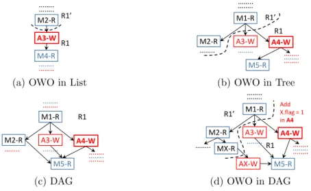
To explain scheduling of out-of-order write operations in an OSG, we start with the simplest case of an operation schedule (OS) list, followed by an OS tree and we finally address the directed acyclic graph case for OSG, as shown in Figure 8. Let us consider the first case shown in Figure 8a, where a resource’s operation schedule is a list describing the sequence of operations on it. A3-W is scheduled out-of-order by performing all the ancestor operations of the node on the dummy resource R1’, hence we split the schedule into two and move the one with all the ancestors to the dummy resource R1’. In case of a tree (shown in Figure 8b with A4-W as out-of-order write node), we additionally move all the read operation nodes (e.g., M 2-R) before any write operation, exclusively reachable from the ancestors (e.g., M 1-R) of the out-of-order write node. Finally, a tree can be transformed to a DAG by adding edges or paths from a node’s siblings or ancestors to its descendants or itself, as shown in Figure 8c. In this case, the descendants of an out-of-order write node reachable using alternative (not involving the write node, e.g., M 5-R) paths from its ancestors can be scheduled only once all of its other predecessor nodes (e.g., M 2-R) are scheduled, including the predecessor of the out-of-order write node (i.e., M 1-R). Also, the value to be used for such nodes (M 5-R) depends on two resources (R1 and R1’) and during execution either of the resource will hold valid value depending on control flow of the execution at runtime. Hence, we add a flag as a data plane resource, a match (M X) and an action node (AX) nodes to copy the value of R1’ to R1 by matching on the flag as shown in Figure 8d. This adds one MAT in the merged pipeline in order to recompose and map the MAT to the current pipeline stage using actions node not having all the write operations in ready state.
…….. M2-R M4-R A3-W ….…. ….…. …….. R1’ R1
(a) OWO in List
M2-R M5-R …….. M1-R A4-W A3-W ….…. …….. ….…. R1’ R1 ….…. ….…. ….…. (b) OWO in Tree M2-R M5-R …….. M1-R A4-W ….…. R1 ….….….….….…. ….…. …….. A3-W (c) DAG M2-R M5-R M1-R A4-W ….…. …….. ….…. R1 ….….….…. ….…. MX-R AX-W Add X.flag = 1 in A4 R1’ …….. A3-W (d) OWO in DAG
Figure 8: Out-of-order Write Operations (OWOs) and Types of Operation Schedules
4
Runtime
The Runtime system aims to manage the MATs refactored and mapped to the physical pipeline stages by Linker while restructuring the logical pipelines. It allows every P4 program’s control plane to insert only the subset of flows assigned to the program by the network operator into the MATs of the pipelines. In order to apply parallel
com-P4Bricks 4. Runtime
position operator on disjoint traffic flows, Runtime only needs to enforce traffic flow assignment constraints on programs, because Linker does not merge MATs of the dif-ferent programs while restructuring the pipelines. Runtime receives the MAT’s flow update from every P4 program’s control plane and uses the header instances UIDT to translate the flow updates from program’s header IDs to UIDs given by the Linker. The other major functionality of Runtime is to provide consistency while updating the decomposed MAT, whose sub MATs are mapped to multiple nonparallel stages of the physical pipeline. Runtime provides consistency for updates logical MATs of a program, because MATs may be vertically split by Linker when logical pipelines are restructured. Runtime maintains referential integrity among the sub MATs of a decomposed MAT while performing Add, Delete and Modify flow updates. Runtime adds, updates and modifies flow entries in a decomposed MATs while respecting the update schedule of sub MATs of the decomposed MAT, generated by the Linker.
Algorithm 5: Add Flow at Runtime in a Decomposed MAT
input : Flow F = {Mkf v, A} with match Mkf v of key field-value & actions set A mat - UUID of the table to update flow F
MATMappings - Maps every MAT to ordered list of its Sub MATs 1 Function AddFlow(F , mat, UpdateSchedList)
2 UpdateSchedList ← MATMappings.get(mat) 3 ActionSet ← F (A), MatchKFSet ← F (Mkf v)
4 foreach secondary SubMAT in ReverseOrder ( UpdateSchedList) do 5 if not HasMatch ( SubMAT, MatchKFSet) then
6 Create a new rowID for ForeignKeyField in Action of SubMAT
7 else
8 ForeignKeyField, rowID ← GetActionEntry (SubMAT, MatchKFSet)
9 ActionSet.Add(SetActionEntry (ForeignKeyField, rowID)) 10 MatchKFSet.Add(MatchKeyValue (ForeignKeyField, rowID)) 11 foreach SubMAT in UpdateSchedList do
12 if SubMAT has no flow entry for its subset of MatchKFSet then 13 Add Flow entry using subsets of MatchKFSet & ActionSet 14 Remove Mkf v & A of SubMAT from MatchKFSet & ActionSet
Linker may decompose a logical MAT by creating sub MATs using subsets of its match key fields. Flow entries of a decomposed MAT may have the same values for match key fields of some of its sub MATs. As sub MATs match flows using subsets of key fields of decomposed MATs, multiple flow entries of a decomposed MAT may share the same flow entry in sub MATs. At runtime, every secondary sub MAT assigns a row ID value, unique across the entries in the sub MAT, to its foreign key field in its action on successful match its key fields. Primary sub MATs match flows using the foreign key fields and other key fields of the decomposed MAT to further specialize the match on the flow entry and eventually execute the actions specified for the flow entry in the decomposed MAT.
Algorithm 5 realizes addition of new flow entry in a decomposed MAT. Before performing insertion, we match key fields of each sub MAT in reverse order of update schedule
P4Bricks 4. Runtime
(packet processing order) to identify every sub MAT already having flow entry for its subset key fields of new flow of the decomposed MAT (line 4). If a sub MAT does not have matching flow with its subset key fields of new flow (line 5), we create new row IDs for the foreign key field of the sub MAT. We create a match and an action for the foreign key field (lines 9-10). Next, we insert flow entries in all the sub MATs in order of update schedule generated by the Linker. If a sub MAT does not have flow entry with its sub set of key fields and foreign key fields, we add corresponding new flow entryin the sub MAT (lines 12-14).
Algorithm 6: Delete Flow at Runtime in a Decomposed MAT
input : Flow F = {Mkf v, A} with match Mkf v of key field-value & actions set A
mat - UUID of the table to update flow F
MATMappings - Maps every MAT to ordered list of its Sub MATs 1 Function DeleteFlow(F , mat, UpdateSchedList)
2 UpdateSchedList ← MATMappings.get(mat) 3 MatchKFSet ← F (Mkf v),
4 foreach SubMAT in ReverseOrder ( UpdateSchedList) do 5 ForeignKeyField, rowID ← GetActionEntry (SubMAT,
MatchKFSet)
6 MatchKFSet.Add(MatchKeyValue (ForeignKeyField, rowID)) 7 KeyMATMap.Add(ForeignKeyField, SubMAT)
8 foreach SubMAT in UpdateSchedList do 9 if SubMAT is in KeyMATMap then
10 Delete Flow entry fsub having subset of MatchKFSet 11 foreach ( ForeignKeyField, rowID) in fsub do
12 if HasMatch ( SubMAT, ( ForeignKeyField, rowID)) then
13 SecSubMAT ← KeyMATMap.GetSubMAT(ForeignKeyField)
14 Remove SubMAT match keys from MatchKFSet
To delete a flow entry of a decomposed MAT (see Algorithm 6), we need to identify the flow entry stored across the sub MATs with intermediate foreign key fields. We match sub MATs in packet processing oder to find values of all the foreign key fields set by actions in sub MATs and store the sub MAT and foreign key field mapping.(lines 4-7). We match key field values of sub MATs in order of update schedule to delete flow entry of a decomposed MAT (line 8). We delete match entry from a secondary sub MAT (line 9) only if the foreign key fields values, set by the corresponding action, are not used for matching in primary sub MATs along with key fields of the decomposed MAT. If a primary sub MAT has multiple match entries having the same values for foreign key fields and different values for flow key fields, we do not further delete entries from secondary sub MATs of the decomposed MAT (lines 11- 14).
To update a flow entry of a decomposed MAT (Algorithm 7), we identify the flow entry stored across the sub MATs along with intermediate foreign key fields. We match key fields of flow pertaining to each sub MAT in reverse order of the update schedule (lines 4-8). The last primary sub MAT matching rest of the key fields of flow and foreign key fields uniquley identifies match of entry of decomposed MAT (line 9). Finally, we update


![Figure 7: DAG representation of physical pipelines in reconfigurable devices [9]](https://thumb-eu.123doks.com/thumbv2/123doknet/13047485.382853/21.892.154.738.142.238/figure-dag-representation-physical-pipelines-reconfigurable-devices.webp)