HAL Id: cea-01765199
https://hal-cea.archives-ouvertes.fr/cea-01765199
Submitted on 14 Jan 2019
HAL is a multi-disciplinary open access
archive for the deposit and dissemination of
sci-entific research documents, whether they are
pub-lished or not. The documents may come from
teaching and research institutions in France or
abroad, or from public or private research centers.
L’archive ouverte pluridisciplinaire HAL, est
destinée au dépôt et à la diffusion de documents
scientifiques de niveau recherche, publiés ou non,
émanant des établissements d’enseignement et de
recherche français ou étrangers, des laboratoires
publics ou privés.
Design-validation of a hand exoskeleton using
musculoskeletal modeling
Clint Hansen, Florian Gosselin, Khalil Ben Mansour, Pierre Devos, Frédéric
Marin
To cite this version:
Clint Hansen, Florian Gosselin, Khalil Ben Mansour, Pierre Devos, Frédéric Marin. Design-validation
of a hand exoskeleton using musculoskeletal modeling. Applied Ergonomics, Elsevier, 2018, 68, pp.283
- 288. �10.1016/j.apergo.2017.11.015�. �cea-01765199�
Design-validation of a hand exoskeleton using musculoskeletal modeling
Clint Hansen
a,b, Florian Gosselin
c, Khalil Ben Mansour
a, Pierre Devos
a, Frederic Marin
a,∗ aSorbonne Universités, Université de Technologie de Compiègne, UMR CNRS 7338, Biomécanique et Bioingénierie, Centre de Recherche Royallieu, F-60203, Compiègne,France
bChristian-Albrechts University of Kiel, Department of Neurology, 24105 Kiel, Germany cCEA, LIST, Laboratoire de Robotique Interactive, F-91190 Gif sur Yvette, France
Exoskeletons are progressively reaching homes and workplaces, allowing interaction with virtual environments, remote control of robots, or assisting human operators in carrying heavy loads. Their design is however still a challenge as these robots, being mechanically linked to the operators who wear them, have to meet ergonomic constraints besides usual robotic requirements in terms of workspace, speed, or efforts. They have in particular tofit the anthropometry and mobility of their users. This traditionally results in numerous prototypes which are progressivelyfitted to each individual person. In this paper, we propose instead to validate the design of a hand exoskeleton in a fully digital environment, without the need for a physical prototype. The purpose of this study is thus to examine whetherfinger kinematics are altered when using a given hand exoskeleton. Therefore, user specific musculoskeletal models were created and driven by a motion capture system to evaluate the fingers' joint kinematics when performing two industrial related tasks. The kinematic chain of the exoskeleton was added to the musculoskeletal models and its compliance with the hand movements was evaluated. Our results show that the proposed exoskeleton design does not influence fingers’ joints angles, the coefficient of determination between the model with and without exoskeleton being consistently high (R2=0.93) and the nRMSE consistently
low (nRMSE = 5.42°). These results are promising and this approach combining musculoskeletal and robotic modeling driven by motion capture data could be a key factor in the ergonomics validation of the design of orthotic devices and exoskeletons prior to manufacturing.
1. Introduction
Exoskeletons have considerably advanced in recent years and such devices are progressively reaching homes and workplaces. They can be used for various applications such as interactions with virtual worlds with the sense of touch, control of remote robots, rehabilitation, and assistance with daily activities (Bogue, 2009)– (Schiele and van der Helm, 2006). The development of exoskeletons is however still a challenge. As with other robots, they have to be designed for optimal performances in terms of workspace, speeds, accelerations, and forces. However due to the specific function of an exoskeleton it requires permanent contact and is tightly linked with the user. Consequently exoskeletons also have to befitted to the user's anatomy and range of motion. From an ergonomic perspective, independent of its purpose and functionality, the most important requirement for an exoskeleton is its kinematic compatibility with the user's movements.
To meet this constraint, its number of degrees of freedom (DoF) and its compliance with the human anthropometry are key factors. Ideally, the external structure should not influence nor interfere with natural
human movements (Privitera et al., 2017), and more specifically with
those required to perform the targeted applications. To assess this, it is first required to describe in detail the tasks that must be performed with the exoskeleton. These tasks need to remain within the user's cap-abilities even when they wear the device. Indeed even if a given task appears to be rather simple, the user may not be able to perform this task if the exoskeleton does not match their actual anatomy. To validate this matching, the subject specific biomechanics need to be taken into account.
However, despite those obligations, exoskeletons are often devel-oped using CAD models and their design is evaluated post-hoc (Cempini et al., 2014). The design is rarely based on the user's anthropometry but on the 50th percentile of an anthropometric database. Consequently, numerous physical prototypes are usually required to progressively meet the requirements. Designers rely on their experience to iteratively tune the device's dimensions and characteristics tofind the best com-promise for all users or at least for a given population (e.g. adult workers in industrial environments, teenagers playing videogames). Designing exoskeletons is thus a time consuming process with multiple
∗Corresponding author.
E-mail address:[email protected](F. Marin).
iterations and physical prototypes from the initial idea to thefinal de-sign.
In contrast to such approaches, the present study employs an in silico design validation methodology, i.e. to rely on fully digital models to guide and validate the design of an exoskeleton, with a focus on the hand. The hand is one of the most complex anatomical structures of the human body with visible anatomical variations among individuals in terms of digit length and bone shapes (Durand et al., 2011). In addition its numerous DoFs, small dimensions and the large mobility of each finger make it one of the most challenging body parts in terms of ro-botics and/or orthotics (Jones, 1997), (Grebenstein et al., 2012). De-spite these difficulties, several hand exoskeleton prototypes have been developed (Heo et al., 2012), (Mozaffari et al., 2011), serving various purposes such as the creation and manipulation of virtual objects in virtual reality (VR) (Li et al., 2011), and the active movement assistance for rehabilitation (Martinez et al., 2013), (Yap et al., 2016). Systems are typically based on glove technologies or are modularly containing se-parate units for each phalanx. Indeed (Cempini et al., 2014), recently presented wearable exoskeletons that cover the DoFs and functionality of the hand. However, this system remains limited to twofingers, hence a relatively low risk of encumbrance of the exoskeleton during physical interactions. For such complex systems, in silico methods can orient the design earlier in the conception. This is particularly important for sys-tems targeting four orfive fingers.
Traditional in silico approaches used by the design and bio-mechanics communities however suffer from important limitations. Firstly, CAD software provide accurate models of the robot, but they usually integrate only simplified human models which do not reflect the high variability of limbs geometries and dimensions. Also, only simple tasks and scenarios are usually simulated compared to the complex activities found in homes and real factories. As a consequence, these tools do not precisely inform how the exoskeleton structure design in-fluences the human movement characteristics for a given user and a given task. Alternately, human movement analysis (Nigg and Herzog, 2007) and musculoskeletal modeling (Vignais and Marin, 2014) pro-pose relevant solutions and tools allowing to set-up user specific bio-mechanical hand models and to drive these models with task related movements. User-specific musculoskeletal models (Blasdel et al., 2012) based on imaging data (e.g. MRI, CT) (Valente et al., 2014) have shown their advantages over generic models and sensitivity analyses allow assessing model variations (e.g., (Gerus et al., 2013) (Hansen et al., 2014),). In turn, these tools do not, however, allow taking into account additional mechanisms such as exoskeletons. It quickly appears that both approaches are complementary and that robotic CAD modelling and biomechanics tools could be used in combination to solve the aforementioned shortcomings.
In this paper, we address this challenge by comparing biomecha-nically in silico hand movements of multiple users during two industrial assembly tasks with and without an exoskeleton. This approach allows
(Privitera et al., 2017) to optimize human well-being and overall system performance in a prototype design.
2. Methods
2.1. Hand exoskeleton's design
The exoskeleton considered in this study aims to allow dexterous interactions with digital mock-ups in Virtual Reality (VR). Such digital environments progressively replace physical prototypes to test and validate the design and assembly feasibility of new systems without having to build physical mock-ups nor perform the task in real work-shops or factories, saving space, time, and money. Also, workers can be trained in advance in VR, being fully operational as soon as they have to assemble or maintain the real system.
Here, we focus more specifically on the automotive industry. Among the new systems and procedures that will require training in the future, the maintenance of the batteries of electric vehicles are particularly challenging and were chosen as a representative use-case. After a careful analysis of the associated procedures, we selected 4 steps of the battery and other internal part disassembly. These tasks involve grasping and manipulation of small objects like nuts and cable con-nectors with thefingertips as well as the use of manual tools like pliers, screwdrivers, and socket wrenches.
Knowing that most of the hand environment interactions are achieved with the thumb, index, middle, and ring fingers (Gonzalez et al., 2014), a fourfingers device with specific 6 DoFs kinematics chains for eachfinger was proposed (seeFig. 1. In order tofit all users, this device is attached to the palm andfingertips and runs in parallel with the hand without having its joints aligned with the user's ones. To allow efficient interaction with virtual environments, it should be able to apply forces up to 10N on thefingertips (Gosselin et al., 2013). To minimize its weight and bulkiness, we decided to use a single actuator to render the forces that occur when grasping a virtual object while fingertip haptic devices attached at the tip of the robots are used to deform the pulp to simulate the object's weight or texture.
Then the actuators, reducers, kinematics, dimensions andfingertip devices were optimized with a CAD software (Solidworks, Dassault Systems, Vélizy-Villacoublay, France) in order to allow maximum range of motion (allfingers can move in abduction-adduction and in flexion extension over a large range of motion and the thumb can be moved in opposition and placed in contact with all otherfingertips) while mini-mizing the size and weight of the device as well as the space between thefingers and the exoskeleton.
As shown inFig. 1, the CAD optimization was performed using a standardized hand model. Its dimensions were adjusted so as to corre-spond to the 50thpercentile of the adult population, this percentile and associated dimensions corresponding to a subset of individuals whose
Fig. 1. The proposed MANDARIN hand exoskeleton design (left) and its kinematics (right).
To validate the device's kinematic compatibility with different users, and demonstrate that complex combined movements of all fin-gers are feasible before manufacturing a prototype, we tested this de-sign in a biomechanical environment as will be explained below. 2.2. User specific biomechanical modeling
In order to test the exoskeleton compliance with human hand movements for different user anatomies, we developed subject specific biomechanical models. The experimental procedure included the de-termination of subject specific hand skeleton geometries by medical imaging and the identification of the hand's kinematics during a 3D motion capture session.
Users: Three users (age: 31.7 ± 9.1, body mass: 72.3 ± 13.7 kg, height: 1.73 ± 0.11m) voluntarily participated in the experiment after signing a statement of informed consent pertaining to the experimental procedure as required by the Helsinki declaration and the local Ethics Committee. As hand size can be a limiting parameter during the use of exoskeletons, we considered hands representing the size of small (5th percentile), average (50th percentile) and large (95th percentile) users, these percentiles still corresponding to anthropometric data of American Army personnel (Greiner, 1991).
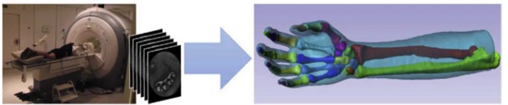
Medical imaging: 3D imaging by a 1.5 T MRI Device (GE Signa HDx™) with a spatial resolution of 0.3 × 0.3 × 0.5 mm3of the hands and forearms of the three users was performed and the 3D internal geometry of the personalized joint model was obtained with a 3D image data visualization software (ScanIP, Simpleware©) (Hansen et al., 2014) (seeFig. 2).
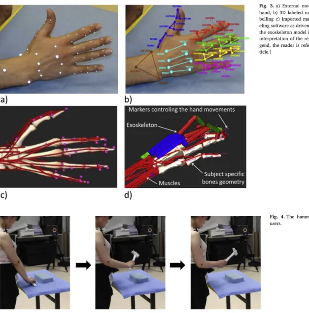
Hand motion capture: to identify hand movements and drive the biomechanical model, 3D movement analysis of the hand was per-formed using an 18-camera motion analysis system (T160 series, VICON, Oxford Metrics Ltd, Oxford, UK) at 100 Hz. Three markers were positioned on each segment and phalanx of the hand (Buczek et al., 2011), (Chang and Pollard, 2007). A total of 53 markers werefixed on the hand and the wrist (seeFig. 3a).
Then markers were 3D reconstructed and labeled using the software associated with the motion capture system (Nexus 2.1, VICON, Oxford Metrics Ltd, Oxford, UK, seeFig. 3b).
The internal geometry and the 3D marker positions were then im-ported into a musculoskeletal modeling environment (SIMM, Motion Analysis Corporation, Santa Rosa, CA, see Fig. 3c). Based on the in-ternal geometries obtained from the medical imaging, a complete musculoskeletal model consisting of 28 rigid segments and 36 joints wasfirst implemented and scaled for each user. This model contains 27 bones: the carpal bones, the metacarpal bones, the proximal phalanges, the intermediate phalanges and the distal phalanges (Levangie and Norkin, 2005), (Kapandji, 2007). These bones are connected by the midcarpal (MC) joint (2 DoF), the carpometacarpal (CMC) joints (2 DoF), the metacarpophalangeal (MCP) joints (2 DoF), the proximal interphalangeal (PIP) joints (1 DoF) and the distal interphalangeal (DIP) joints (1 DoF). For the purpose of integrating the kinematic chain of the exoskeleton the model was simplified. The relative movements of the carpal bones as well as the movements of the metacarpals of the indexfinger, middle finger and ring finger relative to the carpus being of small amplitudes, they were not provided with a DoF. Contrary to the otherfingers, the thumb has only two phalanges that form the inter-phalangeal (IP) joint (1 DoF). It is located in front of the palm and the
fingers due to the trapeziometacarpal (TMC) joint (3 DoF) (Kapandji, 2007). Thisfinal model thus includes only 16 links (17 with the wrist) with 22 DoF (24 with the wrist).
Finally, the hand's exoskeleton was integrated within this model (seeFig. 3d). The device is modeled as a set of rigid bodies with the same kinematical chain as the exoskeleton CAD model (seeFig. 1). The linkage between the hand's exoskeleton and the musculoskeletal model arefixed joints located at the dorsum of the hand and the distal pha-langes of the thumb, index, middle and ringfinger. The model, with or without the exoskeleton, was then driven by the 3D positions of the motion capture markers. In order to test the exoskeleton compliance with human hand movements during the performance of real industrial tasks, we invited each user to perform two industrial related tasks re-presentative of the gestures performed when disassembling the battery: the use of a hammer and a screwdriver.
Motion capture: during the motion capture session, users were asked to pick the tools from a table and perform the tasks. During the hammer task user were asked to drive a nail in timber (seeFig. 4). During the screwdriver task, user turned a screw downward into the timber. These tasks involve similar movements as the manipulation of tools during the industrial task. Users were instructed to maintain an upright posture while one hand was holding the tool and the other was supporting either the nail or the screw. Each task was performed three times within one trial.
Control of the biomechanical model: for each user the motion capture sessions’ data were used to drive the biomechanical model. The kinematics of the hand and the forearm posture of the users were not measured directly, but derived from bone orientations in combination with the 3D marker positions. The 3D marker positions were exported in a C3D format, integrated in the musculoskeletal model (SIMM, MA, USA) and used to drive the kinematics of the model.
2.3. Statistical analysis
For the three users, the anatomical joint kinematics was exported from the musculoskeletal modeling environment and post-processing was performed with custom written software developed in the MATLAB environment (MathWorks, Natick, MA). The analysis included the comparison of the kinematic joint angles (flexion/extension) of the model with and without exoskeleton for the TMC and IP joints of the thumb and for the MCP, PIP, and DIP joints of the index, middle and ringfingers.
The coefficients of determination (R2
) based on Pearson's correla-tion, linear regressions and the normalized mean square error (nRMSE) were calculated over the time-series of each trial (three repetitions), to describe differences between the two models. Then, descriptive ana-lyses of the range of motion of the eleven joints were performed fol-lowed by interferential statistical analyses. Gaussian distribution of variables was confirmed with Shapiro-Wilk tests and consequently followed by paired t-tests (Moore and McCabe, 2006). For all statistical analyses, Matlab (MathWorks, Natick, MA) was used. The significance level was set to p < 0.05.
Fig. 2. High resolution MRI acquisition and personalized hand internal model.
3. Results 3.1. Joint kinematics
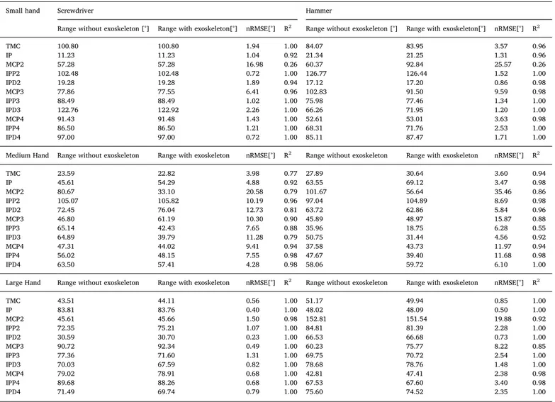
During the manipulation of the hammer and screwdriver, the range of motion were the highest for the MCP and TMC joints, followed by the PIP and DIP joints (Table 1). There was no significant difference in the range of motion without (M = 69.10, SD = 26.37) and with exoske-leton (M = 66.30, SD = 27.70) when using the screwdriver; t (32) = 1.51, p = 0.14, 95% CI [-0.97, 6.57]. Similarly, no significant difference was seen in the range of motion without (M = 66.32, SD = 28.59) and with exoskeleton (M = 65.86, SD = 29.17) when using the hammer; t(32) = 0.23, p = 0.83, 95% CI [-3.71, 4.63]. The coefficient of determination between the respective joint angles was consistently high (R2 > 0.55) and the normalized Root Mean Square Error (nRMSE) consistently small except for DIP2 (seeFig. 5, average results for the three users).
4. Discussion
The present research evaluated the impact of an exoskeleton on the
(R2=0.93) and the nRMSE consistently low (nRMSE = 5.42°). During
the hammer task, we observed smaller deviations compared to the screwdriver task and as a result, the explained variance was a little smaller. The extent of the kinematic differences between the model with and without exoskeleton over the three repetitions (for each user) corresponds to 11% and 12% (hammer and screwdriver). This is com-parable to the 11° found by (Guo et al., 2014) and similar to the maximum joint angle difference of 18° by (Li et al., 2011) for a one finger model. The comparison with other studies is complicated as the model specifications are often unmatched and the metrics are chosen differently e.g. (Jo et al., 2017). Hand exoskeletons are often deployed clinically to assist motion e.g. improve force development (Heo et al., 2012) or finger flexion (Chen and Lum, 2016). Associated with the mechanical constraints of the exoskeleton a slight change in the kine-matics could be expected which was also shown for EMG activity during a study that aimed to assess the physiological consequences of using an upper limb exoskeleton during manual handling tasks (Theurel et al., 2018).
The combination of robotics CAD and biomechanical tools allows assessing the performance of candidate exoskeleton designs and the procedure is different to other studies which have evaluated the fit and
Fig. 3. a) External motion capture markersfixed on the hand, b) 3D labeled markers after reconstruction and la-belling c) imported markers in the musculoskeletal mod-eling software as driven markers (in pink) d) integration of the exoskeleton model in the musculoskeletal models. (For interpretation of the references to colour in thisfigure le-gend, the reader is referred to the Web version of this ar-ticle.)
Fig. 4. The hammer task performed by one of the users.
associated with the industrial task were neglected as the application was for industrial training tasks and not for rehabilitation or medical purposes. Integrating multiple kinematic chains in musculoskeletal models is an interesting method to test exoskeletons or orthotic devices prior to fabrication. The design and the functionalities of the device can be adapted and tested against the real hand kinematics. This is espe-cially important because movements are rarely identical (Latash et al.,
2002) and this methodology allows evaluating the advantages and flaws of several designs with consistent industrial-relevant kinematics (Vignais et al., 2013) to avoid over-dimensioned design (Chammas et al., 2015). The use of three hand sizes ranging from the 5th to the 95th percentile of the population (Greiner, 1991) allowed adaptation of the exoskeleton to different hand sizes without constraining the fingers range of motion. The database from the anthropometric survey of
Table 1
Ranges of each joint [°] during the screwdriver and hammer movements with and without the exoskeleton. Small hand Screwdriver Hammer
Range without exoskeleton [°] Range with exoskeleton[°] nRMSE[°] R2 Range without exoskeleton [°] Range with exoskeleton[°] nRMSE[°] R2
TMC 100.80 100.80 1.94 1.00 84.07 83.95 3.57 0.96 IP 11.23 11.23 1.04 0.92 21.34 21.25 1.31 0.96 MCP2 57.28 57.28 16.98 0.26 60.37 92.84 25.57 0.26 IPP2 102.48 102.48 0.72 1.00 126.77 126.44 1.52 1.00 IPD2 19.28 19.28 1.89 0.94 17.12 17.20 0.86 0.98 MCP3 77.86 77.55 6.41 0.96 102.83 91.50 9.59 0.98 IPP3 88.49 88.49 1.02 1.00 75.98 77.46 1.34 1.00 IPD3 122.76 122.92 2.26 1.00 66.26 71.95 1.20 1.00 MCP4 91.43 91.48 1.43 1.00 52.61 53.01 3.63 0.98 IPP4 86.50 86.50 1.21 1.00 68.31 71.76 2.53 1.00 IPD4 97.00 97.00 0.72 1.00 85.11 87.47 1.71 1.00 Medium Hand Range without exoskeleton Range with exoskeleton nRMSE[°] R2 Range without exoskeleton Range with exoskeleton nRMSE[°] R2
TMC 23.59 22.82 3.98 0.77 27.89 30.64 3.60 0.94 IP 45.61 54.29 4.88 0.92 63.55 69.12 3.47 0.98 MCP2 80.67 33.10 20.58 0.79 101.67 56.64 35.46 0.86 IPP2 105.07 105.82 10.19 0.96 97.04 104.89 8.69 0.98 IPD2 72.45 76.04 12.73 0.81 63.72 62.86 5.84 0.96 MCP3 46.80 61.19 10.30 0.90 45.89 48.97 15.87 0.88 IPP3 65.14 42.43 7.65 0.88 35.96 18.75 6.28 0.55 IPD3 64.89 39.79 11.28 0.79 50.75 31.44 4.56 0.92 MCP4 47.31 44.02 9.41 0.94 37.58 43.73 11.97 0.94 IPP4 56.02 48.15 7.55 0.98 47.67 39.40 11.68 0.98 IPD4 63.50 57.41 4.28 0.98 58.06 59.72 6.10 1.00 Large Hand Range without exoskeleton Range with exoskeleton nRMSE[°] R2 Range without exoskeleton Range with exoskeleton nRMSE[°] R2
TMC 43.51 44.11 0.56 1.00 51.17 49.94 0.85 1.00 IP 83.81 83.76 0.40 1.00 48.02 48.09 0.50 1.00 MCP2 45.61 45.66 1.50 0.98 152.81 151.54 19.88 0.92 IPP2 72.35 75.21 1.07 1.00 84.81 81.39 2.28 1.00 IPD2 30.59 30.70 0.23 1.00 66.53 66.68 0.73 1.00 MCP3 90.72 92.34 0.49 1.00 60.23 75.77 8.22 0.85 IPP3 77.36 71.60 1.31 1.00 69.75 70.72 2.54 1.00 IPD3 70.03 67.59 0.82 1.00 78.68 78.76 1.48 1.00 MCP4 79.02 78.91 0.68 1.00 42.81 47.41 2.38 0.98 IPP4 89.68 88.26 0.68 1.00 67.53 67.60 3.40 0.98 IPD4 71.49 69.74 0.79 1.00 75.60 74.52 2.35 1.00 Range of motion with the exoskeleton alsofitted a significant proportion of the range of motion without the exoskeleton, R2= 0.85, F(1, 32) = 180.89, p < 0.001 for the screwdriver
and for the hammer R2= 0.84, F(1, 32) = 165.56, p < 0.001.
Fig. 5. Mean nRMSE and mean correlation of the joint kinematics with and without exoskeleton throughout the executed movements. The nRMSE shows small values while the correlation is consistently high.
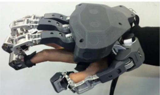
American Army personnel (Greiner, 1991) may be a limiting factor if the percentiles do not correspond to the local community (e.g. gender, ethnicity, age). However the databasefit the variety of test users and therefore we think that the choice was acceptable. We decided there-fore to go further in the design process and manufactured and as-sembled a prototype. In the current case the glove was attached to the back of the hand andfingertips only, leaving the proximal and inter-mediate phalanges free and maintaining a simple and light design (see
Fig. 6).
The final product combines the exoskeleton geometry and kine-matics obtained from the CAD design performed by roboticists and the hand geometry and kinematics obtained from musculoskeletal mod-eling.
5. Conclusion
This study demonstrated the feasibility to validate an exoskeleton design via biomechanical modelling. The 3D movement analysis driven by user- and task-specific data allowed testing and validation of the exoskeleton design in a CAD environment. If necessary, this design could have been further adapted and improved over the design itera-tions. Such cross-pollination between designers, engineers and bio-mechanists, and the maturation of the interoperability between CAD and musculoskeletal models should allow for enhanced anticipation and optimization of device design regardless of the human variability. It is worth noting that such evaluation of the compliance of the exoske-leton with the current musculoskeletal model using motion capture data could also prove useful for testing future design improvements as these evaluations could be performed without additional measure-ments. As a perspective, a more complex musculoskeletal model could be generated to evaluate muscle activities (Theurel et al., 2018) and joint torques (Agarwal et al., 2016), if necessary.
Acknowledgments
This research was partly supported by the“Agence Nationale de la Recherche” (Mandarin project - ANR-12-CORD-0011, labeled by “Cap Digital Paris Région”, the French cluster for digital contents and ser-vices).
References
Agarwal, P., Neptune, R.R., Deshpande, A.D., Apr. 2016.“A simulation framework for virtual prototyping of robotic exoskeletons. J. Biomech. Eng. 138 (6), 061004.
Blasdel, A., Ikegami, Y., Ayusawa, K., Nakamura, Y., 2012. Balancing Anatomy and Function in a Musculoskeletal Model of Hands. pp. 5130–5135.
Bogue, R., Aug. 2009. Exoskeletons and robotic prosthetics: a review of recent develop-ments. Ind. Robot. Int. J. 36 (5), 421–427.
Buczek, F.L., Sinsel, E.W., Gloekler, D.S., Wimer, B.M., Warren, C.M., Wu, J.Z., Jun. 2011.
Kinematic performance of a six degree-of-freedom hand model (6DHand) for use in occupational biomechanics. J. Biomech. 44 (9), 1805–1809.
Cempini, M., Marzegan, A., Rabuffetti, M., Cortese, M., Vitiello, N., Ferrarin, M., 2014. Analysis of relative displacement between the HX wearable robotic exoskeleton and the user's hand. J. NeuroEngineering Rehabil. 11 (1), 147.
Chammas, A., Quaresma, M., Mont'Alvão, C., 2015. A closer look on the user centred design. Procedia Manuf. 3, 5397–5404.
Chang, L.Y., Pollard, N.S., Jan. 2007. Constrained least-squares optimization for robust estimation of center of rotation. J. Biomech. 40 (6), 1392–1400.
Chen, T., Lum, P.S., 2016.“Hand rehabilitation after stroke using a wearable, high DOF, spring powered exoskeleton. In: 2016 38th Annual International Conference of the IEEE Engineering in Medicine and Biology Society (EMBC), pp. 578–581.
Durand, S., Marin, F., Oberlin, C., Ho Ba Tho, M.-C., Oct. 2011. Morphogenesis of the human palma arch using three-dimensional geometric modeling. Clin. Anat. 24 (7), 874–879.
Gerus, P., Sartori, M., Besier, T.F., Fregly, B.J., Delp, S.L., Banks, S.A., Pandy, M.G., D'Lima, D.D., Lloyd, D.G., Nov. 2013. Subject-specific knee joint geometry improves predictions of medial tibiofemoral contact forces. J. Biomech. 46 (16), 2778–2786.
Gonzalez, F., Gosselin, F., Bachta, W., Oct. 2014. Analysis of hand contact areas and interaction capabilities during manipulation and exploration. IEEE Trans. Haptics 7 (4), 415–429.
Gosselin, F., 2013. Guidelines for the design of multi-finger haptic interfaces for the hand. In: In: Padois, V., Bidaud, P., Khatib, O. (Eds.), Romansy 19– Robot Design, Dynamics and Control, vol. 544. Springer Vienna, Vienna, pp. 167–174.
Grebenstein, M., Chalon, M., Friedl, W., Haddadin, S., Wimbock, T., Hirzinger, G., Siegwart, R., Nov. 2012. The hand of the DLR hand arm system: designed for inter-action. Int. J. Robot. Res. 31 (13), 1531–1555.
Greiner, T., 1991. Hand Anthropometry of US Army Personnel. No TR-92011 ARMY NATICK Res. Dev. Eng. Cent. MA.
Guo, S., Zhang, F., Wei, W., Zhao, F., Wang, Y., 2014.“Kinematic analysis of a novel exoskeletonfinger rehabilitation robot for stroke patients. In: 2014 IEEE International Conference on Mechatronics and Automation, pp. 924–929.
Hansen, C., Ben Mansour, K., Devos, P., Marin, F., Aug. 2014. Small cause, great impact: a sensitivity study in musculoskeletal modelling of the hand. Comput. Methods Biomech. Biomed. Engin. 17 (Suppl. 1), 114–115.
Heo, P., Gu, G.M., Lee, S., Rhee, K., Kim, J., May 2012. Current hand exoskeleton tech-nologies for rehabilitation and assistive engineering. Int. J. Precis. Eng. Manuf. 13 (5), 807–824.
Jo, I., Lee, J., Park, Y., Bae, J., 2017. Design of a wearable hand exoskeleton for exercising flexion/extension of the fingers. In: 2017 International Conference on Rehabilitation Robotics (ICORR), pp. 1615–1620.
Jones, L., Feb. 1997. Dextrous hands: human, prosthetic, and robotic. Presence Teleoperators Virtual Environ. 6 (1), 29–56.
Kapandji, A.-I., 2007. The Physiology of the Joints, Volume 1: Upper Limb, sixth ed. Churchill Livingstone, London.
Latash, M.L., Scholz, J.P., Schöner, G., Jan. 2002. Motor control strategies revealed in the structure of motor variability. Exerc Sport Sci. Rev. 30 (1), 26–31.
Levangie, P., Norkin, C., 2005. Joint Structure and Function: a Comprehensive Analysis, fourth ed. F.A. Davis Company, Philadelphia, PA.
Li, Jiting, Zheng, Ruoyin, Zhang, Yuru, Yao, Jianchu, 2011. iHandRehab: an Interactive Hand Exoskeleton for Active and Passive Rehabilitation. pp. 1–6.
Martinez, J.A., Ng, P., Lu, Son, Campagna, M.S., Celik, O., 2013. Design of Wrist Gimbal: a Forearm and Wrist Exoskeleton for Stroke Rehabilitation. pp. 1–6.
Moore, D.S., McCabe, G., 2006. Introduction to the Practice of Statistics. W. H. Freeman and Company.
Mozaffari, F.M., Troncossi, M., Parenti, C.V., 2011. State-of-the-Art of Hand Exoskeleton Systems. Universit di Bologna.
Nigg, B., Herzog, W., 2007. Biomechanics of the Musculo-skeletal System, third ed. John Wiley & Sons, New York City.
Privitera, M.B., Evans, M., Southee, D., Mar. 2017. Human factors in the design of medical devices– approaches to meeting international standards in the European Union and USA. Appl. Ergon. 59, 251–263.
Schiele, A., van der Helm, F., 2006. Kinematic design to improve ergonomics in hu-manmachine interaction. IEEE Trans. Neural Syst. Rehabil. Eng. 14 (4), 456–459.
Theurel, J., Desbrosses, K., Roux, T., Savescu, A., Feb. 2018.“Physiological consequences of using an upper limb exoskeleton during manual handling tasks. Appl. Ergon. 67 (Suppl. C), 211–217.
Valente, G., Pitto, L., Testi, D., Seth, A., Delp, S.L., Stagni, R., Viceconti, M., Taddei, F., Nov. 2014. Are subject-specific musculoskeletal models robust to the uncertainties in parameter identification? PLoS One 9 (11), e112625.
Vignais, N., Marin, F., 2014. Analysis of the musculoskeletal system of the hand and forearm during a cylinder grasping task. Int. J. Ind. Ergon. 44 (4), 535–543.
Vignais, N., Miezal, M., Bleser, G., Mura, K., Gorecky, D., Marin, F., Jul. 2013. Innovative system for real-time ergonomic feedback in industrial manufacturing. Appl. Ergon. 44 (4), 566–574.
Yap, H.K., Lim, J.H., Nasrallah, F., Cho Hong Goh, J., Yeow, C.-H., May 2016. Characterisation and evaluation of soft elastomeric actuators for hand assistive and rehabilitation applications. J. Med. Eng. Technol. 40 (4), 199–209.
Fig. 6. The prototype of the MANDARIN hand exoskeleton validated in silico before manufacturing.