ORIGINAL ARTICLE
Ultra-high-resolution dual-source CT for forensic dental
visualization
—discrimination of ceramic
and composite fillings
C. Jackowski&M. Wyss&A. Persson&M. Classens&
M. J. Thali&A. Lussi
Received: 22 October 2007 / Accepted: 18 January 2008 / Published online: 12 March 2008 # Springer-Verlag 2008
Abstract Dental identification is the most valuable method to identify human remains in single cases with major postmortem alterations as well as in mass casualties because of its practicability and demanding reliability. Computed tomography (CT) has been investigated as a supportive tool for forensic identification and has proven to be valuable. It can also scan the dentition of a deceased within minutes. In the present study, we investigated currently used restorative materials using ultra-high-resolution dual-source CT and the extended CT scale for the purpose of a color-encoded, in scale, and artifact-free visualization in 3D volume rendering. In 122 human molars, 220 cavities with 2-, 3-, 4- and 5-mm diameter were prepared. With presently used filling materials (different composites, temporary filling materials, ceramic, and liner), these cavities were restored in six teeth for each material and cavity size (exception amalgam n=1). The teeth were CT scanned and images reconstructed using an
extended CT scale. Filling materials were analyzed in terms of resulting Hounsfield units (HU) and filling size repre-sentation within the images. Varying restorative materials showed distinctively differing radiopacities allowing for CT-data-based discrimination. Particularly, ceramic and composite fillings could be differentiated. The HU values were used to generate an updated volume-rendering preset for postmortem extended CT scale data of the dentition to easily visualize the position of restorations, the shape (in scale), and the material used which is color encoded in 3D. The results provide the scientific background for the application of 3D volume rendering to visualize the human dentition for forensic identification purposes.
Keywords Forensic radiology . Dental identification . Dental filling materials . Extended CT scale . Dual source CT
Introduction
In cases of single unknown bodies or multiple unknown bodies in mass fatality incidents, to accurately and rapidly identify the victims is important not only for juridical reasons. Dental identification plays a major role in the identification of corpses with postmortem alterations such as advanced stages of putrefaction or burning. On the other hand, dental identification is often used in mass casualties either from natural disasters or due to armed conflicts as it
has a high reliability [1,2].
Having already been introduced as a postmortem investi-gation tool, computed tomography (CT) is currently evaluated
for varying purposes [3–10]. CT can also contribute to the
purpose of identification manifold [11–16]. Focusing the
research on the dental CT imaging for identification purposes, a few studies have already demonstrated the
DO00224; No of Pages
C. Jackowski (*)
:
M. J. ThaliCenter of Forensic Imaging and Virtopsy, Institute of Forensic Medicine, University of Bern, Bühlstreet 20,
3012 Bern, Switzerland
e-mail: [email protected] M. Wyss
:
A. LussiDepartment of Preventive, Restorative and Paediatric Dentistry, University of Bern,
3010 Bern, Switzerland C. Jackowski
:
A. PerssonCenter for Medical Image Science and Visualization (CMIV), University of Linköping,
58185 Linköping, Sweden M. Classens
Department of Diagnostic Radiology, Lindenhofspital, Bremgartenstrasse 117,
feasibility of CT data [17–19]. The main problem mentioned within the published work was to overcome the well-known streak artifacts caused by the dental restorative material itself that should actually be visualized as it contains necessary individualizing characteristics.
This problem could be solved by using the extended CT scale technique for image reconstruction as it extends the radiopacity values ten times, which can be represented within
the CT images by gray values [19]. Thereby, most of the
filling materials lose the streak artifact as the radiopacity does not exceed the upper scale limit anymore. The first experiments investigating the CT-data-based visualization of dental restorations using the extended CT scale technique were carried out on restored teeth, which had been extracted
for different reasons [19]. This first study [19] was a
feasibility study lacking precise information on the filling material used in terms of composition, age of the restoration, and supplier, as well as unknown real filling dimensions. Of course, the number of investigated restorations was also too
low to statistically substantiate the results [19].
Therefore, the aim of the present study was to increase the knowledge about the predominant radiopacity behavior of recently used filling materials with special focus on composite fillings. These are the materials the forensic examiners will increasingly have to deal with in the future as the formerly widespread use of amalgam will slowly disappear during the next decades. These materials will be more and more improved in terms of tooth coloration which further complicates the visual identification during an external examination of a corpse. As in the initial study, it was intended to subsequently implement the newly gained knowledge in a 3D volume-rendering (VR) algorithm for postmortem extended CT scale data that can easily visualize the dentition not only in terms of filling location but also in terms of filling material used as well as filling size and shape.
Materials and methods
Ten different materials used for restorative purposes (temporary, permanent, liner, and adhesives; displayed in
Table 1) were investigated and 122 human molars were
prepared with cavities of 2-, 3-, 4-, and 5-mm diameter
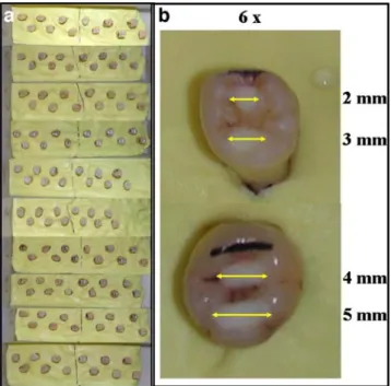
(Fig.1). Two cavities of either 2 and 3 or 4 and 5 mm were
prepared in each tooth. For the ceramic fillings, only one cavity per tooth could be reasonably prepared as they are applied as prepared solid blocks. Knowing from the initial study that amalgam distinctively exceeds the upper 30,710 Hounsfield Unit (HU) limit of the extended CT scale (on the used Siemens CT), the amalgam fillings were limited to one in each size, respectively. This resulted in 220 restorative fillings of known restorative material and
dimension to be investigated. Table
1 Investigated materials used for dental restorations, characteristics, and supplier are given. Also adhesives and liner were included as they might influence the appearance of the definite material which they come along with T emporary filling materials Permanent filling materials Liner and adhesives Name IRM Ketac Fil T etric Flow T etric Evo Ceram Dyract eXtra V itablocs Mark II Oralloy Magicap S 3M V itrebond Optibond Xeno III Characteristics
Polymer reinforcement zinc
oxide-eugenol
Glas-ionomer- cement
Light-curing flowable hybrid composite
Light-curing nanohybrid composite Fluoridated glass filler with acid-modifier monomers Fine-partic le feldspar cera m ic b loc ks
Non- gamma-2 amalgam
Light
cure
glass ionomer liner/base
F illed, li ght-cur e tot al-etch ad hesive b onding syst em
Self- etching dental adhesive
Supplier DENTSPL Y DeT rey Gmbh, Dreiech/ Baar , Switzerland ESPE, D en ta l-Me diz in G m b h & C o. KG, Seef eld, Ger m any Ivoclar V ivadent AG, Schaan, Liechtenstein
Ivoclar Vivadent AG,
Schaan, Liechtenstein DENTSPL Y DeT rey Gmbh, Konstanz, Germany VIT A Za hn fa br ik H. Rauter Gmbh and C o. KG, Bad Säckingen, Germ any Coltène /
Whaledent AG, Altstätten, Switzerland
3M Dental Products, Laboratories 3M Santé, Pithiviers, France Kerr Dentistry , Orange, USA DENTSPL Y DeT rey Gmbh, Konstanz, Germany
For CT scanning, the roots of the teeth were embedded in Optosil® Comfort (Heraeus Kulzer, Hanau, Germany), an edentulous impression system that perfectly replaces the jaw bone in CT experiments as it shows an X-ray attenuation of 150–200 HU. This as well as immersing
the teeth in artificial saliva [20] during scanning simulated
enoral conditions with the aim to reduce partial volume effects at borders and to facilitate an application of the study results on whole in situ dentitions. The teeth were scanned on a dual-source CT scanner (Definition, Siemens Medical, Erlangen, Germany) using ultra-high-resolution
settings (z-Sharp™ technology). Raw data acquisition
120 kv, 182 mAs, 12×0.3-mm collimation, rotation time 1 s, pitch 0.9, and a 50 mm field of view image re-construction in a 512 matrix resulted in a voxel size of 0.1× 0.1×0.24 mm (U70 reconstruction kernel and extended CT scale).
The maximum and minimum HU values of each filling were assessed on a radiological workstation (Leonardo, Siemens Medical, Erlangen, Germany). Furthermore, the maximum and minimum value for the dentine and the maximum value for the enamel were measured in each tooth (except for the amalgam restored teeth).
The mean values and standard deviations (SD) were calculated for every filling material and filling size as well as for every filling material including all filling sizes. The HU ranges obtained were used to redefine the preset settings for a volume-rendering software (Inspace, Syngo, Siemens Medical, Erlangen, Germany). The resulting
software application was applied to a CT data set of teeth containing five different filling materials for validation.
Results
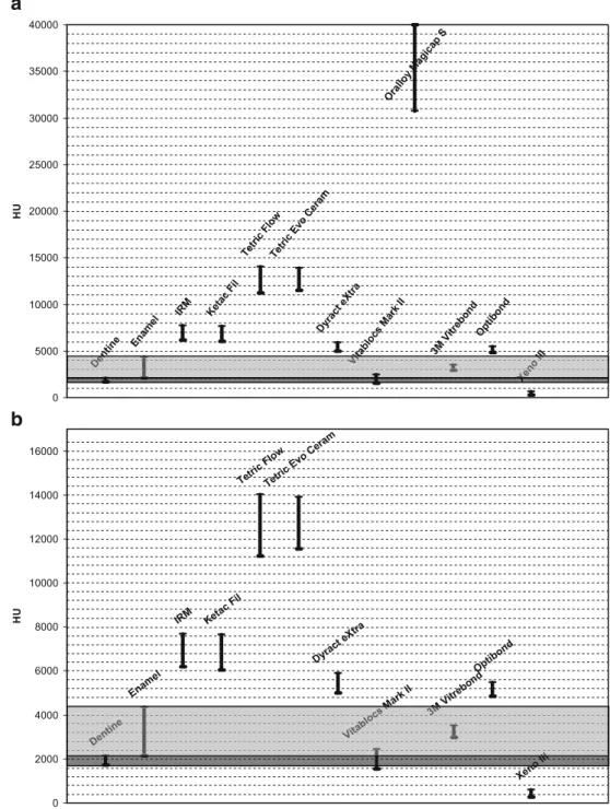
The dentine covered a range from 1,717 HU (SD 63.9 HU) to 2,130 HU (SD 72.8 HU) and the enamel reached a mean
of 4,350 HU (SD 89.7 HU) as indicated in Fig.2.
Table2 displays the obtained mean values and standard
deviations of the maximum and minimum HU
measure-ments. Figure 2 gives an overview on the HU ranges that
represent each restorative material on the extended CT scale based on our measurements and compares them to the obtained values of the tooth dentine and enamel.
Both temporary filling materials, namely IRM and Ketac Fil, showed comparable X-ray attenuation between ~6,000 and ~7,700 HU and cannot therefore be clearly differenti-ated from each other by their HU values. However, to separate both as temporary filling from definite restorations becomes possible as they are the only that cover this HU range.
The permanent fillings showed different radiopacities. Tetric Flow and Tetric Evo Ceram presented with the highest nonmetallic values, both covered a range of ~11,200 to ~14,000 HU. In contrast, Dyract eXtra demon-strated a range from ~5,000 to ~5,900 HU and was thereby only slightly more opaque than tooth enamel.
The ceramic fillings (Vitablocs Mark II) were difficult to assess for two reasons. They have to be embedded in a thin layer of special ceramic adhesive (Variolink 2, Ivoclar Vivadent, Schaan, Lichtenstein), which radiologically behaved
like the highly opaque composites (see Table2and Fig.3) and
the radiopacity range of ceramic itself was within the HU range of the dentine or even lower.
Amalgam could not be represented within the 2D images by its real HU value as it exceeded the upper limit of 30,710 HU. Therefore, it was always measured as the upper scale limit value and is given as 30,710 HU within the tables. The investigated adhesives and liner showed radio-pacities comparable to enamel, slightly above enamel or comparable to bone. Knowing that none of these has a high radiopaque X-ray behavior and all of them are expected to occur only in very thin layers around definite restorations, they can be disregarded within the volume-rendering preset.
Discussion
The present study aimed at a reevaluation of the results
from a feasibility study published in 2006 [19]. The cited
study showed promising results but was lacking in various aspects, such as insufficient information about the used Fig. 1 Investigated teeth. a Teeth were embedded in an edentulous
impression system (yellow) that has a radiopacity comparable to bone. b For each investigated material six cavities of 2-, 3-, 4-, and 5-mm diameter were prepared and restored
filling materials and exact filling size. Furthermore, the number of investigated teeth was also low; therefore, a prospective study that would provide the background for a further implementation of the extended CT scale for the purpose of dental visualization became necessary.
When planning the study, restorative materials were chosen that are the most widely used at least in central Europe (in the authors’ experiences). Of course, it was impossible to include every material that has been used or is used around the world. As it was expected that most of
the material groups differed only slightly with different suppliers, the study concentrated on imaging the material groups. Materials that are used during the restorative process to prepare the cavity for the filling and act as a glue for a filling were also included because they could remain visible as thin layers around the filling when having distinctively differing HU values. Fortunately, the measure-ments showed that both of the adhesives and also the Vitrebond as a liner have radiopacities which do not differ greatly from normal teeth. Therefore, and as they are only
Mark II M
Xeno
entine Vitablocs Mark II III
ne nt De ocs bl Vit 3 X Enamel
IRM Ketac Fil
Tetric FlowTetric Evo Ceram
Dyract eXtra Optibond 0 2000 4000 6000 8000 10000 12000 14000 16000 HU Enamel
IRM Ketac Fil
Tetric FlowTetric Evo Ceram
Dyract eXtra Oralloy Magica p S 3M Vitrebond Optibond 0 5000 10000 15000 20000 25000 30000 35000 40000 HU
b
a
Fig. 2 Graphical HU range de-lineation based on the values obtained in the investigated re-storative materials. a With amalgam. Note that the lower and upper limit of amalgam’s radiopacity cannot reliably be assessed. Within the images, it is given with the upper limit of the actual extended CT scale. But it is likely that it distinctively exceeds this value. b Without amalgam. Note that only Vitablocks (ceramic), liner, and an adhesive have radiopacities that are at the level of teeth or loweroccurring as thin layers around the filling, the results justify that they can be ignored within the VR preset.
To compare a view on a volume-rendered 3D model to a conventional radiograph of the dentition for the purpose of identification, it is important that not only the location of the restoration but also the filling shape is correctly displayed within the VR image. To address this require-ment, it was indispensable to investigate fillings with at least one known filling diameter. Therefore, the teeth were prepared with cavities of known width in four different
sizes. This was intended to rule out or recognize and further investigate size-dependent visualization errors. Fortunately, there was no obvious size-dependent change in radiopacity. Tests of the preset showed also that all four filling sizes were displayed correctly within the 3D
images (see Fig. 3).
There are two permanent filling materials that do challenge imaging by CT. First of all and already known from the feasibility study, the amalgam needs to be discussed. Being a composition of different metals such as Table 2 Investigated materials and maximal and minimal HU values that were obtained instead of the mean as they are needed to reasonably set the borders of the HU trapezoids within the VR presets for discrimination
Note at the example images below that the radiopacity of the ceramic (Vitablocs Mark II) filling itself is comparable to the dentine. However, there is a thin margin of very dense material around the ceramic, which indicates a radiopaque adhesive as bonding substance
Fig. 3 Preset tested on a data set including five different study teeth in lateral and cranio-caudal view (temporary filling 4+5 mm [IRM]— green, high radiopaque definite filling 4+5 mm [Tetric Flow Cavifil]— red, low radiopaque definite filling 4+5 mm [Dyract eXtra]—yellow, Ceramic 5 mm—black with yellow and red surrounding circle and amalgam 4+5 mm—blue). For an initial overview, all trapezoids have to be “on,” which results in thin red (blooming caused) and yellow
(streak caused) margins on the amalgam filling. However, when the low radiopaque fillings have been assessed their trapezoids can be set“off” and the amalgam fillings regain their optimal solely blue visualization. a All trapezoids“on” with enamel at 30 % opacity. b All trapezoids “on” with enamel at 5 % opacity. c Only the teeth trapezoids and the amalgam ramp“on”
silver, copper, stannous, and predominantly mercury, its strong radiopacity is explained by the high mass number of mercury, which is close to lead that is used for radiation protection because of its strong X-ray attenuation. So it is a very hostile composition for CT visualization. However,
there is no need to look “into” the filling for its
characterization. For dental identification, it is the real visualization of its shape that matters. This could be distinctively improved with the adaptation of its HU ramp
settings within the VR preset (Fig. 3). This might also
improve the visualization of more metallic restorations such as implants or bridges, although not investigated within the present study. However, in 2D images amalgam remains a problem but it is expected to be mostly replaced within the forthcoming decades by more radiolucent materials.
The second problematic restorative material was ceramic which behaved radiologically like dentine. Thereby, it would be almost impossible to even recognize it within the teeth. But there are two findings that can strongly indicate a ceramic filling. The ceramic blocks are always embedded in a thin layer of a special adhesive which results in a highly radiopaque layer between ceramic and dentine. Therefore, a huge area of the enamel behaving like dentine in the CT images combined with a thin radiopaque layer surrounding it
is a strong hint for a ceramic filling (Table2 and Fig.3).
As the data interpretation will always be based on the available antemortem data parts of the study results might be of limited value for identification purposes. Although the study shows that even different manufacturers could theoretically be differentiated, its value for dental identifi-cation is the differentiation of different filling materials in general as most antemortem documents of treating dentists only include information on the filling material used but not about the manufacturer. The greatest progress is the easy discrimination between ceramic and different composite fillings that can contribute to the task of dental
identifica-tion. As demonstrated in Fig.3, the power of CT scanning
of dentitions is the documentation of the teeth and the fillings. Every filling is visualized at its location (occlusal, distal, palatinal, buccal, lingual, or mesial) and also in its shape to be compared to antemortem radiographs if available. And this documentation is fast. Combined with
a whole-body scan, the scanning time does not exceed 3–
4 min. The dentition alone can be scanned within 1 min. However, interpretation of the dental CT data will not be sped up but facilitated. Every wished view on the dentition is possible and the fillings will lighten up at their locations with different colors that indicate the materials used. In case of mass fatalities, the data can be distributed to odontologists around the world and consulted again. However, as identification itself does not need to be fast but has to be the most reliable, interpretation must remain efficient and thorough whether on the corpse itself or on its CT data. Updated VR preset
The obtained radiopacity values were implemented in a VR
preset as described in Table3. Besides the actual data of the
measurements, the following main considerations have been applied within the preset.
The opacity of the materials should increase with their radiopacity resulting in less opaque visualization of low radiopaque material within the VR model. This reduces blooming and discoloration caused by streaks around highly radiopaque filling materials.
The colors that are used will go from brighter colors such as yellow or light green for low radiopaque materials via red to blue as darker colors for more radiopaque materials. Thereby, the optical difference to the white teeth is greatest for dense materials and the highly radiopaque fillings are surrounded by margin due to blooming that is closer to the bright teeth than if handled the opposite way. To reduce the influence of partial volume effects at the border between filling and tooth and between filling and Table 3 Preset suggestion based on the results of the measurements
Also different shading and surface enhancement applications may be used to enhance the image quality to the demand of the actual user a
oral cavity, the lower limit of the representing HU trapezoid was chosen slightly lower than the measured minimal value if possible. However, due to the high spatial resolution (voxel size of 0.1×0.1×0.24 mm) and the U70 kernel used, the expected partial volume errors could be reduced distinctively in advance at the time of CT image generation. The opacity of the dentine was kept very low and was only allowed to outline the shape of the teeth to optimize the visibility of the restorative materials.
Fillings with increased radiopacity such as amalgam will still be displayed with a thin layer of the color of lower radiopacity materials when all trapezoids encoding the
different materials are set “on.” As already discussed in
detail within the initial study, this is caused by partial volume effects at the border of the filling and the distinctively reduced but still partly remaining streak artifacts within the 2D images. If a detailed shape of a high-density filling is aimed for, it can be achieved by
turning off the lower HU trapezoids (Fig.3).
Conclusions
In conclusion, the presented study provides the scientific background to implement the suggested VR preset in routine postmortem investigation by CT. Thereby, the advantages of an easy, fast and observer independent postmortem documen-tation of the dentition can be used for the purpose of forensic identification as it allows for a very quick overview on the dental status. Especially ceramic and composite fillings can be differentiated. This can facilitate daily forensic routine work and especially support disaster victim identification teams in their work when CT-based whole-body documentation is applied to the victims after a mass fatality.
Acknowledgements The authors would like to thank Thomas
Kilchör for his contribution to different practical aspects of the study as well as Petter Quick for his experienced support during data acquisition. The study was financially supported by the Swiss Nationalfonds.
References
1. Brogdon BG (1998) Forensic radiology. CRC Press, Boca Raton 2. James H (2005) Thai tsunami victim identification overview to
date. J Forensic Odontostomatol 23:1–18
3. Jackowski C, Thali M, Sonnenschein M et al (2004) Visualization and quantification of air embolism structure by processing postmortem MSCT data. J Forensic Sci 49:1339–1342
4. Ljung P, Winskog C, Persson A et al (2006) Full body virtual autopsies using a state-of-the-art volume rendering pipeline. IEEE Trans Vis Comput Graph 12:869–876
5. Rutty GN, Boyce P, Robinson CE et al (2007) The role of computed tomography in terminal ballistic analysis. Int J Legal Med 122:1–5
6. Jackowski C, Sonnenschein M, Thali MJ et al (2005) Virtopsy: postmortem minimally invasive angiography using cross section techniques–implementation and preliminary results. J Forensic Sci 50:1175–1186
7. Shiotani S, Kohno M, Ohashi N et al (2004) Non-traumatic postmortem computed tomographic (PMCT) findings of the lung. Forensic Sci Int 139:39–48
8. Stein KM, Bahner ML, Merkel J et al (2000) Detection of gunshot residues in routine CTs. Int J Legal Med 114:15–18
9. Hayakawa M, Yamamoto S, Motani H et al (2006) Does imaging technology overcome problems of conventional postmortem examination? A trial of computed tomography imaging for postmortem examination. Int J Legal Med 120:24–26
10. Jackowski C, Thali M, Aghayev E et al (2006) Postmortem imaging of blood and its characteristics using MSCT and MRI. Int J Legal Med 120:233–240
11. Sidler M, Jackowski C, Dirnhofer R et al (2007) Use of multislice computed tomography in disaster victim identification–advantages and limitations. Forensic Sci Int 169:118–128
12. Dedouit F, Telmon N, Costagliola R et al (2007) New identification possibilities with postmortem multislice computed tomography. Int J Legal Med 121(6):507–510
13. Tatlisumak E, Yilmaz OG, Aslan A et al (2007) Identification of unknown bodies by using CT images of frontal sinus. Forensic Sci Int 166:42–48
14. Smith DR, Limbird KG, Hoffman JM (2002) Identification of human skeletal remains by comparison of bony details of the cranium using computerized tomographic (CT) scans. J Forensic Sci 47:937–939
15. Pfaeffli M, Vock P, Dirnhofer R et al (2007) Post-mortem radiological CT identification based on classical ante-mortem X-ray examinations. Forensic Sci Int 171:111–117
16. Dedouit F, Telmon N, Guilbeau-Frugier C et al (2007) Virtual autopsy and forensic identification-practical application: a report of one case. J Forensic Sci 52:960–964
17. Jackowski C, Aghayev E, Sonnenschein M et al (2006) Maximum intensity projection of cranial computed tomography data for dental identification. Int J Legal Med 120:165–167
18. Thali MJ, Markwalder T, Jackowski C et al (2006) Dental CT imaging as a screening tool for dental profiling: advantages and limitations. J Forensic Sci 51:113–119
19. Jackowski C, Lussi A, Classens M et al (2006) Extended CT scale overcomes restoration caused streak artifacts for dental identifica-tion in CT–3D color encoded automatic discrimination of dental restorations. J Comput Assist Tomogr 30:510–513
20. Eisenburger M, Hughes J, West NX et al (2001) The use of ultrasonication to study remineralisation of eroded enamel. Caries Res 35:61–66
![Fig. 3 Preset tested on a data set including five different study teeth in lateral and cranio-caudal view (temporary filling 4+5 mm [IRM] — green, high radiopaque definite filling 4+5 mm [Tetric Flow Cavifil] — red, low radiopaque definite filling 4+5 mm [](https://thumb-eu.123doks.com/thumbv2/123doknet/14877222.642698/5.892.79.819.119.410/including-different-temporary-radiopaque-definite-cavifil-radiopaque-definite.webp)
