Numerical Simulation of Porosity in Cements
17
0
0
Texte intégral
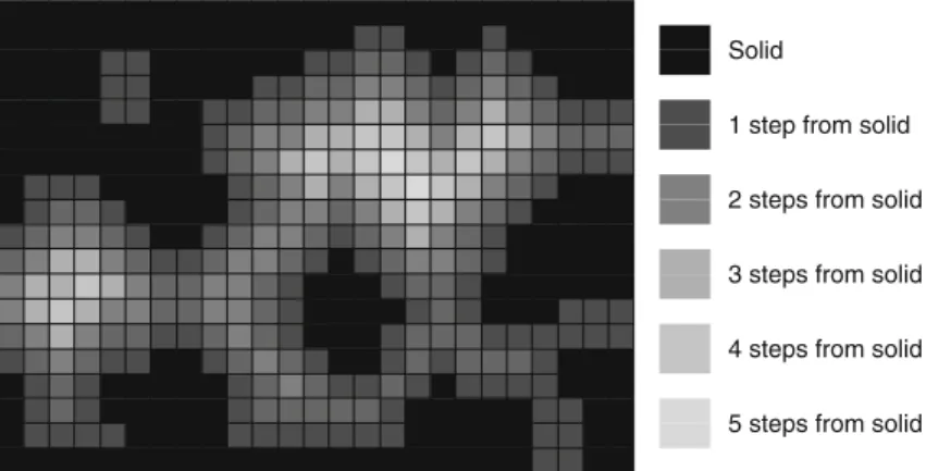
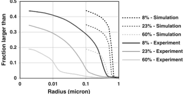
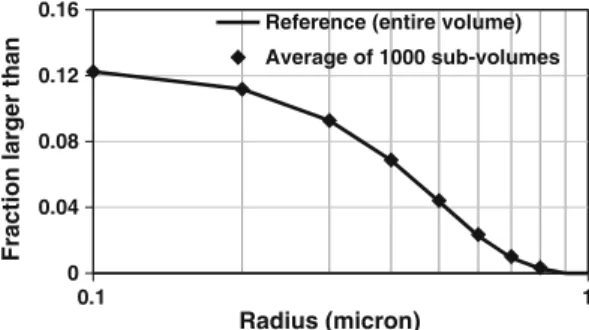
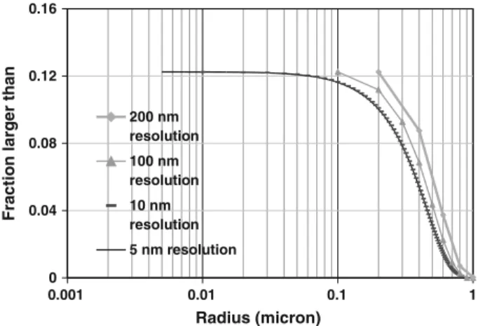
Figure


+7
Documents relatifs