Publisher’s version / Version de l'éditeur:
Vous avez des questions? Nous pouvons vous aider. Pour communiquer directement avec un auteur, consultez la première page de la revue dans laquelle son article a été publié afin de trouver ses coordonnées. Si vous n’arrivez pas à les repérer, communiquez avec nous à [email protected].
Questions? Contact the NRC Publications Archive team at
[email protected]. If you wish to email the authors directly, please see the first page of the publication for their contact information.
https://publications-cnrc.canada.ca/fra/droits
L’accès à ce site Web et l’utilisation de son contenu sont assujettis aux conditions présentées dans le site LISEZ CES CONDITIONS ATTENTIVEMENT AVANT D’UTILISER CE SITE WEB.
Combustion Institute Canadian Section, 2007 Spring Technical Meeting [Proceedings], 2007
READ THESE TERMS AND CONDITIONS CAREFULLY BEFORE USING THIS WEBSITE. https://nrc-publications.canada.ca/eng/copyright
NRC Publications Archive Record / Notice des Archives des publications du CNRC :
https://nrc-publications.canada.ca/eng/view/object/?id=08a63268-872c-4ed7-9c40-8daeed99077f https://publications-cnrc.canada.ca/fra/voir/objet/?id=08a63268-872c-4ed7-9c40-8daeed99077f
Archives des publications du CNRC
This publication could be one of several versions: author’s original, accepted manuscript or the publisher’s version. / La version de cette publication peut être l’une des suivantes : la version prépublication de l’auteur, la version acceptée du manuscrit ou la version de l’éditeur.
Access and use of this website and the material on it are subject to the Terms and Conditions set forth at Mixture fraction gradient effects on heat release in partially premixed combustion
MIXTURE FRACTION GRADIENT EFFECTS ON HEAT RELEASE
IN PARTIALLY PREMIXED COMBUSTION
P.C. Vena1, B. Deschamps1, G.J. Smallwood2, and M.R. Johnson1,*
1
Mechanical & Aerospace Engineering, Carleton University
2
Combustion Group, Institute for Chemical Process & Environmental Tech., NRC
Abstract
The effect of the mixture fraction gradient on a turbulent premixed/non-premixed, rod stabilized, isooctane/air, V-flame was studied. Two-dimensional line spectrometry was performed along a wide spectral range (UV to near IR) to identify radiating species and to characterize each branch of the partially premixed flame (PPF). Chemiluminescence imaging of OH* and CH* was used to estimate time averaged heat release rates. Results are presented and discussed and limitations of these line of sight diagnostics techniques are considered for the current flame configuration. Preliminary OH PLIF images are shown and the design of a proposed experiment for heat release Planar Laser Induced Fluorescence (PLIF) is described.
Introduction
In many next generation low emission/low fuel consumption devices, combustion occurs within a partially premixed turbulent regime in which local fuel concentration fluctuations affect local flame structure, wrinkling, flame thickness, flammability limits, and heat release. Much work has gone into characterizing laminar partially premixed combustion, where focus is most often placed on the structure and propagation velocity of triple flames and the effects of strain, gravity, Lewis number, heat release, and mixture fraction gradient [1-11]. Emphasis has also been placed on their role in the stabilization mechanism for non-premixed axisymmetric flames, where the liftoff characteristics of PPFs are considered [11-12]. Much less is known about turbulent PPF for which the mixture fraction gradient is an explicitly controlled parameter. This paper describes an experimental investigation on partially premixed combustion through the use of a unique burner that enables variation of mixture fraction longitudinally along a flame, replicating conditions that are relevant to practical stratified combustion devices.
Experimental setup
A rectangular exit burner was designed that permits controlled, longitudinal variation of the mixture fraction gradient for local equivalence ratios ranging from 0 to 2 along the long axis of the burner. The mixture fraction gradient and mean flow velocity can be independently controlled using two pairs of fuel and air mass flow controllers. A more detailed description is provided in [13]. In the present experiments, the mean flow velocity was fixed at 5 m/s. A 4 mm wide, 5 m/s air-co-flow surrounds the exit of the burner. The co-flow was deemed necessary after preliminary imaging results showed evidence of secondary mixing and air entrainment which affected combustion in the premixed branches and altered the overall structure of the flame. Experimental settings are typical of those found in industrial applications with a mixing system suitable to gasoline like fuels, relevant to automotive applications.
The current study utilizes an isooctane/air mixture with a single equivalence ratio (φ) gradient with φ ranging from 2 to 0. A 1.5 mm diameter rod placed perpendicularly to the exit nozzle of the burner is used to stabilize the flame in a “V” configuration. The stabilizing rod is positioned at x=29.4 mm from the inner edge on the rich side of the exit nozzle, where φ≈1.07, which for an isooctane air mixture would correspond to a maximum unstrained, laminar flame speed of SLD,MAX ≈ 57 cm/s
[14].
The partially premixed V-flame is composed of two leading premixed branches, one fuel rich and the other fuel lean, that are followed by a trailing diffusion branch as shown in Figure 1. The diffusion tail feeds off the excess fuel and oxidizer from the two premixed flames, which in turn are affected by the mixture fraction gradient.
Time averaged images of local emission intensity of CH* and OH* radical chemiluminescence were captured to obtain an estimate of the mean flame front. Luminescence is collected with a 384x578 gated ICCD equipped with 310 nm and 430 nm (FWHM10 nm) band pass filters for OH* and CH* and a Nikkor 105 mm UV lens. PLIF imaging of OH was also performed using a Sirah Precision Scan Rhodamine B dye laser pumped by a frequency doubled IR beam from a Nd:YAG laser (Quanta Ray PIV 400). OH was excited at 282 nm within a 15 mm high laser sheet. Fluorescense images were captured by an intensified CCD camera (ICCD) equipped with a 310 nm BP filter (FWHM10 nm) mounted on a Nikkor 105 mm UV lens.
Chemiluminescence Spectrometry and Imaging
The PPF was first characterized using an imaging spectrometer configured for vertical line images representing a flame area of 0.1 mm x 100 mm. Each branch of the flame was scanned vertically over a wavelength range of 200 nm to 750 nm with a 600 g/mm grating, 10 µm slit width, and exposure times varying form 2 sec to 60 sec. Within the emission spectrum of the flame, several species were identified, the most prominent being OH* @ 308 nm and 282 nm, CH* @ 431 nm, CN* @ 460 nm and 563 nm, and C2
@ 516 nm. Each of these species were identified from distinct, clearly defined spectral footprints analogous to those simulated by LIFBASE [15]. Continuous fronts of CO2
from approximately 360 nm and soot from 500nm to the end of the scanned range of 750 nm were also apparent. Results were comparable to those of a DICI engine from Ando and Kuwahara [16] .
Comparing the composition of both premixed and diffusion branches, results were as expected with a qualitatively greater CH* concentration in the rich premixed branch than in the lean whereas OH* levels are comparable for both premixed branches. Both CH* and OH* intensities are lower in the diffusion branch. Since the adiabatic flame temperature varies significantly across the PPF (1900 K at φ=0.6 and 2400 K at φ=1.1), corresponding to a significant difference in the emission intensity of the premixed flame
Figure 1: Rod-stabilized V-flame with
a rich to lean mixture fraction gradient from
branches, temperature information within the flame would be required to make quantitative observations.
Chemiluminescence images of OH* and CH* are recorded for heat release approximations in the reaction zone of the two premixed branches and the trailing diffusion branch of the PPF. Luminescence is collected with a 384x578 gated ICCD equipped with 310 nm and 430 nm (FWHM10 nm) bandpass filters for OH* and CH* and a Nikkor 105 mm UV lens. The exposure time was 100 ms, depth of field 5 cm, and F-stop 11. CH* and OH* are strong indicators of the reaction zone [17] and can be correlated to local heat release rate from
(
)
local
local R
I α H α, where the exponent is dependant on flame temperature and unsteady strain and flame curvature [18]
Figure 2 shows time averaged chemiluminescence images of OH* and CH* which are consistent with trends observed with the imaging spectrometer. In both cases, the rich premixed branch had a thicker flame brush than the lean, which could indicate greater fluctuations along the rich flame front.
Figure 2. Chemiluminescence of a)OH* and b)CH* with 310 and 430 FWHM 10nm BP filters (air co-flow, spatial resolution 222µm/pixel)
There is a slight increase in apparent intensity of OH* and CH* in the upper left (rich) branch of the images even though temperature would be reduced in this region relative to lower down in the flame. This suggests the presence of a secondary reaction zone as the excess fuel mixes with the co-flow air farther from the exit nozzle. The flame seems to bend towards ambient air which would correspond with an improved mixture quality and propagation velocity increase.
The principle difference between OH* and CH* images is the emission intensity in the region between both premixed branches. In the case of OH*, a continuous front is present with a greater concentration along the stoichiometric streamline, where the turbulent diffusion branch is most often located. In contrast, the CH* signal is relatively much weaker in this region.
OH* CH*
leaner richer
leaner richer
Integrating the OH* and CH* emission intensities across the premixed flame front, an indication of the mean heat release rate can be obtained at a given location and equivalence ratio. If the mixture fraction gradient profile is assumed to be linear across the longitudinal axis of the burner, maximum heat release is observed at φ≈1.4 for OH* and φ≈1.5 for CH* images. These results do not agree with those found in literature, in which OH* max occurs from φ≈0.9-1.1 and CH* max occurs at φ≈1.1 [18], which would correspond with the equivalence ratios at the location of the stabilization bar. It has been suggested that in regions of high strain rate and flame curvature, the relation between emission intensity and heat release rate may break down [19]. The region of highest strain in the PPF V-flame corresponds to φ≈0.9-1.1 or potentially φ≈0.8-1.2 due to excessive strain in the flame front, which would reduce the effectiveness of this diagnostic in the current flame structure. Furthermore, temperature gradients along both premixed flame fronts vary, which will also affect emission intensity and limit the chemiluminescence results to qualitative importance only.
PLIF Imaging
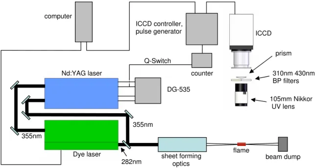
The laser diagnostic setup for simultaneous OH and CH2O PLIF is presented in Figure 3.
The laser system consists of a dual head Nd:YAG laser (Quanta Ray PIV 400) and frequency converter units. The zigzag side IR beam is frequency tripled for an available energy output greater than 300 mJ/pulse @ 355 nm (broadband, 7 ns) and will be used in future work for CH2O excitation. The straight IR beam is frequency doubled to pump a
Rhodamin B dye laser (Sirah Precision Scan). The tunable output from the dye laser (approx 15 mJ per 6 ns pulse @ 282 nm, narrowband) excites OH in the A-X (1,0) band.
Figure 3. Heat Release Rate PLIF Setup
Before performing simultaneous OH and CH2O PLIF, focus was first placed on OH
imaging. OH was excited using a transition near 281.1 nm which is not very sensitive to temperature. The laser beam was formed into a 15 mm x 200 micron sheet which
computer
Nd:YAG laser
Dye laser sheet forming
optics ICCD 105mm Nikkor UV lens DG-535 counter ICCD controller, pulse generator prism 310nm 430nm BP filters Q-Switch flame 355nm 355nm 282nm beam dump
intersected the central plane of the exit nozzle in the interaction region. Laser pulse spectral densities were below saturation levels such that the fluorescence signal was not saturated and emission intensity linearity was ensured. OH fluorescence from the (0,0) and (1,1) bands near 310 nm was captured with an ICCD fitted with a UV f/4.5 Nikkor lens and 310 nm (FWHM10 nm) BP filter. A table top prism can be placed in front of the camera to split the ICCD into two separately filtered regions for simultaneous imaging at two-different wavelengths. To verify that the laser-generated interferences were negligible, the laser was tuned off resonance at which point no signals were observed. The PLIF images were recorded with a projected spatial resolution of 222 µm/pixel, giving a good compromise between resolution, field of view imaging area, and laser sheet thickness.
OH PLIF
Figure 4 shows a set of 10 typical raw images of single pulse cross sections from 50 to 65 mm above the stabilizing rod of the burner. A strong fluorescence signal/noise ratio is observed in the burnt gases as the hydroxyl radicals formed in the reaction zone remain in the region behind the premixed flame front. Also, the interface between signal and non signal area can be used as a marker of the flame front, where drastic differences in curvature and fluctuation frequency are observed when comparing rich and lean premixed fronts. This occurrence seems repeatable and is most likely related to Lewis number differences in the rich and lean premixed branches as well as differences in adiabatic temperature Tad(φ). Observations seem repeatable on all ten images.
Ten sets of single pulse 2D images were collected at different vertical positions in the PPF. Beginning at z = 3 mm above the stabilizing rod, PLIF images were captured at 15 mm intervals that correspond to the 15 mm high laser sheet in order to visualize flame topography from 3 mm to 153 mm. A reconstructed PPF using 3 random but typical images in each set is presented in Figure 6 with an equivalence ratio varying from 2 on the left side to 0 on the right side of the images. This results in a turbulent V-flame burning at varying adiabatic temperatures along both premixed fronts. Given the same longitudinal distance from the stabilization rod, the local laminar burning velocity and the flame front thickness should be comparable. Differences in adiabatic flame temperature and Lewis number should be more significant.
Five distinct regions are identified in Figure 5: 1) flame front directly above the stabilization rod, 2) lean branch from 20 to 80 mm, 3) rich branch from 20 to 80 mm, 4) the rich side from 95 mm and above, and 5) the lean side from 95 mm. The transition zone is in the region 90 to 95 mm above the stabilization rod.
Zone 1: Immediately above the stabilization rod, the PLIF signal is strongest. Because of the proximity of both premixed branches to one another, as well as the highest reaction rate in the PPF, OH concentrations are at a maximum. This region is also the hottest in the image. The two premixed flame fronts are characterized by smooth and positive curvature towards the unburnt mixture while very sharp cusps are observed toward the products. According to diffusive-thermal theory, the reactant temperature on positive fronts (convex toward reactants) increases, leading to larger local velocities than the negative fronts (concave toward reactants), where reactant temperature is lower.
Figure 4. Individual OH PLIF images 50-65 mm above the
stabilizing rod
Figure 5. PPF topology reconstitution with random OH PLIF images recorded at different positions above the stabilizing rod
Zone 2: From 20 to 80 mm, the lean premixed flame shows a smoothly wrinkled front with larger positive curvatures toward the unburnt mixture and still remaining negative curvatures toward the products. Wrinkling length scales are of the same shape as those obtained by Bell et al.[20] for lean premixed propane/air flames where Le>1.
Zone 3: Along the same 20-80 mm height on the rich side, images depict elongated structures extended toward the unburnt mixture that occur at a high wrinkling frequency suggesting thermo-diffusively unstable flame front that are again comparable to those obtained by Bell et al.[20] for lean premixed hydrogen/air flames where Le<1. On some of the images, these structures disappear as the concave fronts merge and form a larger structure. Conversely, the overly-strained elongated structures may result in local extinctions which lead to soot formation and unburnt or partially burnt hydrocarbons. Zone 4: Above 95 mm, on the lean side of the flame front, sharp cusp-like wrinkling toward the unburnt mixture is apparent, unlike all of the other regions in both rich and lean premixed flames. Images also show a fluorescence signal that is homogeneous from the flame front to within the inner region of the PPF, up to what is proposed to be the stoichiometric plane, which could potentially show the evidence of excess oxidizer in the lean flames.
Zone 5: Above 95 mm on the rich side, the fluorescence signal is mostly present in the reaction zone but decreases more rapidly across the product area than does the OH on the lean side. However, at this stage no conclusions can be made since the lack of fluorescence signal behind the rich premixed branch could also be due to a strong absorption of OH fluorescence emission around 308 nm from soot, partially burned
hydrocarbons, or PAHs, etc. as emitted photons traverse the distance between the laser sheet and camera.
It is proposed that the diffusion flame is located along the inner region of the continuous OH front, where the signal begins to fade. Not only is the blurry front typical of diffusion flames, but it also lies along what should be the stoichiometric streamline. Images in sections 4) and 5) show the presence of what are thought to be tube-like structures, shown as empty circles or tracks, with locally high fluorescent intensities along their edges. They are most likely part of the diffusion flame within the mixing layer, which would contain many OH radicals and partially burnt hydrocarbons.
Future Work
Given the limited success in evaluating the heat release rate in a PPF from OH* and CH* chemiluminescence, focus will be placed on obtaining the pixel by pixel product of simultaneous OH and CH2O PLIF images. This serves as a more direct measure of local
heat release rate as OH and CH2O are precursors to HCO from
2 2
CH O + OH→HCO + H O, which has been shown to correlate well with local heat release rate [21]. PLIF is also spatially and temporally resolved, and species selective even at low concentrations, which is better suited to turbulent flames. Local temperature and equivalence ratio measurements will also be set-up from dual excitation of 3-pentanone [22-23]. Correlations will then be made between local heat release, flame front curvature, and equivalence ratio in an effort to further characterize turbulent partially premixed combustion.
References
[1] Kioni P.N., Rogg B., Bray K.N.C, Linan A., Combustion and Flame 95 (1993), 276-290. [2] Santoro V. S., Linan A., Gomez A., Proc. Combust. Inst. 28 (2000), 2039-2046.
[3] Phillips H., Proc. Combust. Inst. 10 (1965), 1277-1283. [4] Dold J. W., Combustion and Flame 76 (1989), 71-88.
[5] Hartley L.J., Dold J. W., Combustion Science Technology 80 (1991), 23-46. [6] Buckmaster J., Matalon M., Proc. Combust. Inst. 22 (1988), 1527-1535. [7] Daou R., Daou J., Dold J., Proc. Combust. Inst. 29 (2002), 1559-1564. [8] Ruetsch G.R., Vervisch L., Linan A., Physics of Fluids 7 (1995), 1447-1454.
[9] Azzoni A., Ratti S., Ishwar K, Puri I. K., Aggarwal S. K., Physics of Fluids 11 (1999), 3449-3464. [10] Guo H., Liu F., Smallwood G.J., International Journal of Thermal Sciences, 45 (2006), 586-594. [11] Lock A., Briones A., Qin X., Aggarwal S., Puri I., Hedge U., Comb. and Flame 143(2005), 159-173. [12] Kim N., Seo J., Oh K., Shin H., Proc. Combust. Inst. 30 (2005), 367-374.
[13] Vena P., Deschamps B., Smallwood G., Johnson M. Comb. Inst. Canadian Section, (2006), G4-1. [14] Gülder, O. L., SAE paper no. 841000, 1984.
[15] Luque, Jorge, LIFBASE, 2007.
[16] Ando H. and Kuwahara, K., SAE Technical Paper Series, 2001-01-0248.
[17] Najm H., Paul P., Mueller C., Wyckoff P., Combustion and Flame 113 (1998), 312-332. [18] Hardalupas et al., First Int. Conf. on Gas Turbine Technologies, Brussels (2003).
[19] Samaniego J., Egolfopoulos F., Bowman C., Combustion Science and Tech. 109 (1995), 183-203. [20] Bell J., Cheng R., Day M., Shephard I., Proc. Combust. Inst. 31 (2007), 1309-1317.
[21] Paul P. and Najm H. , Proc. Combust. Inst. 27 (1998), 43-50.
[22] Schulz, C. and Sick, V., Prog. Energy Combust. Science 31, 75-121 (2005). [23] Einecke, S., Schulz, C. and Sick, V , Appl. Phys. B 71 (5), 717-723 (2000).