Publisher’s version / Version de l'éditeur:
Vous avez des questions? Nous pouvons vous aider. Pour communiquer directement avec un auteur, consultez la
première page de la revue dans laquelle son article a été publié afin de trouver ses coordonnées. Si vous n’arrivez pas à les repérer, communiquez avec nous à PublicationsArchive-ArchivesPublications@nrc-cnrc.gc.ca.
Questions? Contact the NRC Publications Archive team at
PublicationsArchive-ArchivesPublications@nrc-cnrc.gc.ca. If you wish to email the authors directly, please see the first page of the publication for their contact information.
https://publications-cnrc.canada.ca/fra/droits
L’accès à ce site Web et l’utilisation de son contenu sont assujettis aux conditions présentées dans le site LISEZ CES CONDITIONS ATTENTIVEMENT AVANT D’UTILISER CE SITE WEB.
Research Report (National Research Council of Canada. Institute for Research in Construction), 2007-12-01
READ THESE TERMS AND CONDITIONS CAREFULLY BEFORE USING THIS WEBSITE.
https://nrc-publications.canada.ca/eng/copyright
NRC Publications Archive Record / Notice des Archives des publications du CNRC : https://nrc-publications.canada.ca/eng/view/object/?id=fe66e778-845d-4346-8deb-ef00b03b87cb https://publications-cnrc.canada.ca/fra/voir/objet/?id=fe66e778-845d-4346-8deb-ef00b03b87cb
NRC Publications Archive
Archives des publications du CNRC
For the publisher’s version, please access the DOI link below./ Pour consulter la version de l’éditeur, utilisez le lien DOI ci-dessous.
https://doi.org/10.4224/20378007
Access and use of this website and the material on it are subject to the Terms and Conditions set forth at
Automated assembly of microsystems start up and shut down procedures
http://irc.nrc-cnrc.gc.ca
A u t o m a t e d A s s e m b l y o f M i c r o s y s t e m s S t a r t
U p a n d S h u t D o w n P r o c e d u r e s
R R - 2 4 5
W o n g , B .
D e c e m b e r 2 0 0 7
The material in this document is covered by the provisions of the Copyright Act, by Canadian laws, policies, regulations and international agreements. Such provisions serve to identify the information source and, in specific instances, to prohibit reproduction of materials without written permission. For more information visit http://laws.justice.gc.ca/en/showtdm/cs/C-42
Les renseignements dans ce document sont protégés par la Loi sur le droit d'auteur, par les lois, les politiques et les règlements du Canada et des accords internationaux. Ces dispositions permettent d'identifier la source de l'information et, dans certains cas, d'interdire la copie de documents sans permission écrite. Pour obtenir de plus amples renseignements : http://lois.justice.gc.ca/fr/showtdm/cs/C-42
TABLE OF CONTENTS
List of Tables ……… ii
List of Figures ……… iii
Preface ……… v
IMPORTANT! PLEASE READ THIS FIRST ……… v
1.0 Introduction ……… 1
2.0 Start Up Procedure ……… 2
3.0 Shut Down Procedure ……… 21
4.0 Controller Software User Interface ……… 31
4.1 NView HMI - IO Page - Analog ……… 32
4.2 NView HMI - IO Page - Digital ……… 33
Appendix A Electrical Connection ……… 34
A.1 Inside Front Panel Electrical Connection ……… 35
A.2 Inside Front Panel Label Assignment ……… 36
A.3 Inside Front Panel - 2TB - 1SC - Integrated Power Supply and Switching Circuit for Gassmann Engineering WPT6-106 & WPT6-107 Circuit Diagram ……… 38
A.4 Rear Panel - 4TB - Breakout Blocks JM1BB and JM2BB Electrical Connection ……… 39
A.5 Breakout Block JM1BB Assignment ……… 40
A.6 Breakout Block JM2BB Assignment ……… 41
Appendix B Electrical Connection Photographs ……… 42
B.1 Festo Vacuum System ……… 43
B.2 Module JM2 ……… 44
B.3 Inside Front Panel - 1TB to 4TB ……… 45
B.4 Inside Front Panel - 1TB - 1PS, 2PS, 3PS, 4PS, Terminal Block(LNG) ……… 46
B.5 Inside Front Panel - 2TB - 1SC, 1PEC, Terminal Block(20) … 47 B.6 Rear Panel - 1TB to 4TB ……… 48
B.7 Rear Panel - 1TB ……… 49
B.8 Rear Panel - 2TB - DC 24V, 5A ……… 50
B.9 Rear Panel - 4TB - Breakout Blocks J9BB, J10BB, JM2BB & JM1BB and Module JM1 ……… 51
LIST OF TABLES
Table Page
1 Inside Front Panel Label Assignment ……… 36
2 Breakout Block JM1BB Assignment (for Module JM1) ……… 40
3 Breakout Block JM2BB Assignment (for Module JM2) ……… 41
LIST OF FIGURES
Figure Page
1 Automated Assembly of Microsystems - AREA CLEAR ……… 2
2 Compressed Air for Granite Table Base - ON ……… 3
3 Compressed Air for Aerotech Stages - ON ……… 4
4 Compressed Air for Festo Vacuum System - ON ……… 5
5 Power Cable (Hubbell Plug) - Coming Out Bottom Left of Console …… 6
6 Power Supply for 120V AC 20A ……… 7
7 Lower Panel Door Latch - OPEN ……… 8
8 Lower Panel Door - OPEN ……… 9
9 APC Uninterruptible Power Supply - ON ……… 10
10 Main Power Supply Switch - ON ……… 11
11 Front Panel POWER ON Light ON - POWER ON ……… 12
12 Lower Panel Door Latch - OPEN ……… 13
13 Lower Panel Door - OPEN ……… 14
14 A3200 Npaq Green Switch Light - ON ……… 15
15 Front Panel RESET Light OFF - RESET ……… 16
16 Chassis Plans Panel Door - OPEN ……… 17
17 Chassis Plans Panel POWER - ON ……… 18
18 Chassis Plans Panel Door - CLOSE ……… 19
19 Log On to Windows - OK ……… 20
20 Automated Assembly of Microsystems - AREA CLEAR ……… 21
21 Log On to Windows - Shut Down... ……… 22
22 Front Panel POWER ON Light OFF - POWER OFF ……… 23
23 Main Power Supply Switch - OFF ……… 24
24 Lower Panel Door Latch - OPEN ……… 25
25 Lower Panel Door - OPEN ……… 26
26 APC Uninterruptible Power Supply - OFF ……… 27
27 Compressed Air for Festo Vacuum System - OFF ……… 28
28 Compressed Air for Aerotech Stages - OFF ……… 29
29 Compressed Air for Granite Table Base - OFF ……… 30
30 NView HMI - IO Page - Analog ……… 32
31 NView HMI - IO Page - Digital ……… 33
32 Inside Front Panel Electrical Connection ……… 35
33 Inside Front Panel - 2TB - 1SC - Integrated Power Supply and Switching Circuit for Gassmann Engineering WPT6-106 & WPT6-107 Circuit Diagram ……… 38
34 Rear Panel - 4TB - Breakout Blocks JM1BB and JM2BB Electrical Connection ……… 39
35 Festo Vacuum System ……… 43
36 Module JM2 ……… 44
37 Inside Front Panel - 1TB to 4TB ……… 45
38 Inside Front Panel - 1TB - 1PS, 2PS, 3PS, 4PS, Terminal Block(LNG) 46
39 Inside Front Panel - 2TB - 1SC, 1PEC, Terminal Block(20) ……… 47
40 Rear Panel - 1TB to 4TB ……… 48
41 Rear Panel - 1TB ……… 49
42 Rear Panel - 2TB - DC 24V, 5A ……… 50 43 Rear Panel - 4TB - Breakout Blocks J9BB, J10BB, JM2BB & JM1BB
and Module JM1 ……… 51
PREFACE
Automated Assembly of Microsystems Project
The Automated Assembly of Microsystems Project at the National Research Council of Canada (NRC) started around June 2005. Team members included Shafee Ahamed, Vibhor Gupta, Dave Kingston (Retired July 2007), Ajit Pardasani, Alfred Sham (Left September 2006) and Brian Wong. Guest workers included Christophe Fauchreau (August-December 2007) and Pierre-Nicolas Porcin-Raux (August 2006 - May 2007). For further assistance, please contact Mr. Ajit Pardasani, Project Leader, as follows:
Address: 800 Collip Circle, London ON N6G 4X8
Phone: (519) 430-7085
Email: ajit.pardasani@nrc-cnrc.gc.ca
Automated Assembly of Microsystems Start Up and Shut Down Procedures
To provide feedback on the content of this document, please contact Mr. Brian Wong as follows:
Address: 800 Collip Circle, London ON N6G 4X8
Phone: (519) 430-7083
Email: brian.wong@nrc-cnrc.gc.ca
December 2007 (Version 3, RR-245) December 2006 (Version 2, IMTI-TR-036) June 2006 (Version 1, Laboratory)
IMPORTANT! PLEASE READ THIS FIRST
The Automated Assembly of Microsystems Start Up and Shut Down Procedures are still in their preliminary stage of development and are provided as is. Assumptions were made that users of the equipment have general knowledge of the computing, electrical, mechanical and software systems. Please follow the instructions with caution.
1.0 Introduction
The Automated Assembly of Microsystems Project makes use of a variety of precision devices such as stages and manipulator, with integrated compressed air, computer, vacuum and vision systems, etc. to assist the user in developing a generic platform for micro-assembly automation.
This document will guide the user through sets of figure-by-figure with step-by-step instructions to perform proper equipment start up and shut down procedures.
2.0 Start Up Procedure
Step 1:
Check that all cables, parts and tubing are securely fastened [Fig. 1]. Do the same for all the connecting devices in Appendix B.
Note: Due to the nature of this high precision equipment, the motion system will require calibration or tuning whenever a related part of the device has been modified or
relocated. And to minimize vibration, external stimuli should be avoided when the equipment is in operation.
Step 2:
Ensure the working area is clear for the motion system to be energized [Fig. 1].
Figure 1. Automated Assembly of Microsystems - AREA CLEAR
Step 3:
Turn on the compressed air (Blue Lever) for the granite table base as shown in Figure 2. It might take some time for the pressures in the system to be stabilized.
Note: If any pressure gauge shows a zero reading, please correct the situation before continuing to the next step.
Figure 2. Compressed Air for Granite Table Base - ON
Step 4:
Turn on the compressed air (Blue Lever) for the Aerotech stages as shown in Figure 3. It might take some time for the pressures in the system to be stabilized.
Figure 3. Compressed Air for Aerotech Stages - ON
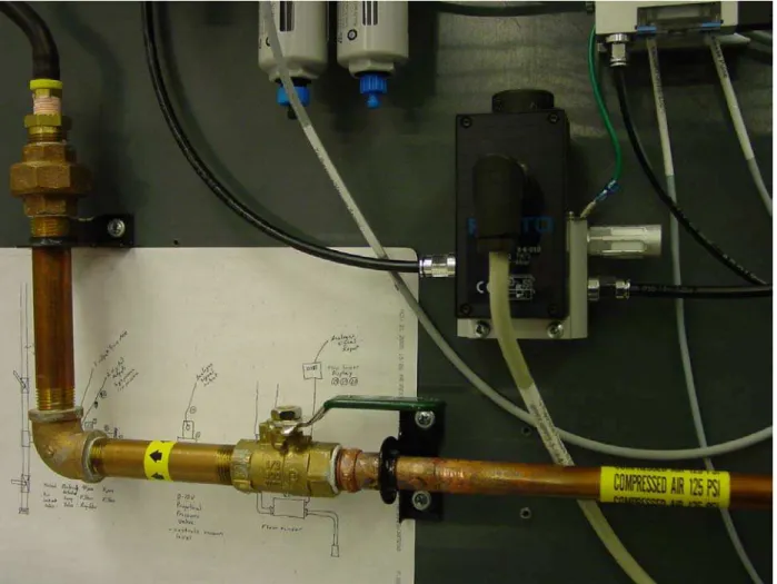
Step 5:
Turn on the compressed air (Green Lever) for the Festo vacuum system as shown in Figure 4. It might take some time for the pressures in the system to be stabilized. EMC Specifications
With reference and extracted from the Manual “FESTO Operating instructions for the Proportional pressure regulator type MPPES-...” “Make sure that high-frequency interference sources (e.g. walkie-talkies, hand telephones or other non-suppressed devices) are kept at a safe distance from the MPPES-...” “In this way you can avoid increased tolerances of the output pressure...”
Figure 4. Compressed Air for Festo Vacuum System - ON
Step 6:
Locate the black power cable (with the Hubbell Plug) coming out of the bottom left of the console as shown in Figure 5.
Figure 5. Power Cable (Hubbell Plug) - Coming Out Bottom Left of Console
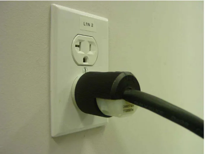
Step 7:
Insert the Hubbell Plug into one of the NEMA 5-20R sockets labelled “L1N 2” if needed for the 120V AC 20A Power Supply as shown in Figure 6.
Figure 6. Power Supply for 120V AC 20A
Step 8:
Turn the lower panel door latch clockwise as shown in Figure 7.
Figure 7. Lower Panel Door Latch - OPEN
Step 9:
Open the lower panel door as shown in Figure 8.
Figure 8. Lower Panel Door - OPEN
Step 10:
Press the (I) or (Test) button to switch on the APC Uninterruptible Power Supply as shown in Figure 9. According to APC, the battery charges to 90% capacity during the first four hours of normal operation. Close the lower panel door if needed.
Figure 9. APC Uninterruptible Power Supply - ON
Step 11:
Turn on the main power supply switch on the back of the controller computer cabinet as shown in Figure 10.
Figure 10. Main Power Supply Switch - ON
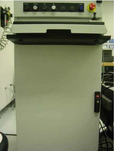
Step 12:
Press on the front panel POWER ON button and the POWER ON light should turn on as shown in Figure 11. The RESET light could be either on or off at this time.
Figure 11. Front Panel POWER ON Light ON - POWER ON
Step 13:
Turn the lower panel door latch clockwise as shown in Figure 12.
Figure 12. Lower Panel Door Latch - OPEN
Step 14:
Open the lower panel door as shown in Figure 13.
Figure 13. Lower Panel Door - OPEN
Step 15:
Check that both the A3200 Npaq Green Switch and the Green Switch light are ON [Fig. 14]. If this is not the case, put the switch in its ON position and the light should turn on as shown in Figure 14.
Figure 14. A3200 Npaq Green Switch Light - ON
Step 16:
If the front panel RESET light is still on, press the RESET button to have it turned off as shown in Figure 15.
Figure 15. Front Panel RESET Light OFF - RESET
Step 17:
Open the Chassis Plans panel door as shown in Figure 16.
Figure 16. Chassis Plans Panel Door - OPEN
Step 18:
Press on the Chassis Plans panel POWER button to turn on the controller computer as shown in Figure 17. It might take some time for the controller computer to be booted up.
Figure 17. Chassis Plans Panel POWER - ON
Step 19:
Close the Chassis Plans panel door as shown in Figure 18 if there is no immediate need for the other devices on the controller computer.
Figure 18. Chassis Plans Panel Door - CLOSE
Step 20:
Once the controller computer is booted up, choose “OK” to start using the controller software as shown in Figure 19.
Figure 19. Log On to Windows - OK
3.0 Shut Down Procedure
Step 1:
Check that all cables, parts and tubing are securely fastened [Fig. 20, 35 & 36]. Step 2:
Ensure the working area is clear for the motion system to be de-energized [Fig. 20].
Figure 20. Automated Assembly of Microsystems - AREA CLEAR
Step 3:
Choose “Shut Down...” to shut down the controller computer as shown in Figure 21. It might take some time for the computer to be shut down. Please ensure this step is finished before going to the next step.
Figure 21. Log On to Windows - Shut Down...
Step 4:
Press on the front panel POWER OFF button and the POWER ON light should turn off as shown in Figure 22.
Figure 22. Front Panel POWER ON Light OFF - POWER OFF
Step 5:
Turn off the main power supply switch on the back of the controller computer cabinet as shown in Figure 23.
Figure 23. Main Power Supply Switch - OFF
Step 6:
Turn the lower panel door latch clockwise as shown in Figure 24.
Figure 24. Lower Panel Door Latch - OPEN
Step 7:
Open the lower panel door as shown in Figure 25.
Figure 25. Lower Panel Door - OPEN
Step 8:
Press the (O) button to switch off the APC Uninterruptible Power Supply as shown in Figure 26. Close the lower panel door and remove the Hubbell Plug from one of the NEMA 5-20R sockets labelled “L1N 2” [Fig. 6] if needed.
Note: For as long as the Hubbell Plug is inserted into one of the NEMA 5-20R sockets labelled “L1N 2”, there is power (120V AC 20A) supply to the APC Uninterruptible Power Supply Unit (Smart-UPS 2200).
Figure 26. APC Uninterruptible Power Supply - OFF
Step 9:
Turn off the compressed air (Green Lever) for the Festo vacuum system as shown in Figure 27. It might take some time for the compressed air to be exhausted.
Figure 27. Compressed Air for Festo Vacuum System - OFF
Step 10:
Turn off the compressed air (Blue Lever) for the Aerotech stages as shown in Figure 28. It might take some time for the compressed air to be exhausted.
Figure 28. Compressed Air for Aerotech Stages - OFF
Step 11:
Turn off the compressed air (Blue Lever) for the granite table base as shown in Figure 29. It might take some time for the compressed air to be exhausted and this is the last step of the shut down procedure.
Figure 29. Compressed Air for Granite Table Base - OFF
4.0 Controller Software User Interface
The following sections describe the user interfaces of the integrated devices.
Assumptions were made that the users are familiar with the Aerotech, Inc.’s Automation 3200 (A3200) controller software system.
4.1 NView HMI - IO Page - Analog
The interface “NView HMI - IO Page - Analog” as shown in Figure 30 is configured to display the signal conditions of the following two devices:
1. AEROTECH MFO [Fig. 22]
The MFO function is programmed internally to control the regulated pressure coming out of the FESTO Proportional Pressure Regulator MPPES when the FESTO On-off Valve HEE [Fig. 31] is switched on.
Possible Range on Display: 0 to 10 V
Linear Mapping Range: 0 to 6 bar
2. FESTO Flow Sensor SFEV-R (3 V = 0 l/min)
Possible Range on Display: 1 to 5 V
Linear Mapping Range: -10 to +10 l/min
Figure 30. NView HMI - IO Page - Analog
4.2 NView HMI - IO Page - Digital
The interface “NView HMI - IO Page - Digital” as shown in Figure 31 is configured to display the sensors status information (Drive Inputs) and to control the switches (Drive Outputs) of the respected devices.
Notes:
1. Never switch on the FESTO Vac. Generator VADMI Vacuum Generation and Release Pulse at the same time.
2. Please observe the warnings and the operating instructions of the respected devices.
Figure 31. NView HMI - IO Page - Digital
Appendix A Electrical Connection
A.1 Inside Front Panel Electrical Connection
Please refer to the instruction manuals of the individual devices for the mounting spaces requirement.
Rear Panel - 1TB Rear Panel 4TB -Breakout Block J9BB PULNiX AccuPiXEL TMC-1325CL (Horizontal) Gassmann Engineering WPT6-106 PULNiX AccuPiXEL TMC-1325CL (Vertical) Gassmann Engineering WPT6-107 Zaber Technologies T-CD2500 (Horizontal) Zaber Technologies T-CD2500 (Vertical) NAVITAR MOTOR DRIVER MODEL # 1-62420 (Horizontal) NAVITAR MOTOR DRIVER MODEL # 1-62420 (Vertical)
Frame Ground
Figure 32. Inside Front Panel Electrical Connection
A.2 Inside Front Panel Label Assignment
Table 1. Inside Front Panel Label Assignment
Label Device/Terminal Description Serial No./Part No.
1PS OMRON S8VM-01505CD
POWER SUPPLY
INPUT: AC100-240V 50/60Hz 0.5A OUTPUT: DC5V 3A
HFP 4OW-721Y29-0019W4406
2PS OMRON S8VM-01505CD
POWER SUPPLY
INPUT: AC100-240V 50/60Hz 0.5A OUTPUT: DC5V 3A
HFP 4OW-703Y29-0023W2406
3PS OMRON S8VM-05012CD
POWER SUPPLY
INPUT: AC100-240V 50/60Hz 0.8A OUTPUT: DC12V 4.3A
HFP 4P5-721Y32-0099W4206
4PS OMRON S8VM-10024CD
POWER SUPPLY
INPUT: AC100-240V 50/60Hz 1.4A OUTPUT: DC24V 4.5A
HFP 4PB-712Y52-0298W3706
L AC115V 15A Live Phoenix Contact 3004524 w/
0203263 w/ 1052002
N AC115V 15A Neutral Phoenix Contact 3004524 w/
0203263 w/ 1052002 1TB
AC115V 15A Ground Phoenix Contact 0442079 w/
1052002
1SC Integrated Power Supply and Switching
Circuit for Gassmann Engineering WPT6-106 & WPT6-107
Please refer to the circuit diagram in Appendix A.3.
1PEC Protective Earthing Connection Keystone Electronics Corp 1006
1 +
for Gassmann Engineering WPT6-106 2 -
for Gassmann Engineering WPT6-106 3 +
for Gassmann Engineering WPT6-107 4 -
for Gassmann Engineering WPT6-107
5 For Future Expansion
6 For Future Expansion
7 +V (of 2PS)
8 For Future Expansion
9 For Future Expansion
2TB
10 -V (of 2PS)
Phoenix Contact 3004362 w/ 1051003
11 +12V
for PULNiX AccuPiXEL TMC-1325CL S/N: 000078 (Horizontal)
S/N: 000081 (Vertical) 12 +
for Zaber Technologies T-CD2500 Ser. No. 11893 (Horizontal) 13 +
for Zaber Technologies T-CD2500 Ser. No. 11894 (Vertical)
Phoenix Contact 3004362 w/ 0203250 w/ 1051003
14 GND (power)
for PULNiX AccuPiXEL TMC-1325CL S/N: 000078 (Horizontal)
S/N: 000081 (Vertical) 15 -
for Zaber Technologies T-CD2500 Ser. No. 11893 (Horizontal) 16 -
for Zaber Technologies T-CD2500 Ser. No. 11894 (Vertical)
Phoenix Contact 3004362 w/ 0203250 w/ 1051003
17 +
for NAVITAR MOTOR DRIVER MODEL # 1-62420
S/N 405170 (Horizontal) 18 +
for NAVITAR MOTOR DRIVER MODEL # 1-62420
S/N 405173 (Vertical)
Phoenix Contact 3004362 w/ 0203250 w/ 1051003
19 -
for NAVITAR MOTOR DRIVER MODEL # 1-62420
S/N 405170 (Horizontal) 20 -
for NAVITAR MOTOR DRIVER MODEL # 1-62420
S/N 405173 (Vertical)
Phoenix Contact 3004362 w/ 0203250 w/ 1051003
3TB Not Connected For Future Expansion N/A
4TB ⊥ Panel Ground N/A
38
A.3 Inside Front Panel - 2TB - 1SC - Integrated Power Supply and Switching Circuit for Gassmann Engineering WPT6-106 & WPT6-107 Circuit Diagram
The circuits with terminals (1 to 4) and (11 to 14) are two precision current regulators each providing 380mA with the two potentiometers (R1) each set at 3.6Ω approximately. The circuitry with terminals (5 to 7) and (8 to 10) consists of two switching circuits for controlling the Gassmann Engineering WPT6-106 and WPT6-107 respectively.
Figure 33. Inside Front Panel - 2TB - 1SC - Integrated Power Supply and Switching Circuit for Gassmann Engineering WPT6-106 & WPT6-107 Circuit Diagram
10 9 8 11 12 13 14 1 2 3 4 5 6 7 In Out Adj LM317 In Out Adj LM317 D1 R1 R2 D1 D1 D1 HS1 HS1 R1 R2 T1 T1 KEY D1 1N4001 HS1 576802B00000G
(Aavid Thermalloy Heat Sink) R1 43P100 (10Ω)
R2 1.5KΩ
T1 2N4400
Terminal Assignment
1 5V DC (Supply Voltage)
2 Connected to Terminal 7 Externally* 3 - for WPT6-106
4 + for WPT6-106
5 0V (of 5V DC)
6 Switch Input for WPT6-106 (On = 24V DC) (Off = 0V DC) 7 Connected to Terminal 2 Externally*
8 0V (of Switch Input)
9 Switch Input for WPT6-107 (On = 24V DC) (Off = 0V DC) 10 Connected to Terminal 12 Externally*
11 5V DC (Supply Voltage)
12 Connected to Terminal 10 Externally* 13 - for WPT6-107
14 + for WPT6-107 Note:
39
A.4 Rear Panel - 4TB - Breakout Blocks JM1BB and JM2BB Electrical Connection
Please refer to 4/03/06 AEROTECH, INC. Filename 136397 E15723-207.DWG for Breakout Blocks J9BB and J10BB Existing Electrical Connection.
DC 24V, 5A Inside Front Panel - 2TB - 1SC
+ - 6 9 J9BB 13 ⊥ 12 25 11 24 10 23 9 22 8 21 7 20 6 19 5 18 4 17 3 16 2 15 1 14 J10BB 8 ⊥ 7 15 6 14 5 13 4 12 3 11 2 10 1 9 JM2BB 8 ⊥ 7 15 6 14 5 13 4 12 3 11 2 10 1 9 JM1BB 13 ⊥ 12 25 11 24 10 23 9 22 8 21 7 20 6 19 5 18 4 17 3 16 2 15 1 14
Figure 34. Rear Panel - 4TB - Breakout Blocks JM1BB and JM2BB Electrical Connection 10K 10K 10K 10K 10K 10K 10K 10K
A.5 Breakout Block JM1BB Assignment
Table 2. Breakout Block JM1BB Assignment (for Module JM1) Label Description Part No. Pin Cable
Colours
Cable Description
1 2 Black Switch Input
(On = 24 V DC) (Off = 0 V DC) 0V (for Switch Input Pin 1 Setting) 2 1 Black 0 V (for Switch Input Pin 2 Setting) Switch Input (On = 24 V DC) (Off = 0 V DC) 3
FESTO On-off Valve HEE, D Series (HEE-D-MINI-24) w/ FESTO Plug Socket with Cable KMEB (KMEB-1-24-5-LED)
172956 w/ 151689
⊥ Green/Yellow Ground
4 1 Brown + 24 V DC Supply Voltage
5 2 White Output B 6 3 Blue 0 V 7 FESTO Pressure/Vacuum Sensor (SDE1-D10-G2-R18-C-P2-M8) w/ FESTO Plug Socket with Cable SIM (SIM-M8-4GD-5-PU)
192027 w/ 158961
4 Black Output A
8 2 Brown Ground (of Win)
9 3 Green Ground (of 24 V DC)
10 4 Yellow Win (Setpoint Value Input, 0-10 V
DC)
11 6 Pink Xout (Actual Value Output)
12 7 Red 24 V DC (Supply Voltage)
13
FESTO Proportional Pressure Regulator MPPES (MPPES-3-1/8-6-010) w/ FESTO Plug Socket with Cable KMPPE (KMPPE-B-5)
187352 w/ 161878
8 Blue Ground (of Xout)
14 1 Brown +
15 3 Blue -
16
FESTO Vacuum
Generator (VADMI-70) w/ FESTO Plug Socket with Cable KMYZ-2 (KMYZ-2-24-M8-0.5-LED) & FESTO Plug Socket with Cable SIM (SIM-M8-3GD-5-PU) 162507 w/ 177676 & 159421
4 Black Switch Input (Vacuum
Generation) 17 1 Brown + 18 3 Blue - 19 FESTO Vacuum Generator (VADMI-70) w/ FESTO Plug Socket with Cable KMYZ-2 (KMYZ-2-24-M8-0.5-LED) & FESTO Plug Socket with Cable SIM (SIM-M8-3GD-5-PU) 162507 w/ 177676 & 159421
4 Black Switch Input (Release Pulse)
20 21 22 23 24 25 ⊥
Not Connected N/A N/A
A.6 Breakout Block JM2BB Assignment
Table 3. Breakout Block JM2BB Assignment (for Module JM2) Label Description Part No. Pin Cable
Colours Cable Description 1 2 3 4 5 6 7 8 9 10
Not Connected N/A N/A
11 N/A Brown 12-24 V DC (Supply Voltage)
12 N/A Blue 0 V (Ground)
13 N/A Grey Analog Output (1-5 V)
14 N/A Black OUT1
15
FESTO Miniature Flow Sensor SFEV-R Series (SFEV-R1000-L-2PD-K1) w/ FESTO Miniature Flow Sensor SFET-R Series (SFET-R1000-L-WQ4-D-K3)
538555 w/ 538539
N/A White OUT2
⊥ FESTO Proportional Pressure Regulator MPPES (MPPES-3-1/8-6-010) 187352 ⊥∗ Dark Green (User Defined) Earth (Ground)
* Housing of the FESTO Proportional Pressure Regulator MPPES.
Appendix B
Electrical Connection Photographs
B.1 Festo Vacuum System
The Festo Vacuum System as shown in Figure 35 includes electrical control, sensors and switching components, namely:
A. On-off Valve HEE, D Series B. Pressure/Vacuum Sensor SDE1
C. Proportional Pressure Regulator MPPES
D. Vacuum Generator VADMI Vacuum Generation E. Vacuum Generator VADMI Release Pulse F. Miniature Flow Sensor SFEV-R Series G. Miniature Flow Sensor SFET-R Series
A B F D E G C
Figure 35. Festo Vacuum System
B.2 Module JM2
The Module JM2 [Fig. 36] is part of the Festo Vacuum System [Fig. 35].
Figure 36. Module JM2
B.3 Inside Front Panel - 1TB to 4TB
The inside front panel is accessible through the upper front panel door of the controller computer cabinet and is located behind the two-screw lockable, hinged, LCD support frame structure.
Figure 37. Inside Front Panel - 1TB to 4TB
B.4 Inside Front Panel - 1TB - 1PS, 2PS, 3PS, 4PS, Terminal Block(LNG)
Figure 38. Inside Front Panel - 1TB - 1PS, 2PS, 3PS, 4PS, Terminal Block(LNG)
B.5 Inside Front Panel - 2TB - 1SC, 1PEC, Terminal Block(20)
Figure 39. Inside Front Panel - 2TB - 1SC, 1PEC, Terminal Block(20)
B.6 Rear Panel - 1TB to 4TB
The rear panel is accessible through the rear panel door of the controller computer cabinet. Please refer to 4/03/06 AEROTECH, INC. Filename 136397 E15723-204.DWG for the original rear panel assembly details.
Figure 40. Rear Panel - 1TB to 4TB
B.7 Rear Panel - 1TB
Figure 41. Rear Panel - 1TB
B.8 Rear Panel - 2TB - DC 24V, 5A
Figure 42. Rear Panel - 2TB - DC 24V, 5A
51
B.9 Rear Panel - 4TB - Breakout Blocks J9BB, J10BB, JM2BB & JM1BB and Module JM1
Figure 43. Rear Panel - 4TB - Breakout Blocks J9BB, J10BB, JM2BB & JM1BB and Module JM1