Publisher’s version / Version de l'éditeur:
Vous avez des questions? Nous pouvons vous aider. Pour communiquer directement avec un auteur, consultez la
première page de la revue dans laquelle son article a été publié afin de trouver ses coordonnées. Si vous n’arrivez pas à les repérer, communiquez avec nous à PublicationsArchive-ArchivesPublications@nrc-cnrc.gc.ca.
Questions? Contact the NRC Publications Archive team at
PublicationsArchive-ArchivesPublications@nrc-cnrc.gc.ca. If you wish to email the authors directly, please see the first page of the publication for their contact information.
https://publications-cnrc.canada.ca/fra/droits
L’accès à ce site Web et l’utilisation de son contenu sont assujettis aux conditions présentées dans le site LISEZ CES CONDITIONS ATTENTIVEMENT AVANT D’UTILISER CE SITE WEB.
ACEEE Summer Study on Energy Efficiency in Buildings 2006, American Council for an Energy Efficient Economy [Proceedings], pp. 1-13-24, 2006-08-01
READ THESE TERMS AND CONDITIONS CAREFULLY BEFORE USING THIS WEBSITE.
https://nrc-publications.canada.ca/eng/copyright
NRC Publications Archive Record / Notice des Archives des publications du CNRC :
https://nrc-publications.canada.ca/eng/view/object/?id=cb628c5d-8cdc-44c2-b27d-165a24f7d820 https://publications-cnrc.canada.ca/fra/voir/objet/?id=cb628c5d-8cdc-44c2-b27d-165a24f7d820
NRC Publications Archive
Archives des publications du CNRC
This publication could be one of several versions: author’s original, accepted manuscript or the publisher’s version. / La version de cette publication peut être l’une des suivantes : la version prépublication de l’auteur, la version acceptée du manuscrit ou la version de l’éditeur.
Access and use of this website and the material on it are subject to the Terms and Conditions set forth at Testing a residential fuel cell for combined heat and power
Bell, M.; Swinton, M. C.; Manning, M. M.; Entchev, E.; Gusdorf, J.; Szadkowski, F.
Canadian Centre
Centre canadien des
for Housing Technology
technologies résidentielles
Testing a residential fuel cell for combined heat and power
Bell, M.; Swinton, M.C.; Manning, M.M.; Entchev, E.; Gusdorf, J.; Szadkowski, F.
NRCC-49220
A version of this document is published in / Une version de ce document se trouve dans:
ACEEE Summer Study on Energy Efficiency in Buildings 2006, American Council for an Energy Efficient Economy, Pacific, Grove, CA., U.S.A. August-13-06, pp. 1-13-24, August-01-06
The Canadian Centre for Housing Technology (CCHT)
Built in 1998, the Canadian Centre for Housing Technology (CCHT) is jointly operated by the National Research Council, Natural Resources Canada, and Canada Mortgage and Housing Corporation. CCHT's mission is to accelerate the development of new technologies and their acceptance in the marketplace.
The Canadian Centre for Housing Technology features twin research houses to evaluate the whole-house performance of new technologies in side-by-side testing. The twin houses offer an intensively monitored real-world environment with simulated occupancy to assess the performance of the residential energy technologies in secure premises. This facility was designed to provide a stepping-stone for manufacturers and developers to test innovative technologies prior to full field trials in occupied houses.
As well, CCHT has an information centre, the InfoCentre, which features a showroom, high-tech meeting room, and the CMHC award winning FlexHouse™ design, shown at CCHT as a demo home. The InfoCentre also features functioning state-of-the art equipment, and demo solar photovoltaic panels. There are over 50 meetings and tours at CCHT annually, with presentations and visits occurring with national and international visitors on a regular basis.
Testing a Residential Fuel Cell for Combined Heat and Power
Mike Bell, Innovative Energy SystemsMike Swinton and Marianne Manning, National Research Council Canada Evgueniy Entchev, John Gusdorf and Frank Szadkowski, Natural Resources Canada
ABSTRACT
The first fuel cell (FC) in a residential application in Canada was tested at the Canadian Centre for Housing Technology (CCHT). A 5kW second-generation solid oxide fuel cell manufactured in Canada was run for 1587 hours during the late winter and spring of 2005. Modifications to one of the CCHT houses allowed heat from the FC to be used for space heat and hot water, and electricity to be sent to and from the grid. This project demonstrated the performance of a residential FC combined heat and power (CHP) system, and examined residential CHP integration issues such as thermal storage, grid connection, and optimal FC size.
Data collection included the FC’s natural gas use and outputs of electricity and heat, electricity to and from the grid, heat to space heat and hot water, and supplementary heat (natural gas) required. The efficiency with which the FC generated electricity (DC & AC) and heat were measured, and found to agree with the manufacturer’s specifications.
The average measured efficiencies of the fuel cell, in terms of the lower heating value (LHV) of natural gas, are: DC electrical: 46.6%, AC electrical: 24.7%, and thermal: 27.6%. Combining AC and thermal yields an overall efficiency of 52.3%.
Introduction
Residential combined heat and power (CHP) systems have several potential advantages over centralized electricity generation. By generating electricity in or near a residence, a CHP system makes it possible to capture the waste heat and use it for space heat and hot water, thus significantly reducing fuel use. Applied on a large scale, CHP systems can result in distributed generation, which can reduce line losses, and reduce or eliminate the need for new power plants and transmission lines. Widespread application of residential CHP systems requires both the development of the core technologies and their integration into buildings. A CHP device produces heat and electricity simultaneously, and there will be times when the building requires one but not the other. There are a large number of issues that need to be resolved in order to properly integrate a CHP system into a residential building such as: optimal sizing and control of the CHP system, meeting peak loads (both electrical and thermal), need for and sizing of thermal storage, standardized technique for grid connection and the ability to export electricity, emergency power operation during grid outages, safety, and standards and code issues (Bell et al. 2004; Davis et al. 2005; Gunes & Ellis 2003; Massie, Boettner & Massie 2005).
Natural Resources Canada (NRCan) has an initiative to assess the performance of small CHP systems as they emerge from the manufacturers’ laboratories, and to test ways of integrating them into residential buildings. NRCan has formed partnerships with a number of leading Canadian gas and electric utilities, research organizations, universities, manufacturers and other government agencies. This initiative has been carried out primarily at the Canadian Centre for Housing Technology (CCHT), which provides an intensively monitored residential
environment with simulated occupancy to assess the performance of residential CHP systems in secure premises.
The CCHT is operated as a partnership of three agencies of the Canadian government (NRCan, Canada Mortgage and Housing Corporation, and National Research Council Canada). The facility consists of two identical R-2000 test houses and a three-unit townhouse. The test houses are highly instrumented with approximately 230 points of temperature, RH, airflow and moisture content, plus 28 kWh meters, 10 water meters, and 4 natural gas meters. Key data is saved every five minutes, and all data is saved hourly. The houses have a programmable simulated occupancy system that controls loads such as the stove, clothes washer and dryer, dishwasher, lights, and hot and cold water draws. Heat produced by four occupants is simulated by banks of light bulbs operated in different parts of the house on a daily schedule.
The CCHT provides an ideal stepping stone between lab tests of residential CHP systems and field trials in occupied housing. It provides a real house installation and energy demand, realistic, repeatable simulated occupancy, intensive monitoring, easy access to equipment, and a secure site. The CHP system was installed in on of the CCHT’s two houses in Ottawa, Canada, a location with 4673 heating degree-days (base 18 °C), and a design heating temperature of -24 ° C (-13 °F). The house has a volume of 789 m3 (27,860 ft3), and a design heat loss of 12.9 kW (44,000 Btu/h). The daily hot water use is 242 L (64 US gal) at 55 °C (131 °F).
Project Objectives
The CHP fuel cell was installed at the CCHT in order to:
• Demonstrate the installation of the first residential fuel cell CHP system in a house in Canada;
• demonstrate the performance of the fuel cell CHP system in the residence during different seasons; and
• examine CHP-house integration issues such as HVAC interface, control strategies, grid connection, ability to deal with peak and partial thermal and electrical loads, need for/benefit of thermal storage, amount of electrical export, and optimal fuel cell CHP size.
The CHP System
The Fuel CellA fuel cell CHP system was tested at the CCHT in a joint project with its manufacturer, a Canadian developer of small solid oxide fuel cells (SOFC) intended for the residential and small commercial market. Development of the second-generation product had reached a stage where installation and testing in an actual house would be beneficial. The SOFC system operates on natural gas and uses tubular solid oxide technology. It has a nominal output of 5 kilo-watts of electricity (kWe), and includes a grid-tied inverter. It is water-cooled through an internal heat exchanger.
This second-generation system featured important improvements from earlier installations, including gas-powered warm-up to allow the unit to be started without an additional electrical power source; the ability to use lower natural gas pressures; and the use of a methanol
purge instead of an expensive purge gas mixture. In addition, the inverter was redesigned to satisfy residential standards. The system also featured improved control of the output power.
The fuel cell uses natural gas supplied at 15.17 kPa (2.2 psig), lower than previous models, but still higher than the standard 3.45 kPa (0.5 psig) supplied to residential appliances. The natural gas is reformed internally, and hydrogen rich reformate gas is supplied to the stack at the correct temperature. As with all fuel cells, the stack produces direct current (DC) electricity which is used to charge the batteries and run the controls and balance of plant. The batteries power the controls and balance of plant during start-up, can supply peak loads in stand-alone systems, and can absorb electrical power during shut-downs due to grid power failures. The controls are programmed for seamless ramping up to operating conditions, maintaining a desired output in normal operation, and ramping-down during shut-down. They provide the stack with optimal conditions during all stages of operation, so as to maximize the stack lifetime. Power vented reaction products are cooled to about 50 °C (120 °F), and can be side vented.
Figure 1. Schematic Diagram of the Fuel Cell Thermal Utilization Module
The Thermal Utilization Module (TUM)
The thermal utilization module is shown in Figure 1. It was designed to capture the medium grade heat from the fuel cell’s internal cooling system, and to use it for space heat and domestic hot water as required. In planning for this residential fuel cell CHP system, research into similar installations indicated that two others were in the planning stages, but the participants were not willing to share design information. For this reason, the design of the TUM
is based on the CCHT’s previous work with a Stirling engine CHP system (Bell et al. 2004) in consultation with the manufacturer.
Basic design parameters indicated that fuel cell would not be able to supply the peak thermal loads of the house, so the TUM included a back-up heater in the form of the burner in the hot water tank. At other times, the house would not be able to use all of the fuel cell’s thermal output, so a means of dissipating heat was required. Normally, this would be done by using a by-pass damper to direct heat around the fuel cell’s internal heat exchanger. However, we wanted to capture and measure this excess heat since it has potential uses such as absorption cooling. For this reason, the TUM included a heat dissipation loop that automatically sent excess heat to the outside when storage was full. The TUM had the following main components:
• the primary and backup pumps that ensured continuous circulation of cooling water through the fuel cell’s internal heat exchanger;
• a 3-way valve that directed the cooling water either to storage or dissipation; • the hot water tank (HWT) used as the storage tank and backup heater; • the air handler (AH) that supplied space heat to the house;
• the double-wall, external heat exchanger (HX) that transfers heat from the cooling water to the glycol in the heat dissipation loop; and
• a second air handler (Heat Dissipation) through which outdoor air was blown to dissipate heat.
The TUM also included a solenoid and check valve to achieve correct flow through whichever of the pumps was operating, two mixing valves to deliver water to hot water and space heat at consistent temperatures, and a glycol reservoir with pressurized expansion tank in the heat dissipation loop.
The 285 L (75 US gal) HWT and the AH were already installed as a combination space heat and hot water system for the previous CHP experiment. This combo system supplied space heat to the house whenever it was demanded by the house thermostat, and hot water whenever it was demanded by the simulated occupancy system. The HWT aquastat operated in the normal way, supplying backup heat when required. When the HWT could no longer take heat from the fuel cell at an acceptable temperature, then the 3-way valve directed the cooling water to the external heat exchanger. At the same time, the pump and fan in the heat dissipation air handler were turned on, pumping glycol through the heat dissipation loop, and blowing outside air through the dissipation air handler and then back outside.
The Electrical System
Figure 2 is a schematic of the electrical equipment and wiring used to connect the fuel cell to the house and the grid, and to monitor power transferred among them. Most of these modifications had already been done for a previous CHP system, including the installation of:
• three bi-directional, pulse-generating kilowatt-hour meters (M1, M2 and M4); • a four-pole transfer switch to allow three operating configurations, and
• a 200 amp disconnect / isolating switch with fuses to protect and isolate the CHP system being tested.
Figure 2. Schematic Diagram of the Wiring for the Fuel Cell
The three operating configurations are: 1. Normal house operation (no CHP system installed or working), 2. CHP system operation in grid-tie mode, and 3. CHP system in stand-alone mode. The major change that was made specifically for the fuel cell was the addition of the “pony panel”. The pony panel is connected directly to the AC output of the fuel cell, and powers devices that would be required to keep the fuel cell working in the event of a grid power failure. These include:
• the dissipation air handler in the garage;
• the primary and secondary coolant pumps, and the Xantech relays that control them; • the 3-way valve that switches the TUM between heat storage and dissipation mode; • a 24 volt power supply for the 3-way valve; and
• two electrical heaters that would dissipate the fuel cell’s electrical output during a shut-down due to a power failure.
Methodology
This project involved preparation of the fuel cell, modifications to the CCHT, monitoring and control of the fuel cell and the equipment for using its thermal energy, and data analysis and presentation.
Fuel Cell Preparation, Ownership & Control
The manufacturer tested the fuel cell at their own facilities before delivery to CCHT. The unit operated there continuously and without problems for 640 hours. The manufacturer maintained ownership and control of the unit at all times, and specified that it would be operated as closely as possible to a steady-state condition which would maximize the lifetime of the stack.
Preparations at the CCHT
Modifications to the CCHT test house included the installation of equipment outside the house to meter natural gas and supply it at the required pressure, physical modifications to the garage to accommodate the fuel cell, electrical modifications to connect the fuel cell to the house and grid, modifications and additions to the thermal utilization module (TUM) used in a previous CHP system test, and the installation and programming of monitoring, control and alarm systems.
Controls
The fuel cell controls are internal and proprietary, and they are not discussed in this report. The TUM was controlled by the same data logger that collected data on its performance. The main function of this control was to switch between heat storage and dissipation. The TUM began operation in heat storage mode, in which the fuel cell cooling water went to the HWT. The TUM was switched to heat dissipation mode when any of the following conditions were met:
• the temperature of the water leaving the fuel cell was >70 °C (158 °F); • the water entering the HWT was >69 °C (156 °F); or
• the water at the top of the HWT was >68 °C (154 °F).
The TUM was switched back to heat storage mode when both of the following conditions were met:
• the water at the bottom of the HWT was <40 °C (104 °F); and • the water leaving the fuel cell was <65 °C (149 °F).
The maximum temperature of cooling water leaving the fuel cell was specified by the manufacturer. The conditions for switching from dissipation to storage were selected to avoid dissipating more heat than necessary while not switching between modes excessively. In the event of a primary pump failure, the TUM control would detect the lack of coolant water flow, and: 1. turn on the backup pump, 2. open the normally closed solenoid that allowed water to
flow through the backup pump, and 3. activate an automatic telephone to notify NRCan staff. If the backup pump had been turned on, and the control had then detected a lack of cooling water flow, it would have activated the automatic telephone to make further calls. A third set of calls would have been made if the TUM were in heat dissipation mode and a lack of flow had been detected in the glycol loop.
Data Collection
Three separate data collection system were used during the fuel cell testing: • the fuel cell’s internal monitoring system;
• the CCHT’s main data collection system; and • the TUM’s dedicated data logger.
The internal monitoring system. The fuel cell’s internal control system collected a large
number of data points including natural gas use by the burner and the stack, the stack and battery voltage and current, air flows and temperatures, stack temperatures, and flue gas and water temperatures in and out of the internal heat exchanger. These data were sent over the internet to the manufacturer at least once per minute, and more often when a potential problem was detected. Some of this data are proprietary, but some were shared with the project and are analyzed below.
The CCHT’s main data collection system. As mentioned, large amounts of data are routinely
collected in the CCHT houses. Of this data, the output of three kWh meters (M2, M3 and M4 in Figure 2), two of which are bi-directional (M2 and M4) were used to analyze the fuel cell’s performance.
The dedicated data logger. A Campbell CR23X was used to scan 26 points every ten seconds
and record them every minute. As shown in Figure 1, these points include 18 temperatures, four liquid flows, the relative humidity of air entering the fuel cell, the volume of natural gas used by the fuel cell and by the HWT, and the pressure of natural gas entering the fuel cell. Temperature differences and liquid flows were used to determine the following heat flows: 1. heat out of the fuel cell; 2. heat entering the HWT; 3. heat dissipated; 4. heat to space heat; and 5. heat to domestic hot water.
Data Analysis
Data was analyzed to determine the fuel cell’s efficiency, which can be defined in several ways. First, the energy content of the natural gas used by the fuel cell can be specified according to either the lower heating value (LHV) or the higher heating value (HHV). For natural gas delivered during the fuel cell testing the LHV was 33.88 MJ/m3 (909.3 Btu/ft3), and the HHV was 37.41 MJ/m3 (1004 Btu/ft3). The HHV is used for rating gas appliances in North America, while the LHV is used in Europe and in the fuel cell industry, so all efficiencies are defined in both ways. The fuel cell’s electrical efficiency can be defined in terms of the DC output of the stack, or the AC output of the entire unit. The fuel cell’s thermal efficiency is defined in terms
of the heat extracted in the cooling water. The fuel cell’s overall efficiency is the sum of its electrical and thermal energy. Thus, there are eight definitions of fuel cell efficiency:
• DC electrical efficiency, LHV: Stack DC output divided by LHV of the natural gas used; • DC electrical efficiency, HHV: Stack DC output divided by HHV of the natural gas used; • AC electrical efficiency, LHV: Fuel cell AC output divided by LHV of natural gas used; • AC electrical efficiency, HHV: Fuel cell AC output divided by HHV of natural gas used; • Thermal efficiency, LHV: Fuel cell heat output divided by LHV of natural gas used; • Thermal efficiency, HHV: Fuel cell heat output divided by HHV of natural gas used; • Overall efficiency, LHV: AC electrical efficiency, LHV plus thermal efficiency, LHV. • Overall efficiency, HHV: AC electrical efficiency, HHV plus thermal efficiency, HHV.
Each of these efficiencies is important. LHV or HHV must be specified in order to make comparisons with other devices on an equal basis. DC electricity is the output of the stack itself, while the AC output also depends on the particular inverter used, but AC electricity is the useful output of the fuel cell. Data was also analyzed to determine DC to AC conversion efficiency, and to show what amounts of the fuel cell’s electricity were used by the house and sent to the grid, and how much grid electricity was required under different condition. The fuel cell’s thermal output was compared with the house’s demands, and the amount of backup heat required.
Results
The fuel cell was delivered to the CCHT on 28 February 2005. It was activated on 3 March, and continued to warm up until 1:15 am on 6 March when it began to generate electricity and automatically connected to the grid. The plan was to operate the fuel cell continuously until July, but the loss of critical internal thermocouples caused the manufacturer to decide to shut it down on 12 May 2005.
Use of Fuel Cell Electricity
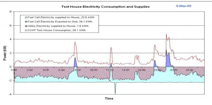
Figure 3 shows the electrical power generated by the fuel cell, used by the house, and supplied from or sent to the grid during a cold winter day (9 March 2005, min: -18.6 °C (-1 °F), mean -13.4 °C (8 °F)). Negative values indicate generation by the fuel cell, and exports to the grid. Positive values represent consumption by the house, and use of grid electricity. Thus, the four dark areas corresponding to peaks in house demand represent times when the fuel cell does not meet the house electrical demands, and grid electricity is used. Numbers in the legend are the daily totals in kWh. The house draws electricity from the grid only during four peak periods, each less than an hour in duration. The peaks are due mainly to the use of the stove. The maximum power draw from the grid is 2.5 kW, compared with the maximum house demand of 4.8 kW. The fuel cell supplies 93% of the 24.1 kWh used by the house, and exports 31.4 kWh to the grid.
Figure 3. Electricity Profiles for a Cold Winter Day
Figure 4. Electricity Profiles for a Hot Summer Day
Graphs of mild winter and spring days show basically the same pattern as Figure 3, but as Figure 4 shows, the situation on a hot summer day (13 June 2005, max 29.4 °C (85 °F), mean 26.9 °C (80 °F)) with significant air conditioner use would be quite different. Figure 4 is based on actual house consumption for that day, and fuel cell electrical output from typical spring days. (Output was higher in spring than in winter because the manufacturer had increased it slowly as the fuel cell continued to operate normally). The air conditioner’s frequent and high demands cause the fuel cell to supply a smaller percentage of the house electrical consumption, and to send less electricity to the grid. Electricity from the grid is needed during 24 periods, one of
which is over three hours long. The maximum demand from the grid is 3.5 kW, compared with the maximum house demand of 6.2 kW. The fuel cell supplies 90.5 % of the 52.6 kWh used by the house, and exports 18.7 kWh to the grid. These results indicate that on any given day, the fuel cell should reduce peak demand by at least 40%, and should supply net energy to the grid.
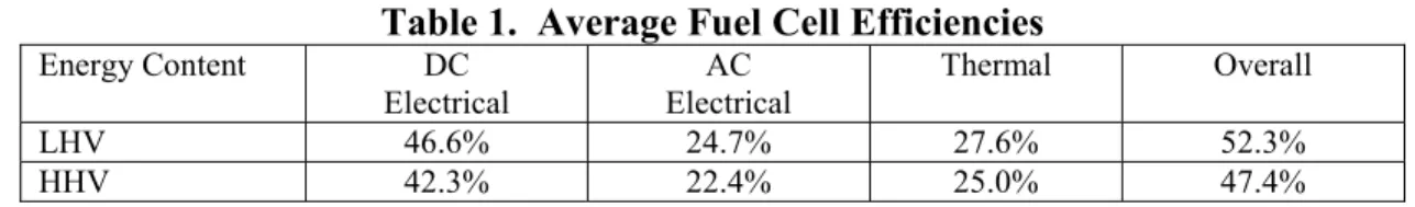
Fuel Cell Efficiency
Table 1 shows the measured fuel cell efficiencies as defined above. It should be noted that the DC electrical efficiencies are based on the manufacturer’s data on DC power from the stack, while all other values are based on the CCHT’s independent measurements of natural gas use, fuel cell AC electrical output, and thermal output. The measured efficiencies agree with the manufactures specification, and the AC efficiency is in the 20 to 30% range reported for other residential fuel cell demonstrations (Davis et al. 2005). On average 55.8% of the DC energy is converted to AC. When the approximately 600 W DC that is used internally is taken into account, the average efficiency of the fuel cell’s inverter appears to be 65.5%. This is considered low, and the manufacturer plans to replace the inverter in future units.
Table 1. Average Fuel Cell Efficiencies
Energy Content DC Electrical AC Electrical Thermal Overall LHV 46.6% 24.7% 27.6% 52.3% HHV 42.3% 22.4% 25.0% 47.4%
Overall is the sum of AC Electrical and Thermal.
Thermal Storage & Backup Heat
The fuel cell’s average thermal output of just over 2 kW is often not enough to supply the house space heat and hot water loads during winter, especially when losses between the fuel cell and the tank and from the tank are included. For example, Table 2 shows the fuel cell output and hot water tank inputs and outputs for the winter days with the largest and smallest space heat and hot water demands. For March 9 & 10, the total house demand was just over twice the fuel cell output, and the hot water tank burned a large amount of natural gas for backup heat. For March 19 & 20, the total demand was less than the fuel cell output, but a significant amount of backup heat was still required to make up for losses.
Figure 5 shows that thermal storage would be required even when total demand and losses are smaller than the fuel cell output, as would be the case during the shoulder and summer seasons. The fuel cell’s nearly constant 2 kW thermal output is small in comparison with the demand for space heat (4 to 6 kW) and hot water (up to 16.9 kW). Thus, the thermal storage in the hot water tank serves as a buffer between the smaller, constant output of the fuel cell, and the larger, intermittent demands for space heat and hot water.
Table 2. Fuel Cell Output and House Thermal Demands (kWh)
Interval Fuel Cell Output Space Heat Hot Water Total Demand HWT Gas March 9 & 10 96.79 184.47 11.52 195.99 218.39 March 19 & 20 96.38 70.08 15.39 85.49 68.18
Figure 5. Thermal Profile from a Cold Winter Day
Summary of Fuel Cell Performance
The fuel cell was tested during 1614 hours (67.25 days) from March 6 to May 12, 2005. It used natural gas and produced heat for 1,587 hours, or 98% of the time, and it produced electricity for 1,467 hours, or 91% of the time. Table 3 shows the amounts of electricity and heat it generated, and the uses of the electricity. Note that the average values include three periods during which the fuel cell was shut down and had to be restarted and ramped up. This included a period of five days with no electrical generation.
Table 3. Summary of Fuel Cell Outputs
Fuel Cell Output Total (kWh) Average (kW) % of FC Elec.
Electric Fuel Cell 3072 2.09 100% Net System 2804 1.91 91% Used by House 867 0.59 28% To Grid 1937 1.32 63% Thermal 4046 2.55 122%
Discussion & Conclusions
This project clearly demonstrated that it is possible to install and operate a solid oxide fuel cell in a house, and to generate most of the electrical needs of the house, while reducing peak demands and exporting significant amounts of electricity to the grid. The project also demonstrated that it is possible to capture and store heat from the fuel cell and use it effectively to supply some or all of the space and water heating loads of the house under a broad range of conditions. Thermal storage was shown to be an essential component of the thermal utilization
module, even when supply of heat from the fuel cell exceeds demand by the house over the day. Mismatches still occur instantaneously, and these need to be evened out by the storage. A considerable amount of excess heat is often available, especially during the summer. Use for this excess heat, including absorption air conditioning should be investigated.
Extensive planning and consultation with the manufacturer paid off, as the fuel cell arrived to an essentially “plug and play” facility. The fuel cell was operating within three days of delivery, and was transmitting surplus power to the grid within six days. All three objectives of the project were met. The installation of the first residential fuel cell CHP system in a house in Canada was demonstrated; the performance of the fuel cell CHP system was quantified during different seasons; and CHP-house integration issues were explored, including HVAC interface, control strategies, grid connection, role of thermal storage, and the amount of electrical export.
This project, and the previous CCHT test of a CHP system (Bell et al. 2004), both show that combo systems work well for storing and using thermal energy in residential systems. Combos are compatible with the forced air heating systems found in most Canadian houses, provide for thermal storage, and supply automatic backup heat when required. Items that would be changed based on the experience of this project include details of the plumbing that produced large transients in the thermal output during hot water draws and changes from heat storage to dissipation, and the use of another bi-directional kWh meter between the fuel cell and the pony panel (Figure 2) to measure the gross AC output of the fuel cell.
Acknowledgements
The project team wishes to acknowledge the participation of Fuel Cell Technologies Ltd (FCT) of Kingston, Ontario. FCT was the developer and owner of the fuel cell tested in this project, which they loaned to the CCHT for residential testing.
References
Bell, M., M. Swinton, E. Entchev, J. Gusdorf, W. Kalbfleisch, R. Marchand, and F.Szadkowsk. 2004. “Testing Residential Combined Heat and Power Systems at the Canadian Centre for Housing Technology.” In Proceedings of the ACEEE 2004 Sumer Study on Energy Efficiency in Buildings, 11:1-12. Washington, D.C.: American Council for an Energy-Efficient Economy.
Davis, M.W., A.H. Fanney, M.J. LaBarre, K.R. Henderson, B.P. Doughery. 2005. “Parameters Affecting the Performance of a Residential-scale Stationary Fuel Cell System.” In Proceedings of Fuel Cell 2005, 197-205. Ypsilanti, Mich.: American Society of Mechanical Engineers.
Gunes, M.M., Ellis M.W. 2003. “Evaluation of Energy, Environmental, and Economic Characteristics of Fuel Cell Combined Heat and Power Systems for Residential Applications.” Journal of Energy Resources Technology, 125:208-220.
Massie, D., D. Boettner, C. Massie. “Residential Experience with Proton Exchange Membrane Fuel Cell Systems for Combined heat and Power.” Journal of Fuel Cell Science and Technology, 2:263-267.