Ternary polymer blend with core–shell dispersed phases: effect of the
core-forming polymer on phase morphology and mechanical properties
I. Luzinov1, C. Pagnoulle and R. Jérôme
Center for Education and Research on Macromolecules (CERM), University of Liège, Institute of Chemistry, B6 Sart-Tilman, 4000 Liège, Belgium
Abstract
Phase morphology and mechanical properties of ternary blends consisting of PS (polystyrene), SBR (styrene butadiene rubber) and different polyolefins (POs) have been studied. PS, systematically forms the matrix, SBR and PO being combined in the dispersed phase. Although POs of various melt viscosity and stiffness are used, the binary (SBR/PO) dispersed phase is of a core–shell structure, in which PO forms the core. Upon increasing the viscosity of PO, the average size of the cores and the SBR domains including them increases. Comparison of the experimental shear storage modulus of the blends with theoretical predictions indicates that the stress transfer from the PS matrix to the PO core through the SBR shell depends on the modulus of the SBR envelope. The ultimate mechanical properties of the ternary blends are sensitive to the stiffness of the PO core.
Keywords: Polymer blend; Phase morphology; Core–shell morphology
1. Introduction
Multiphase polymer blends which contain more than one minor phase deserve a special interest when the general strategy of producing new materials from existing (co)polymers and recycling waste plastics is concerned [1-6]. One of the major targets is then to understand and to control the phase morphology of these multicomponent blends and ultimately their mechanical properties. In this respect, the interfacial tensions between the individual phases and their relative viscosities are two predominant factors. In binary blends, the size of the minor phase depends on the interfacial tension and the viscosity (or torque) ratio of the dispersed phase with respect to the matrix [7-9]. The interplay of these factors although more complex in ternary blends remains essential for the control of the blend morphology, in which each component, is either separately dispersed, or forms a core–shell structure (one minor component forming shell around small domains of the second one) or an intermediate phase organization [1-4]. The equilibrium phase structure being the one with the lowest interfacial free energy, the tendency for one minor phase to encapsulate the second minor component in ternary blends can be predicted by Eq. (1) [1]:
λ31=γ12−γ32−γ13
3
where γ12, γ32 and γ13 are the interfacial tension for each component pair, and λ31 is the spreading coefficient for
the shell forming component 3 with respect to the core forming component 1. The index 2 refers to the matrix. λ31 must be positive for 1 to be encapsulated by 3.
In a previous communication [10], the morphology of polystyrene/styrene butadiene rubber/low density
polyethylene (PS/SBR/LDPE) ternary blends has been investigated in relation to the weight ratio of the SBR and LDPE minor components which are dispersed in the PS matrix. In agreement with λ31, a core–shell structure has
been observed for the dispersed phase, LDPE forming systematically cores in the SBR phase. Two SBR samples of different melt viscosity and surface energy were used, so allowing the size of the dispersed phases and the ultimate mechanical properties to be controlled at least in some limits of blend composition. This paper aims at reporting on the phase morphology and mechanical properties of ternary blends consisting of PS, SBR and polyolefins (POs) of different characteristic features, SBR and PO being combined in the dispersed phase and the PS/SBR/PO ratio being kept constant. Since all the POs used have quite comparable surface energy [11], the previously observed PO/SBR core–shell structure is expected to be maintained. Thus essentially melt viscosity and stiffness of PO will be changed and their effect on the phase morphology and the mechanical properties of the ternary blends will be studied. It must be pointed out that only a few studies have focused until now, on the role played by the melt viscosity on the phase morphology of ternary blends. It has been reported [2-3] that a low viscosity ratio between the engulfing phase and the engulfed one is favorable to the development of the expected core–shell morphology, although an exceedingly high viscosity of the engulfed phase might have a detrimental effect. Finally, almost no data is available in the scientific literature about the effect of the stiffness of the core forming polymer on the mechanical properties of ternary blends with "core–shell" dispersed phases.
2. Experimental 2.1. Materials
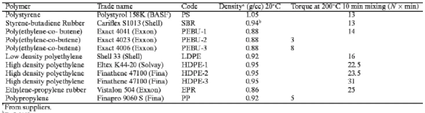
All the blends investigated in this study contained 75 wt% PS, 17 wt% SBR (containing 42.7 wt% styrene) and 8 wt% PO. Representative properties of these constitutive polymers are listed in Table 1.
Table 1. Main characteristics of the polymers used
2.2. Preparation and properties of polyblends
Polymers were blended in a Brabender internal mixer (50 ml) under dry nitrogen at 200°C. They were previously dry-blended and then melt-blended at 200°C for 2 min in the Brabender chamber at 20 rpm, and finally 10 min at 60 rpm (one-step mixing). In order to avoid oxidation reactions, 0.4 wt% antioxidant (Irganox 1010 Ciba Geigy) was added to the preblend. After blending, the melt was rapidly cooled down in ice water.
Phase morphology was observed with a Philips CM 100 transmission electron microscope. A Reichert Jung Ultracut FC 4 microtome equipped with a diamond knife was used to prepare ultrathin sections (70–90 nm thick) from the blends at −100°C. These sections were stained by the sequential exposure to vapors of osmium
tetroxide (30 min) and ruthenium tetroxide (2 h). PS was observed as a dark gray phase, SBR as a black one and the PE phase was light gray.
The average number of PO particles encapsulated in one SBR domain was calculated as the ratio K, between the number of PO droplets and the number of rubbery domains in which they were dispersed.
The size of the PO droplets and the SBR dispersed phases was analyzed by using the KS-100 (Kontron Imaging System) software. The apparent number-average diameter (dn) of these particulate phases was calculated from
the analysis of several areas of the sample, more than 300 particles being scanned per probed area. Because of the non-spherical shape of the dispersed phases, the reported diameters were only apparent values [12]. The thickness of the SBR shell around the PO particles was calculated by Eq. (2) [10]:
a=0.5(dn(rub)/K 0.5
−dn(core)) (2)
where dn(rub) and dn(core) are the number average diameter of the PO containing SBR phase and the PO core,
respectively. K is the average number of PO particles per SBR phase.
The shear storage and loss moduli were measured with a DuPont DMA (model 983) at 1 Hz and the heating rate of 2.5°C min−1. Each value was the average of 2–3 independent measurements.
Tensile and impact test specimens (DIN 53488) were machined from sheets compression molded at 200°C for 5 min and quenched under low pressure.
Stress–strain curves were recorded at room temperature with an Instron tester (model DY24) at 20 mm/min. The Charpy impact strength was measured at room temperature with a CEAST Fractoscope using notched specimens (DIN 53453; 0.3 mm notch). Each tensile or impact value was the average of four to eight independent
measurements.
3. Results and discussion 3.1. Morphology
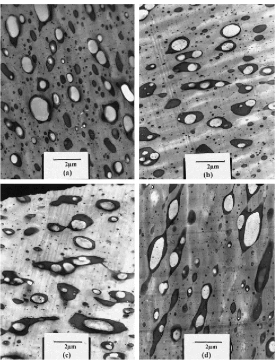
TEM observations confirm that the PS/SBR/PO blends have a core–shell morphology, whatever the PO used. The PO phase is systematically encapsulated by SBR, as shown by TEM images for some blends consisting of different types of core-forming POs (Fig. 1). Thus, small change in the surface tension of PO does not
expectedly change the positive sign of the spreading coefficient calculated for the PS/SBR/LDPE system [10]. As a rule, the average number of polyolefinic subphases per SBR dispersed phase is very close to 1 when calculated by image analysis. Further, the substantial modification of the melt viscosity of the core-forming polymer (see torque values in Table 1) has no effect on the development of the core–shell morphology.
Fig. 1. TEM micrographs for PS/SBR/PO blends consisting of different POs: (a) PEBU-3; (b)LDPE; (c)HDPE-1; (d)EPR.
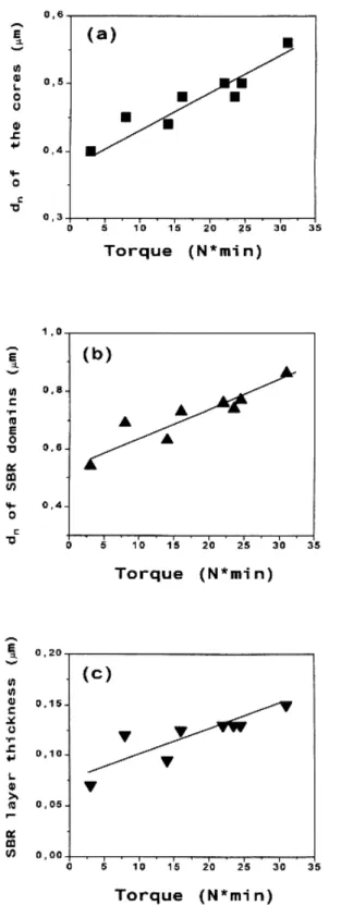
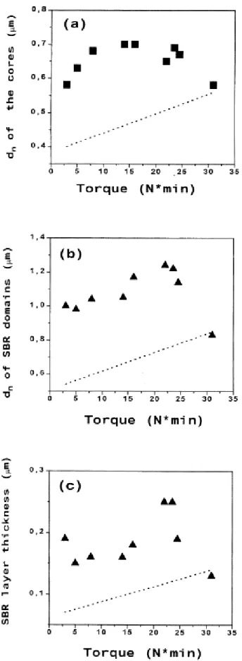
The number average diameter of the PO subphases in the dispersed rubbery phase have been plotted versus the torque of the PO used in this study (Fig. 2a). Clearly, the size of the PO particles increases with the torque of this component measured at 200°C. Favis and Chalifoux have reported on the well-defined dependence of the phase size on the torque ratio for binary polymer blends [7]. Upon decreasing the torque ratio of the minor phase with respect to the major one down to ca. 0.25, the average size of the dispersed phase decreases. The experimental observations for the blends prepared in this study support the validity of this conclusion when extended to ternary blends with core–shell dispersed phases.
Fig. 2. Effect of the PO torque on the number average diameter of the PO cores (a), the SBR domains (b) and the thickness of the SBR layer (c).
The number average diameter of the SBR domains also depends on the torque of the PO cores as shown in Fig. 2b. The SBR domains become larger as the melt viscosity of the core-forming polymer is increased. Therefore, there is a parallel increase of the average size of the SBR phases and the PO subphases. Nevertheless, these modifications do not compensate mutually, so that the thickness of the rubber layer around the PO particles also increases with the PO melt viscosity as illustrated by Fig. 2c.
In order to study the mechanical properties, the ternary blends were compression molded into plates from which the testing specimens were cut out. Since the phase morphology could change upon this thermal treatment, new
TEM observations have been reported (Fig. 3 and Fig. 4) which confirm that the core–shell morphology of the dispersed phase is maintained in all the blends. However, the average number of PO cores per SBR domains (K) has changed at least in some of them. Fig. 5 shows that K, which was 1 before molding, lies between 1.08 and 1.22 after this treatment, except for the ternary blend which contains the highly viscous HDPE-3 polyolefin.
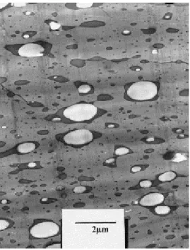
Fig. 3. TEM micrographs for PS/SBR/PO blends after compression molding, PO being: (a) PEBU-3; (b) LDPE; (c) HDPE-1; (d) EPR.
Fig. 4. TEM micrographs for PS/SBR/PP blends after compression molding.
Fig. 6. Number average diameter of the PO core (a) and the SBR domain (b) and thickness of the SBR layer (c) versus the PO torque for compression molded blends. Dotted lines indicate the diameters and thickness before compression molding.
Fig. 6a shows how the diameter of the PO particles has changed upon molding in relation to the torque of the core-forming polymer. This size actually passes through a maximum. The same general behavior is observed for the diameter of the SBR domains (Fig. 6b) and the thickness of the rubbery layer around the PO subphases. As a rule, all these sizes have increased as result of the melt pressing, more likely because of phase coarsening by coalescence [4 ; 13-15]. It has been shown recently that the coalescence of core–shell domains is a two-step process, i.e. coalescence of the encapsulating shell (step 1) followed by coalescence of the core-forming material (step 2) [4], which can account for the main characteristic features of Fig. 6. As a rule the coalescence rate increases, as the viscosity of the dispersed phase is decreased [14 ; 16]. Therefore, when PO with the highest torque is used, the rate of the second step is slow enough for dn of the PO core to remain unchanged after static
annealing (Fig. 6a). The viscosity of the core–shell domains is also expected to depend on the torque of PO and to increase with it, so explaining that the effect of annealing on the average size of the SBR domains (step 1) decreases sharply at high PO torque ( Fig. 6b). In the range of low PO torque (≤15 N min), step 2 is at least as fast as step 1, and the thickness of the SBR shell does not change significantly. When the PO torque is higher than 15 N min, the coalescence process is rapidly slowed down although step 1 is faster than step 2, resulting in the sharp thickening of the SBR shell. At still higher PO torque (>25 N min), the two coalescence steps are very slow, and the phase morphology becomes independent of the PO torque.
4. Mechanical properties
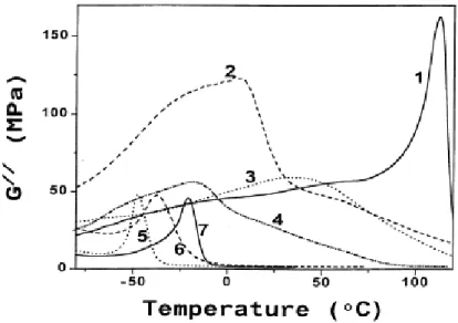
The shear storage (G′) and loss (G″) moduli of the neat components and the blends have been measured from −80 to 120°C. Although these properties have been measured for all the polymers and blends considered in this study, only the most representative data are reported in the next figures. Fig. 7 and Fig. 8 show temperature dependence of G″ and G′ for the blend components. The G″ vs. temperature curve shows the main relaxation characteristic of PS, PP, SBR, PEBU and EPR, which basically corresponds to the glass transition temperature (Tg) [11]. The broad relaxation of LDPE is associated with the relaxation of the branch points [17]. In the case of
HDPE, it is attributed to relaxation in the crystalline phase [17]. Among the core forming polymers, PP has the highest storage modulus and EPR has the lowest one ( Fig. 8). Moduli of the other POs have intermediate values, such that the modulus of the core-forming polymer covers a very large range.
Fig. 7. Temperature dependence of the loss modulus for the blend components: (1) PS; (2) PP; (3) HDPE-1; (4) LDPE; (5) EPR; (6) PEBU-3; and (7) SBR.
Fig. 8. Temperature dependence of the shear storage modulus for the blend components: (1) PS; (2) PP; (3) HDPE-1; (4) LDPE; (5) EPR; (6) PEBU-3; and (7) SBR.
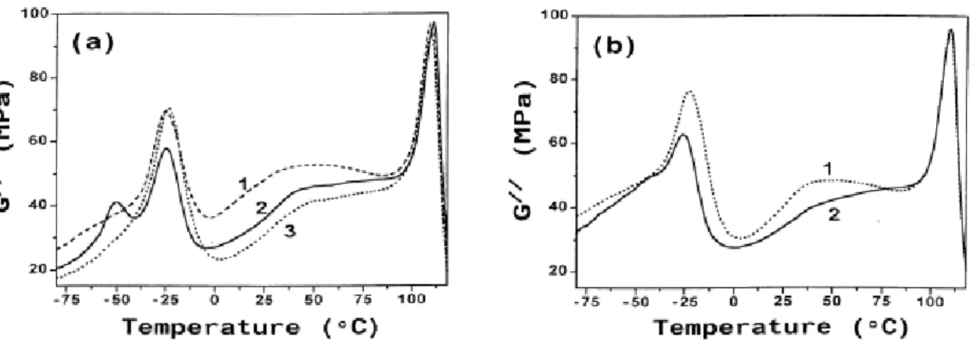
Fig. 9. Temperature dependence of the loss modulus for the PS/SBR/PO blends consisting of (a): (1) PP, (2)EPR, (3)LDPE; and (b) (1) HDPE-1, (2) PEBU-3.
Fig. 10. Temperature dependence of the shear storage modulus for the PS/SBR/PO blends consisting of (a): (1) PP, (2) EPR, (3) LDPE; and (b) (1) HDPE-1, (2) PEBU-3.
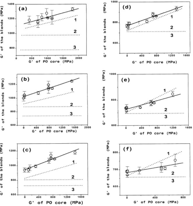
Fig. 11. Shear storage modulus of the PS/SBR/PO blends and theoretical predictions based on (3) and (4) at different temperatures and thus different G′ for the SBR shell: (a) T=−80°C, G′SBR=640 GMPa; (b) T=−40°C,
G′SBR=380 MPa; (c) T=−30°C, G′SBR=224 MPa; (d) T=−15°C, G′SBR=8 MPa; (e) T=0°C, G′SBR=1 MPa; (f)
T=25°C, G′SBR=0.5 MPa. The solid line and line 1 are the linear square fits for the experimental and theoretical
(interfacial situation (1) moduli, respectively. Lines 2 and 3 are representative of the interfacial situations (2) and (3)– (4), respectively.
Fig. 9 shows how the loss modulus changes with temperature for PS/SBR/PO blends. Two sharp peaks are systematically observed at ca. −23 and 110°C, which correspond to Tg of the shell-forming SBR and the PS
matrix, respectively. The glass transitions of EPR (−50°C) and PEBU (−37.5°C) are also observed. It should be noted that G″ is higher in the area of the SBR transition in the case of PP, HDPE and LDPE, more likely because the characteristic relaxation of these POs occurs in the same temperature range as SBR (Fig. 7). The very broad maximum which is observed between Tgs of SBR and PS, for blends containing HDPE and PP, might be
attributed to relaxation in the crystalline phase of these constituents. It must be noted that the relaxation typical of Tg of PS is independent of the other blend components. From the comparison of the G″ vs. temperature curves
for the blends and the constitutive components, it appears that the curves for each blend results as a first approximation from the superposition of the curves for the components involved, weighted by the composition.
Fig. 10 shows the dependence of the storage modulus, G′, on temperature for ternary blends containing PO of different types. As a rule, the modulus of the blends decreases sharply at Tg of SBR and PS. The storage modulus
of the blends depends on the modulus of the core-forming polymer, as shown by Fig. 11 at different
temperatures. These temperatures have been selected in such a way that the effect of the core stiffness on G′ of the blends could be estimated in relation to the modulus of the shell-forming SBR. The full line is the least squares fit of the experimental points. It is clear that the modulus of the SBR layer strongly controls the dependence of the blend modulus on the modulus of the PO core. As a rule, this experimental dependence has a positive slope.
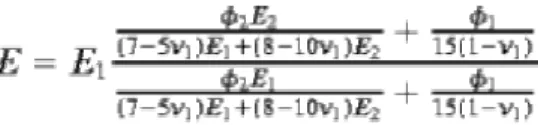
The Kerner equation valid to the shear modulus of two-component composites [18] has been recently extended to binary [19-20] and ternary [10 ; 21] polymer blends:
(3) where E, E1, E2 are the moduli for the binary blend, the matrix and the dispersed phase, respectively. 1, 2 are
the volume fractions of the matrix and the dispersed phase, respectively. ν1 is the Poisson ratio for the matrix.
The validity of this equation assumes that the stress transfer through the interface is ideal. In the absence of stress transfer, the Kerner equation is simplified, E2 being assumed to be zero:
(4) For the blends under consideration, four distinct interfacial situations may be identified: (1) ideal stress transfer from the PS matrix to the SBR shell and through the shell to the PO core; (2) ideal stress transfer from PS to SBR but not through SBR to PO; (3) poor stress transfer from the matrix to the SBR shell and ideal transfer from SBR to PO; (4) poor stress transfer from PS to SBR and from SBR to PO. Cases (3) and (4) are comparable since no stress transfer may occur from the PS matrix to both the SBR layer and the PO core. In this extreme situation, the modulus of the PS/SBR/PO ternary blends may be approximated to the modulus of the binary blend (of the same PS content as the ternary one) calculated by Eq. (4). Line 3 in Fig. 11 illustrates this extreme case. For the cases (1) and (2), the modulus can be calculated by the Kerner equation on the assumption that the stress distribution is uniform throughout the PS and the SBR phases and that the average stress is actually the macroscopic stress in the PS/SBR binary blend of the same relative content as in the ternary blend [10]. Therefore, the modulus of the binary PS/SBR blends has been calculated by Eq. (3). In the case (1), when stress is supposed to be transferred from the matrix to the PO core through the shell layer, Eq. (3) has been used to calculate the modulus of the PS/SBR/PO ternary blends while considering the PS/SBR blend as the matrix and PO as the dispersed phase. Line 1 in Fig. 11 is the least squares fit for the modulus calculated in this manner. For the case (2), Eq. (4) has been used to calculate the modulus of the ternary blends assuming that the PS/SBR blend is the matrix. Line 2 in Fig. 11 corresponds to this interfacial situation. It must be noted that the difference between lines 2 and 3 disappears above Tg of SBR (−23°C), whose the modulus is then very low. Since the
Kerner model has proved to be largely insensitive to variations in the Poisson ratio [21], this ratio for the PS/SBR "matrix" has been supposed to be the same as for PS. The Poisson ratio of LDPE has been used for the PO core whatever it is. The Poisson ratio for PS is 0.38 and 0.50 for SBR and PO [11 ; 22].
When SBR is in the glassy state (Fig. 11a–c), the comparison of the calculated and experimental moduli shows that the stress is transferred from the matrix to the core. At these temperatures, the slope of the experimental dependence is very close to that one predicted for the interfacial situation. That the experimental data are somewhat higher than the predicted ones is thought to originate from a rather strong adhesion at the PS/SBR and SBR/PO boundaries.
At temperatures higher than Tg of the shell, although the experimental data are closer to the theoretical ones, the
slope of the experimental dependence decreases with respect to the slope of line 1 representative of the ideal stress transfer through the shell to the core. Therefore, in spite of good adhesion at the PS/SBR and SBR/PO boundaries, there is a gradual shift from the interfacial situation (1) to situation (2) as the shell stiffness is decreased. The reason for this observation might be found in increasingly more important dissipation of energy and thus reduced stress transfer from the core through the rubbery envelope.
Fig. 12 shows the dependence of the impact and ultimate tensile strengths and the elongation at break measured at room temperature on the storage modulus of the core-forming polymer. The impact strength decreases as the core modulus is increased, the opposite tendency being observed for the ultimate strength. The elongation at break is essentially independent of the core-forming polymer. Although not in a spectacular manner, the mechanical properties of the ternary blends containing core–shell dispersed phases depends on the stiffness of the core under ambient conditions.
Fig. 12. Impact strength (a), ultimate tensile strength (b) and elongation at break (c) of the PS/SBR/PO blends versus the storage modulus of the PO cores.
5. Conclusions
The morphology and mechanical properties of ternary blends consisting of PS matrix and PO/SBR core–shell dispersed phases have been studied. Whatever the polyolefin (PO) used, it forms cores in SBR domains. Upon increasing the viscosity of PO, the size of the cores and the SBR domains including them increases. Compression molding of the blend samples does not change the blend morphology, except for the size of the PO and the SBR domains and the thickness of the rubbery layer around the PO cores, which increases as result of coalescence. The comparison of the experimental shear storage modulus of the blends with the theoretical predictions by the Kerner model indicates that the extent of the stress transfer from the matrix to the core through the shell depends on the modulus of the SBR layer modulus. The ultimate mechanical properties of the blends show some
dependence on the stiffness of the PO core. Acknowledgements
The authors are grateful to the "Services Fédéraux des Affaires Scientifiques, Techniques et Culturelles" (SSTC) for general support in the frame of the "PAI-4: Supramolecular Chemistry and Supramolecular Catalysis". They also thank Mrs Martine Dejeneffe for TEM observations. I.L. is indebted to (SSTC) for a fellowship.
References
[1] Hobbs SY, Dekkers MEJ, Wafkins VH. Polymer 1988;29:1598.
[2] Nemirovski N, Siegmann A, Narkis N. J Macromol Sci-Phys 1995; B 34:459. [3] Winerich D, Nemirovski N, Siegmann A, Narkis N. J Macromol Sci-Phys 1997; B36:247. [4] Lee MS, Lodge TP, Macosko CW. J Polym Sci, Polym Phys Ed 1997; 35:2837. [5] Guo HF, Packirisamy S, Gvozdic NV, Meier OJ. Polymer 1997; 38:785. [6] Guo HF, Gvozdic NV, Meier OJ. Polymer 1997; 38:4915.
[7] Favis BD, Chalifoux JP. Polym Engng Sci 1987; 27:1591. [8] Favis BD. Macromol Chem, Macromol Symp 1992; 56:143. [9] Wu S. Polym Engng Sci 1987;27:335.
[10] Luzinov I, Xi K, Pagnoulle C, Huynh-Ba G, Jérôme R. Polymer 1999;40:2511. [11] van Krevelen DW. Properties of polymers. Amsterdam: Elsevier, 1990 (chaps 6 and 8). [12] Oshinski AJ, Keskkula H, Paul DR. Polymer 1996;37:4891.
[13] Yoshida M, Ma JJ, Min K, White JL, Quirk RP. Polym Engng Sci 1990; 30:30. [14] Fortelny I, Zivny A. Polymer 1998; 39:2669.
[15] Favis BD. J Appl Polym Sci 1990; 39:285.
[16] van Gisbergen JGM, Meijer HEH. J Reol 1991; 35:63.
[17] Ward IM. Mechanical properties of solid polymers. Chichester: Wiley, 1979 (chap 8). [18] Kerner EH. Proc Phys Soc 1956;69B:808.
[19] Leclair A, Favis BD. Polymer 1996; 37:4723.
[20] Kunory T, Geil PH. J Macromol Sci Phys 1980; 18B:93. [21] Rôsch J. Polym Engng Sci 1995;35:1917.

![[PDF] Introduction complet pour démarrer avec ActionScript | Cours informatique](data:image/gif;base64,R0lGODlhAQABAIAAAP///wAAACH5BAEAAAAALAAAAAABAAEAAAICRAEAOw==)