Publisher’s version / Version de l'éditeur:
Vous avez des questions? Nous pouvons vous aider. Pour communiquer directement avec un auteur, consultez la première page de la revue dans laquelle son article a été publié afin de trouver ses coordonnées. Si vous n’arrivez pas à les repérer, communiquez avec nous à PublicationsArchive-ArchivesPublications@nrc-cnrc.gc.ca.
Questions? Contact the NRC Publications Archive team at
PublicationsArchive-ArchivesPublications@nrc-cnrc.gc.ca. If you wish to email the authors directly, please see the first page of the publication for their contact information.
https://publications-cnrc.canada.ca/fra/droits
L’accès à ce site Web et l’utilisation de son contenu sont assujettis aux conditions présentées dans le site LISEZ CES CONDITIONS ATTENTIVEMENT AVANT D’UTILISER CE SITE WEB.
8th International Conference on Short & Medium Span Bridges [Proceedings], pp.
237-1-237-10, 2010-08-03
READ THESE TERMS AND CONDITIONS CAREFULLY BEFORE USING THIS WEBSITE. https://nrc-publications.canada.ca/eng/copyright
NRC Publications Archive Record / Notice des Archives des publications du CNRC :
https://nrc-publications.canada.ca/eng/view/object/?id=fc81aeda-0c63-4c79-9b23-0cf610ebbd14
https://publications-cnrc.canada.ca/fra/voir/objet/?id=fc81aeda-0c63-4c79-9b23-0cf610ebbd14
NRC Publications Archive
Archives des publications du CNRC
This publication could be one of several versions: author’s original, accepted manuscript or the publisher’s version. / La version de cette publication peut être l’une des suivantes : la version prépublication de l’auteur, la version acceptée du manuscrit ou la version de l’éditeur.
Access and use of this website and the material on it are subject to the Terms and Conditions set forth at
Simplified flexural design approach of ultra high performance concrete
bridge girders
Proceedings of 8th International Conference on Short and Medium Span Bridges
Niagara Falls, Canada 2010
SIMPLIFIED FLEXURAL DESIGN APPROACH OF ULTRA HIGH
PERFORMANCE CONCRETE
BRIDGE GIRDERS
Husham Hammadi Almansour
National Research Council Canada – Institute for Research in Construction, Canada Zoubir Lounis
National Research Council Canada – Institute for Research in Construction, Canada
ABSTRACT
Ultra high performance fibre-reinforced concrete (UHPFRC) is a newly developed concrete material that provides very high strength and very low permeability. The renewal of aging highway bridges and the construction of new bridges using ultra high performance concrete can yield structurally efficient long life bridges, which will require minimum maintenance and low life cycle costs. A simplified flexural design approach of UHPFRC girders and a comparative study of the structural efficiency of UHPFRC and conventional precast prestressed concrete girder bridges are presented in this paper, and to compare its structural efficiency to conventional slab-on- concrete girder bridges. The proposed design approach is consistent with the Canadian Bridge Design Code (CHBDC) and is based on the state-of-the-art design recommendations for UHPFRC and checked using a three-dimensional finite element analysis. It is found that the use of UHPFRC in precast/prestressed concrete girders can yield a reduction of up to two girder lines with smaller girder sizes when compared to conventional concrete girders bridge. UHPC results in a significant reduction in concrete volume that can reach 40%, which turn leads to a more efficient design of the superstructure and a significant reduction in the dead loads on the substructure, which is very important for the safety of aging bridge substructures.
1. INTRODUCTION
Ultra high performance fibre reinforced concrete (UHPFRC) is a newly developed concrete material that provides very high strength and very low permeability. UHPFRC could enable major improvements over ordinary concrete (OC) and high performance concrete (HPC) bridges in terms of structural efficiency, durability and cost-effectiveness over the long term. The construction of new bridges and the renewal of aging highway bridges using UHPFRC can lead to the construction of structurally efficient long life bridges that will require minimum maintenance resulting in low life cycle costs. Slab on precast girders is one the most common forms of structural systems used for the construction of highway bridges in North America due to their good long-term performance and cost effectiveness (Lounis and Cohn 1993; Lounis and Mirza 1997). The use of standard precast/prestressed girder sections is a popular and cost-effective choice for the construction and replacement of short and medium span bridges, as well as the construction of long span bridges using segmental construction and splicing girders by post-tensioning (Lounis, and Mirza, 1997). Throughout the last four decades, there was a considerable growth in the use of high strength/high performance concrete (HSC/HPC) in highway bridges. The development of UHPFRC represents a major innovation in the concrete construction industry that can help overcome some of the shortcomings of ordinary concrete (OC) and HPC/HSC. UHPFRC provides strengths that are at least twice the compressive and tensile strengths of HPC/HSC and permeability to chlorides that is 2 to 3 orders of magnitude lower than that of HPC/HSC. The use of UHPFRC in slab on girder bridges could lead to considerable reduction in the number of girders and girder size, and could enable the construction of long life bridges.
The first UHPFRC road bridge, which is a two simply supported spans of 22 m each highway overpass bridge was constructed and opened to traffic in France, 2001(Hajar, et al. 2004). More recently, a 33.8 m span UHPFRC bridge was designed and constructed in Iowa and opened to traffic in late 2005, and a 47 m single span road bridge was
built in France in 2005 (Resplendino, et al. 2006). The only available design guidelines for UHPFRC structures are the French Interim Recommendations (AFGC 2002), which provide modifications to the existing French design standards for reinforced and prestressed concrete structures. The recent draft recommendation of the Japan Society of Civil Engineers for the design and construction of UHPFRC structures proposed some modifications compared to the earlier French recommendations (JSCE 2009). Both recommendations are not developed specifically for highway bridge structures and not necessarily compatible with the Canadian bridge design code safety requirements and traffic load models. Hence, there is a need to develop a procedure for the design of UHPFRC bridges according to the Canadian Highway Bridge Design Code (CAN/CSA-S6-06 or CHBDC 2006). An iterative analysis and design procedure was proposed for concrete slab on precast/prestressed UHPFRC girders (Almansour and Lounis, 2007) and a preliminary evaluation of the structural performance of this type of bridge and comparison to typical OC bridges is carried out (Almansour and Lounis, 2008).
The objective of this paper is to propose a simplified flexural design approach of UHPFRC girders, which is then used to undertake a comparative study of the structural efficiency of UHFRC girder bridges and conventional prestressed concrete girder bridges.
2. MECHANICAL PROPERTIES OF ULTRA HIGH PERFORMANCE CONCRETE
Ultra high performance concrete (UHPFRC) was developed based on advances in nano-technology to achieve a concrete with very low permeability and very high strength. UHPFRC is designed through ultra-high dense packing by means of refined mix-design involving minimum water cement ratio (w/cm < 0.2), high percentages of cement and silica-fume, fine sand and no coarse aggregates (Ulm and Acker, 2008). UHPFRC is reinforced at the micro level by means of uniformly distributed short fibres with a percentage that can vary from 2 to 12 % (by volume of concrete). The fibre length is ranging from 1 to 20 mm and either constant or variable. Depending on the fibres length and the volumetric proportion, there are three major types of UHPFRC: (i) UHPFRC with high proportions of short fibres, introduced in Denmark in 1987 (Rossi, 2008); (ii) UHPFRC with intermediate proportion of long fibres, introduced in France 1995; and (iii) UHPFRC with very high proportion of fibres of various lengths, introduced in France 2000 (Rossi, 2008).
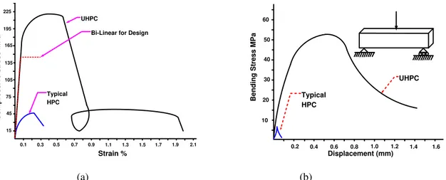
The fibre reinforcement of UHPFRC, heat treatment and its high homogeneity contribute to eliminate the initiation of extensive early age cracks that are the major disadvantage of high strength/ high performance concrete. The superior macro-level mechanical properties of UHPFRC, such as very high compressive and tensile strengths and high modulus of elasticity, high ductility, and high fatigue strength, could enable the development of lighter bridge superstructures that would reduce the number of girders and/or support longer spans than conventional HPC/HSC. The compressive strength of UHPFRC can vary in a very wide range from 120 to 400 MPa, its direct tensile strength can vary from 8 to 30 MPa, and its modulus of elasticity is in the range of 60 – 100 GPa (Acker et al. 2004). Typical stress-strain relationships and typical tensile (bending) stress versus displacement of UHPFRC are compared to those of a typical high performance concrete in Figure 1-a and Figure 1-b, respectively. Figure 1-a also shows the conservative elasto-plastic approximation of compressive behaviour of UHPFRC that is assumed in design.
The uniform distribution of the fibres in the UHPFRC matrix is hard to achieve and different fibre orientations are observed in practice. Since the fibre alignment could result in local or overall anisotropy in UHPFRC, the mechanical properties are affected locally or throughout the entire structural element depending on the affected region, location and size. Furthermore, the anisotropic behaviour adds more complications in the structural analysis of UHPFRC systems; nevertheless, in some situations the anisotropy could improve the overall performance of the structural element if it is properly accounted for in the structural design. To simplify the analysis and design procedure and given the lack of comprehensive experimental data on UHPFRC behaviour, it is generally recommended to use a reduction factor applied to the homogenized properties from the standard material tests (AFG-IR 2002; JSCE- 2006).
General design recommendations for the use of UHPFRC in reinforced and prestressed concrete structures were first developed in France (AFG-IR 2002), followed by the Japanese recommendations (JSCE No 9, 2006) and recently a new set of design recommendations for UHPFRC structures was released in Germany (2008). FIB is also developing a first set of design rules for UHPFRC (Walraven, 2008). However, no recommendations have been developed yet in North America. On the other hand, no specified recommendations for the use of UHPFRC in bridge design have been developed in Europe or North America.
0.1 0.3 0.5 0.7 0.9 1.1 1.3 1.5 1.7 1.9 2.1 15 45 75 105 135 165 195 225 C o m p re s s iv e s tr es s MPa Strain % UHPC Typical HPC
Bi-Linear for Design
0.2 0.4 0.6 0.8 1.0 1.2 1.4 1.6 10 20 30 40 50 60 B e n d in g S tr e s s M P a Displacement (mm) UHPC Typical HPC
Figure 1. Mechanical properties of UHPFRC and OC: (a) Stress-strain relationships; and (b) Flexural stress – displacement
3. PROPOSED DESIGN APPROACH FOR PRESTRESSED UHPFRC GIRDERS 3.1 General
Most existing structural concrete design codes and standards limit the concrete compressive strength to a maximum of 80 to 85 MPa. Given the lack of data on UHPFRC performance, the design approach will be developed based on existing international recommendations (AFGC 2002; JSCE 2006) ; requirements of the Canadian Highway Bridge Design Code (CHBDC 2006), and use of engineering judgment. The material reduction factor at ultimate limit state (ULS) for UHPFRC must be calibrated based on lifetime target reliability index of CHBDC (2006). A rigorous reliability-based analysis is needed to determine the appropriate reduction factor for UHPFRC to ensure lifetime reliability indices that are consistent with the requirements of the bridge design code for flexural and shear design. However, given the lack of data on strength variability and performance to failure of UHPFRC beams, the material reduction factors are assumed conservatively in this study to be the lowest of the values given by the UHPFRC design recommendations (AFGC2002) and CHBDC (2006).
3.2 Serviceability Limit States
Given the lack of data on the performance of UHPFRC girders in the field, the design of highway bridges will be based on the criteria of no crack at transfer and at serviceability limit states (SLS), by keeping the tensile stresses below the cracking limit for both cases (i.e. assuming fully prestressed girders). Compressive strength of heat-treated UHPFRC gains almost 95% of its full strength within the first few days and way before transfer (JSCE- 2006). A conservative limit on the compression strength at transfer of 85% of the 28 day compressive strength (f’c)
is assumed in the present paper, or (i.e. f’ci = 0.85 f’c). The allowable compressive stress at transfer is taken
conservatively as fci = 0.6 f’ci (CHBDC 2006). The allowable tensile strength at transfer fcri is assumed equal to: ' ci cri 0.4 f f ] 1 [
The allowable compressive stress
c
f at SLS is equal to 60% of the UHPFRC compressive strength (Figure 2), i.e.,
' c f 0.60 f [2] c
The maximum tensile strength is equal to the first crack strength (
f
cr)
. The maximum deflection for superstructurevibration should satisfy the CHBDC 2006 code limits.
Although the CHBDC (2006) and AFGC (2002) allow tensile stresses that exceed the cracking limit at SLS, the tensile stress is limited to the cracking limit in this paper. Using AFGC (2002) recommendations, the allowable tensile strength of UHPFRC is given by:
K w σ f [3a] 0.3 t
Where ft is the allowable tensile stress, σ(w0.3) is the tensile stress corresponding to a crack width of 0.3 mm (see
Figure 2) and represents the basis for fibre tensile strength, and 1/K is an orientation coefficient that accounts for the actual variability in fibre orientation due to placement. K is equal to 1.25 for all loading other than local effects (which is used in this paper), and equal to 1.75 for local load effects. The allowable tensile strength at serviceability limit state can be conservatively expressed as:
' c t 0.4 f
f
[3b]
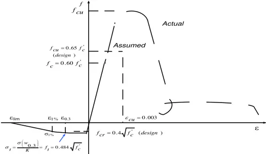
This value will be the design-cracking limit at SLS, which is much lower than the direct tension test result of UHPFRC (Figure 2). e ' 60 . 0 fc c f ' 484 . 0 3 . 0 c f t f K w t e0.3 e1% 1% fcr 0.4 fc' (design ) f elim ) ( ' 65 . 0 design c f cu f 003 . 0 cu e Actual Assumed cu f
Figure 2. Assumed tensile and compressive behavior of UHPFRC for design
3.3 Proposed Approach for Flexural Design of UHPFRC Girders at Ultimate Limit State
At the Ultimate Limit State (ULS), a bi-linear stress-strain relationship is assumed as shown in Figure 2 that includes: (i) a first line from zero stress and zero strain up to strength of (fcu) and a strain of (fcu/Euhpc); and (ii) a
second line that is horizontal up to the ultimate strain of εcu = 0.003. The ultimate strength (fcu) is given as (AFGC
2002) and adapting to CHBDC (2006) yields:
θ f 0.85 f
[4a] cu c cj
where: fcj is the cylinder compressive strength at age j, which is taken in the present study equal to 28 days; : is a
factor related to the probability of load application period or rate of loading. = 0 for loads with application periods equal or exceeding 24 hours, = 0 for loads applied over a period between 1 hour and 24 hours, and = 0.85 for loads with periods of application of less than one hour; c: is a coefficient that takes into account the variability of
0.75 for ULS load combinations involving permanent and transitory loads and c = 0.95for load combinations
involving exceptional loads (AFGC 2002). Substituting the factors values equation (4a) conservatively yields: '
c cu 0.65f
f
[4b]
At ULS, the factored bending moment and shear force should be less or equal to the factored flexural strength and shear strength, respectively. A ductile failure at ULS should be ensured so that the tensile stresses in the prestressing steel are kept below the factored ultimate tensile strength (i.e. 0.95 fpu) by ensuring that the relative neutral axial
depth (c/dp) is less than 0.5, where c is the distance from the extreme compression fibre to neutral axis and dp is the
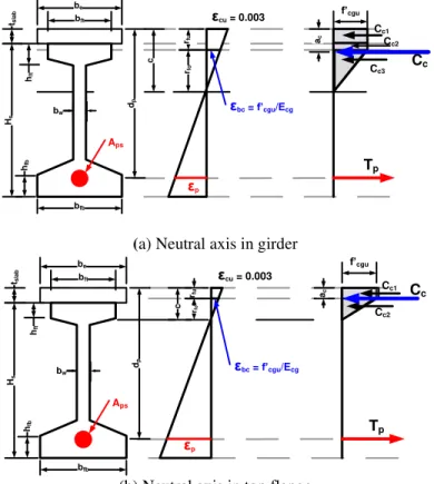
distance from the extreme compression fibre to the centroid of the tendons, as shown in Figure 3. In addition, the flexural resistance should be higher than 1.2 Mcr, where Mcr is the cracking moment.
Assuming that the slab acts compositely with the girders through a composite section formed from concrete slab of thickness tslab and UHPFRC prestressed girder of depth Hs, (see Figure 3-a & b). The equivalent slab width is equal
to the effective slab width (according to CHBDC 2006) divided by the modulus of elasticity ratio (Egirder/Eslab).
tsla b Hs dp bft be bfb bw hft hfb rfu rfo Aps Cc1 Cc2 Cc3 Tp εcu = 0.003 εbc = f’cgu/Ecg εp f’cgu c Cc ac
(a) Neutral axis in girder
tslab Hs dp bft be bfb bw hft hfb rfu rfo Aps Cc1 Cc2 Tp εcu = 0.003 c εbc = f’cgu/Ecg εp f’cgu Cc ac
(b) Neutral axis in top flange
Figure 3. Strain and stress distribution at ULS of flexural action in UHPFRC girders
Assuming a linear strain distribution over the composite section depth and a bilinear stress distribution for UHPFRC under compression and the tensile resistance of UHPFRC under tension is ignored. From Figure 3, equilibrium conditions dictates that Cc = Tp, where Cc = Σ Cci is the sum of all the internal compressive force components on the
cross section, and Tp is the tensile force in the prestressing steel at ULS.
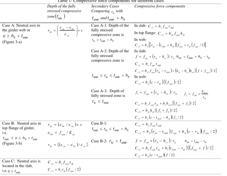
m 1 i ci c C C [5]Where, m is the number of compressive force components according to the suitable case given above as summarized in Table 1. The location of the resultant Ccfrom the top compression fiber of the composite section is given by:
m 1 i ci ci m 1 i ci C C a C a [6]where, aciis the location of force component Cci from the top compression fiber of the composite section.
The centroid of the prestressing steel tendons is then calculated for the critical flexural sections, and through a trial-and-error process, the equilibrium of the internal forces is satisfied (Cc = T). Hence, the flexural resistance of
UHPFRC is given by:
p c
c r C d aM
[7]
where, dpis the depth of the prestressing steel from the top compression fiber.
3.4 Shear Design of UHPFRC Girders at Ultimate Limit State
After UHPFRC cracks, the randomly distributed fibers provide most of the shear capacity. However, there is a lack of knowledge and data on how to include the effect of the fiber reinforcement into such an expression of shear strength.
Table 1: Compressive force components for different cases
A simplified approach is used to estimate the shear strength of UHPFRC (with at least 2% volumetric fiber content), which is based on the proposed models of AFGC (2002) and JSCE (2006). The shear resistance (Vr) of UHPFRC or
Depth of the fully stressed compressive zone
fcgu Secondary Cases Comparing rfuwith slab t andtslab hftCompressive force components
Case A: Neutral axis in the girder web or
slab ft t h c (Figure 3-a) c r cu bc cu fu e e
e Case A-1: Depth of the fully stressed compressive zone is ft slab fu t h r In slab: slab cgu e c b f t C 1 In top flange: ft cgu ft c b f h C 2 In web:
/2
3 w fu slab ft cgu fo cgu
c b r t h f r f
C
Case A-2: Depth of the fully stressed compressive zone is ft slab fu slab r t h t In slab:
fo cw
fo cgu r h r f f / hcw tslab hft rfu slab cgu e c b f t C 1
/2
2 ft cgu fu slab ft w cw cgu
c b f r t b b h f f C In web:
/2
3 w fu cgu c b c r f C Case A-3: Depth of fully stressed zone is
slab fu t r
fo cw
fo cgu r h r f f1 / fo cw cgu r h f f 2 2
1 /2
1 1 b f r bh f f Cc e cgu fu e cw cgu
1 2 /2
2 b h f f Cc ft ft
2/2 3 b c t h f Cc w slab ftCase B: Neutral axis in top flange of girder, i.e. slab ft slab c h t t (Figure 3-b)
c rfo ebc /ecu cg cgu bu f /E e
rfu ecu ebc /ecu Case B-1: ft slab fu slab r t h t slab cgu e c b f t C1
/2
2 ft fu slab cgu ft fu cgu
c b r t f b c r f
C
Case B-2: rfu tslab f fcgu
rfohcw
/rfo fu slab cw t r h
/2
1 b f r b t r f fCc e cgu fu e slab fu cgu
/2 2 b c t f
Cc ft slab
Case C: Neutral axis is located in the slab, i.e.ctslab fu cgu e c b f r C 1
/2
2 e fo cgu c b r f C the shear load carrying mechanism is hypothetically divided it into three components: (i) first component represents the composite action of the matrix and the fiber (Vc); (ii) the second component represents the shear capacity
provided by the average fiber tensile resistance (before fiber pull out) acting along the diagonal cracks (Vf); and (iii)
the third component is shear capacity provided by the stirrups (Vs) and prestressing (Vp). The overall shear
resistance is given by:
c f p s
r V V V V
V
[8]
The limited available experimental results (FHWA-HRT-06-115, 2006) are in agreement with AFGC (2002) estimation; however, more research is needed to assess the shear resistance of UHPFRC.
z b f φ 0.24 V [9] cj 0 E c c
The coefficient E characterizes the current uncertainty regarding the possibility of extrapolating to UHPFRC the
design equations established for HPC for which f’c 85 MPa and is taken equal to 1.15 for ULS 1 and 2; fcj is the
concrete compressive strength at age j days (or 28 days in the present paper), b0 and z are the effective web shear
width and depth, respectively. Then the concrete contribution to shear strength is Vc 0.16 fc' b0z, and the fiber contribution Vf is given by:
u bf p f tan Sσ V [10]
where σpis the residual tensile strength:, which is given by:
lim w 0 lim p σ(w)dw w 1 K 1 σ [11]where, Wlim = max(Wu, 0.3 mm); Wu =lcεu, εu is the ultimate strain of 0.003, lc = ⅔h, h is the total height of the
section;( w)is the experimental characteristic post-cracking stress corresponding to a crack width w; wuis the ultimate crack width; S is the area of the fiber effect, S = 0.9b0dp or S = b0z; K is the fiber orientation coefficient for
general effect (K = 1.25); bf =1.3 and u is the angle of the compression struts and lower-bounded to 30º (AFG-IR
Cl 7.3,3, 2002).
The shear reinforcement contribution, Vs, is calculated in the same way as for OC girders following CHBDC (2006).
It is important to mention here that the French Recommendations (AFGC 2002) allow the use of shear reinforcement with UHPFRC structural elements in a similar manner as for conventional concrete elements where (f’c ≤ 80 MPa).
On the other hand, the Japanese recommendations (JSCE 2006) provide more restrictions on the use of
non-prestressed reinforcements with UHPFRC as the use of reinforcement with UHPFRC would result in disturbance of fiber orientation that would cause cracks. Some cracks may also develop due to internal constraints of UHPFRC due to shrinkage unless the effects of the constraint are properly evaluated and measures to prevent cracks are properly taken into account (JSCE 2006).
4. ILLUSTRATIVE EXAMPLE 4.1 Proposed Iterative Design Procedure
The iterative design procedure proposed for prestressed UHPFRC bridge is illustrated in Figure 4. The procedure involves two steps: (i) a simplified semi-analytical approach to obtain the preliminary feasible superstructure design; and then (ii) a refined finite element based analysis is carried out to check that the preliminary design is acceptable and if necessary modifications are required. The refined analysis generates a detailed stress distribution in all girders that enable to identify the zones of maximum stresses and to optimize the girder section and prestressing steel area and layout.
In order to verify the structural efficiency of UHPFRC bridge girders, a comparative study of two types of girder bridges: (i) the first system consists of conventional concrete slab compositely integrated with OC girders, and (ii) the second system consist of a slab of the same geometrical and material properties compositely integrated with UHPFRC girders. Both bridge systems are designed support the same traffic load and superimposed dead loads. The major parameters in this comparison are the number of girders (or the girder spacing); the girder size, stresses at SLS, the girders deformations under service loads and the ultimate bridge load capacity. Other parameters such as slab thickness, span length, number of lanes, traffic speed, prestressing system pattern, and boundary conditions are
assumed the same for both bridges. The traffic load and bridge design is complying with all Serviceability and Ultimate Limit States (SLS and ULS) requirements of CHBDC (2006).
The bridge center-to-center span is 25 m and the total width of the deck including the barrier walls is 11.6 m. The slab thickness for both bridges is 175 mm. Two types of live loads are applied on the deck surface: (i) a lane loading; and (ii) a single moving truck. For multi-lane loading, modification factors of 0.9 and 0.8 are applied for the two lanes and three lanes, respectively. Low-relaxation seven-wire strands, Grade 1860, with nominal diameter of 12.7 mm, nominal area of 98.7 mm2, and tensile strength (fpu) of 1860 MPa are used. CHBDC (2006) limits the
minimum effective stress in tendons to 0.45 fpu, the maximum stress at jacking to 0.78 fpu; the maximum tensile
stress at transfer to 0.74 fpu; and the maximum stress at ultimate to 0.95 fpu. The total prestress losses are estimated
to be 17% of the ultimate strength.
The materials properties of OC bridge are selected to match the properties of similar existing bridges. The compressive strength of the slab concrete is taken as f’cs = 30 MPa. For OC girders, f’cg = 40 MPaand at transfer
f’cgi = 30 MPa. Five CPCI 1400 (Figure 5) are required for the OC bridge with a girder spacing of 2.32 m. It is found
that the use of twenty straight tendons at the bottom span and ten tendons linearly deflected on one third of the girder span are sufficient. The centroid of the straight tendons is 100 mm from the bottom fiber while the centroid of the deflected tendon in the girder ends is 850 mm and in the middle third is 110 mm. The allowable compressive stress at transfer is 0.6 f’cgi(or 18 MPa), and the allowable tensile stress at transfer is 0.2 '
cgi
f (or 1.1 MPa). At SLS, the allowable compressive stress is 0.6 f’cg(or 24 MPa) and the first crack strength is 0.4 '
cg
cr f
f (or 2.53 MPa). The OC bridge design is governed by the tensile strength or cracking limit at SLS. The maximum deflection for superstructure vibration should satisfy the CHBDC 2006 code limits. For ULS, the reduced flexural capacity of the girder is (7300 kNm), which is higher than the factored moment (5440 kN.m and much higher than the cracking moment (3100 kN.m). The girder design is checked for ductile failure as the moment resistance is developed with c/dp = 0.074 far less than 0.5 The shear reinforcement at the critical shear section is provided by 10M stirrups at 125
mm spacing.
For the UHPFRC bridge, the compressive strength of the deck slab is assumed f’cs = 30 MPa. The compressive
strength of the ultra high performance concrete of the girders is f’cg = 175 MPaand at transfer f’cgi = 0.85 f’cg (or 149
MPa). Three CPCI 900 girders (Figure 5) are found sufficient, with a spacing of 4.0 m. The allowable compressive stress at transfer is 0.6 f’cgi or (87 MPa) and the allowable tensile stress at transfer is 4.88 MPa. At SLS, the
allowable compressive stress is 105 MPa and the cracking strength is 5.3 MPa. Similar to the OC girder, the design of UHPFRC girders is also governed by the cracking limit at SLS. The maximum for superstructure vibration satisfies the CHBDC 2006 code requirements. For ULS, the reduced flexural capacity of the UHPFRC girder is found (10,110 kNm) higher than the factored moment (8,260 kNm) and is much higher than the cracking moment (3,470 kNm). The girder design is checked for ductile failure as the moment resistance is developed with c/d = 0.085 being far less than 0.5. The shear reinforcement at the critical shear section is provided by 10M stirrups at 100 mm spacing.
4.2 3-D Finite Element Modeling of UHPFRC Girders Bridge
A linear elastic three-dimensional (3-D) finite element model (FEM) is developed to determine the stress distribution in all girders that make up the two investigated bridges. This 3-D FEM model enabled more accurate predictions of the stresses in all girders than the simplified analysis approach of the CHBDC (2006). Both the deck slab and girders are modeled using shell elements, while the prestressing tendons are modeled using cable elements. The prestressing losses, deformations and relaxation are accounted in the model.
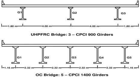
The FEM results indicate that the maximum stresses are found in the central girders for both OC and UHPFRC for the case of two lanes loading. On the other hand, the maximum stresses are found in the external girders for the case of three-lanes loading. In general, the results show that the maximum stresses for the three-lane loading case are less critical than those of the two-lane loading case. It also shows that the most critical girders are the central girder (G3) for the OC bridge and the internal girders (G2) for the UHPFRC bridge as shown in Figure 5. The results of the finite element model also show that the compressive stresses at ULS in the top fibers at midspan and bottom fiber of support span of the critical girders identified above are well below the ultimate stress levels for both OC and UHPFRC girders.
4.3 Comparison of Structural Efficiency of UHPFRC and OC Bridges
The use of UHPFRC enables a reduction in the number of girders from five to three and the size of the girder is also reduced from CPCI 1400 to the minimum provided size CPCI 900. The weights of the girders per unit deck area are 427 kg/m2 for the OC bridge and 158 kg/m2 for the UHPFRC bridge. The total weight per unit area of the superstructure, including the deck slab are 847 kg/m2 for the OC bridge and 578 kg/m2 for the UHPFRC bridge.
Figure 4. Design procedure for UHPFRC and OC bridges
G1 G2 G3 G4 G5
1.16 m 2.32 m 2.32 m 2.32 m 2.32 m 1.16 m
OC Bridge: 5 – CPCI 1400 Girders UHPFRC Bridge: 3 – CPCI 900 Girders
G1 G3
1.80 m 4.00 m 4.00 m 1.80 m
G2
Figure 5. Comparison of UHPFRC and ordinary concrete precast PC girder bridges
Consequently, UHPFRC results in 32% reduction in the total weight of the superstructure and 63% reduction in the weight of the girders. This reduced weight of UHPFRC superstructure will lead to a reduced size of the substructure. If the cement content in OC girders bridge is assumed equal to 380 kg/m3 and in UHPFRC is 1114 kg/m3 (Hajar et
Initial UHPC / OC Bridge Superstructure Section
Simplified Analysis and Design (CAN/CSA-S6-06 & AFGC-02)
Initial Design Adequacy
Check
Refined Analysis using Finite Element Model
Design Check Change Prestressing
Steel Area and/or Girder size and/or No. of Girders Yes No Yes No Final Bridge Design Change Prestressing
Steel Area and/or Girder Size
al. 2004), then a 7% reduction in the total cement used to cast five CPCI 1400 OC girders is realized when compared to the only three CPCI 900 UHPFRC girders. It is clear that a reduction in the weight of the superstructure will lead to a reduced size of the substructure (piers and abutments) and foundations and reduced overall cost of the bridge. Furthermore, a reduction in the concrete consumption will have considerable environmental benefits through the reduction of energy consumption and greenhouse gas emission (GHG) associated with the production of cement, extraction and transportation of raw materials to the construction site (Lounis & Daigle 2007).
5. CONCLUSIONS
A simplified design approach of concrete slab on UHPFRC girders bridge is proposed. The use of the Canadian Highway Bridge Design Code, CHBDC (2006) and the current international recommendations for design UHPFRC elements was investigated and a simplified flexural design approach is developed for prestressed concrete girders. The proposed procedure suggests a simple and conservative sectional analysis procedure similar to CHBDC procedure using a bilinear stress-strain model for UHPFRC under compression and ignoring its contribution to the tensile strength. For the investigated cases of 2 and 3 lane bridges with a 25 m span length, it is found that UHPFRC in precast/prestressed concrete girders yields a considerable reduction in the number of girders and girder size when compared to conventional OC girders bridge. UHPFRC yields a significant reduction in concrete volume and a slight reduction in the cement consumption. This weight reduction leads to a more efficient design of the superstructure that reduces the weight on the substructure.
6. REFERENCES
Acker, P., and Behloul, M.2004. Ductal® Technology: A large spectrum of properties, a wide range of application,
The Second International Symposium on UHPC, Kassel, Germany: 11-23.
AFGC - Association Française de Génie Civil 2002. Groupe de Travail Bfup. Ultra High Performance
Fiber-Reinforced Concretes: Interim Recommendations: Scientific and Technical Committee.
Almansour, H, and Lounis, Z. 2010. Innovative design approach of precast-prestressed girder bridges using ultra high performance concrete, Canadian Journal of Civil Engineering, V.37, 511-521.
Almansour, H, and Lounis, Z. 2008. Structural performance of precast prestressed bridge girder built with ultra high performance concrete, The Second International Symposium on UHPC, Kassel, Germany: 823-830.
American Association of State Highway and Transportation Officials. 2007. AASHTO LRFD Bridge Design
Specification, USA.
Canadian Prestressed Concrete Institute. 1996. Design manual, precast and prestressed concrete, Third Edition Canadian Standards Association. CAN/CSA-S6. 2006. Canadian Highway Bridge Design Code (CHBDC),
Canadian Standards Association, Mississauga, ON, Canada.
Hajar, Z., Lecointre, D., Simon, A., and Petitjean, J. 2004. Design and construction of the world first ultra-high performance concrete road bridges, The Int. Symp. on UHPC, Kassel, Germany, 39-48.
JSCE - Japan Society of Civil Engineers. 2006. Recommendation for design and construction of ultra high strength
fiber reinforced concrete structures (Draft), JSCE Guidelines for Concrete, No. 9, Japan.
Lounis, Z., and Cohn, M.Z. 1993. Optimization of precast prestressed bridge girder systems, PCI Journal, V. 38, No. 4, 1993, pp 60-77.
Lounis, Z., and Mirza, M.S. 1997. High strength concrete in spliced prestressed concrete bridge girders, PCI/FHWA
Int. Symp. on High Performance Concrete, New Orleans, LA, PCI, , 39-59.
Resplendino, J., Bouteille, S., Delauzun, O., Maleco, E., Dumont, C., Cantrelle, P., Chanliaud, G., Clergue, C., Lingard, Y., Capra, A., Linger, J., Martin, L., Guilloud, M. 2006. Construction of an overpass on the A51 Motorway, made of a prestressed box beam built with UHPFRC, in the French technologie of concrete, AFGC, The second fib congress, Naples.
Rossi, P. 2008. Ultra high-performance concretes, a summary of current knowledge, Concrete International, V.30, 31-34.
Ulm, F.J., and Acker, P. 2008. Nanoengineering UHPC materials and structures, Second International Symposium on UHPC, Kassel, Germany, pp 3-9.
U.S. Department Of Transportation, Federal Highway Administration. 2006. Structural behavior of UHPC
prestressed I-girders, Publication No. FHWA-HRT-06-115.
Walraven, J. 2008. On the way to design recommendations for UHPFRC, The Second International Symposium on