Automatic Design of the Gravity-Reducing Propulsion System of the
TALARIS Hopper Testbed
by
Jorge Canizales Diaz Lic. Physics
Universidad Aut6noma de Madrid, 2008
ARCHNES
MASSACHUSETTS INSTITUTE OF TECOLOG7Y
U BR'A R IE S
SUBMITTED TO THE DEPARTMENT OF AERONAUTICS AND ASTRONAUTICS
IN PARTIAL FULFILLMENT OF THE REQUIREMENTS FOR THE DEGREE OF
MASTER OF SCIENCE IN AERONAUTICS AND ASTRONAUTICS
AT THE
MASSACHUSETTS INSTITUTE OF TECHNOLOGY
JUNE 2012
@2012 Jorge Cahizales. All rights reserved.
The author hereby grants to MIT permission to reproduce and to
distribute publicly paper and electronic copies of this thesis document in whole or in part in any medium now known or hereafter created.
Signature of author:
______________men of Aeronautics and Astronautics
tK May 14 ,h 2012
Certified by:
SN '%Jeffrey A. Hoffman
Professor of the Practice of Aerospace Engineering , Thesis Supervisor Accepted by:
/
Eytan H. ModianoProfesso of Aeronautics and Astronautics Chair, Graduate Program Committee
Automatic Design of the Gravity-Reducing Propulsion System of the
TALARIS Hopper Testbed
by
Jorge Canfizales Diaz
Submitted to the Department of Aeronautics and Astronautics on May 15th, 2012 in Partial Fulfillment of the
Requirements for the Degree of Master of Science in Aeronautics and Astronautics
ABSTRACT
This thesis describes a Systems Engineering tool for automatic design, presents the results of its application to the problem of designing Earth-based reduced-gravity simulators, and compares the performance of the found optimal design solutions with that of the MIT TALARIS Hopper Testbed. Earth-based reduced-gravity simulators are platforms that allow hosted vehicles to experience a dynamic environment -from a guidance, navigation, and control perspective- analog to other planetary surfaces. Simulators are used for system development and operator training purposes. Specifically, reduced-gravity simulators produce a constant vertical thrust equal to a fraction of the weight of the studied vehicle, this yielding a perceived gravity equal to the gravity of the celestial body of interest. Planetary hoppers explore planetary surfaces through hopping, i.e. low altitude and short-duration flying. Recently, these systems have gained popularity as cost-effective means for planetary exploration due to their larger operational flexibility compared to other exploration systems.
The tool developed as part of this thesis eases the compilation and use of parts catalogs in the design task, includes real-time visualization of the search process, supports the output of multiple solutions that optimize conflicting goals, efficiently calculates Pareto frontiers of solutions, and can integrate external solvers and simulators seamlessly.
Chapter 1 overviews the engineering challenges associated with Earth-based reduced-gravity simulators applied to planetary hoppers. Chapter 2 provides the context knowledge required for the development of the individual tasks in this thesis. Chapter 3 discusses the engineering literature covering relevant previous work. Chapter 4 describes the selected approach and the tool that has been developed for the design of the propulsion system of the simulator. Chapter 5 discusses the applicability of the approach and design tool to the case of the MIT TALARIS Hopper Testbed. Chapter 6 summarizes the results and outlines avenues for future research in this field.
Thesis Supervisor: Jeffrey A. Hoffman
Acknowledgements
I owe my Master of Science at MIT to all these people, and more I might be forgetting. Luis Rouco, for his generous advices in electrical machines, and research in general. The owners of "al Fresco," for their delicious breakfasts.
Chris Han and Zach Bailey, for exposing me to MIT undergrads' unique work culture. "The windsorers," for their friendship and merriness.
Phillip Cunio, my best friend Mait6 Balda, and the sweet Ana Diaz, for being there empathically when I most needed it.
Prof. Dave Miller, Mr. Paul Bauer, and Dr. Alvar Saenz-Otero, for exciting me and teaching me with their way of managing development projects.
The Foundations of Caja Madrid and "la Caixa," for their exceptional fellowships. Maria Jos6 Nieves, Bruno Alvisio and Daniel Tofan, for hosting me. Google, Inc., for providing the return with which to pay this huge investment.
Professors Richard Battin, Dava Newman, Jonathan How, Olivier de Weck, Jeffrey Hoffman, Edward Crawley, Richard Binzel and David Miller, and doctoral candidate Alessandro Golkar, for teaching me from scratch the profession of a space engineer and researcher.
Dr. Lisa Varchol, for teaching me how to work hard without stop (which is a learned skill like any other), and being there when I most needed it.
Assistant Director Mary Murray, Assitant Director Eleanor Wolcott, Advisor Sylvia Hiestand, and Assistant Dean Jason McKnight, for their wise advice and generous help.
My best friends Carlos Pardo, Alessandro Golkar, and Dani Selva; and my girlfriend Cristina Freire; for their final push. The hardest part of a marathon is the home straight, and they carried me to the finish line.
My academic advisor, Professor Jeff Hoffman, for always investing his trust on me, and by doing so making me feel an empowering sensation of relief and the willingness to strive.
My family, for their unconditional love and support, and the sacrifices they have made for me. Sin ustedes no seria nada.
Table of Contents
Chapter 1. Sum m ary ... 13
1.1. Introduct .ion ... 13
1.2.Problem ... 13
1.3.M ain results...14
Automatic design and tradespace exploration software tool... 14
Scaling re latio ns ... 14
1.4.Structure of the thesis ... 15
Chapter 2. Context...17
2.1.Chapter outline ... 17
2.2.Gravity-reducing propulsion system of Talaris ... 17
A rch itectu re ... 18
U se o f C O T S ... 19
C u rre nt d esig n ... 19
2.3.Configuration design problem s ... 20
2.4. Review of som e design-solving procedures ... 21
Process 1: Solve the inverse problem ... 21
Process 2: Pick a base design and evolve it ... 22
Process 3: Automatically generate and evaluate many designs ... 24
2.5. Design problem sim plification through abstraction...27
Sources of abstraction knowledge. Tradespace exploration... 28
2.6.Overview of estim ating m ethods ... 28
A n a lo gy ... 29
Param etric m o de ls ... 29
D eta ile d a nalysis ... 29
2.7.Autom atic design tools...29
2.8. Rules engines ... 30
Parts and functioning of a rules engine... 30
CLIPS programming language... 31
Chapter 3. Relevant Literature...33
3.1.Ducted fans...33
Performance estimation ... 33
Parameters estimation ... 36
Performance equations... 37
Electronic Speed Controllers ... 41
DC Model: Motor constant and torque/speed curve ... 42
W ye (star) an d delta connections ... 43
Rated torque and electrical losses. Intermittent and continuous operation. ... 45
Other higher-order effects ... 47
Parameters estimation... 50
3.3.LiPo batteries ... 50
First-order estimation model ... 51
Selection. Ragone plots... 51
Higher-order effects5... 54
Parameters estimation... 60
3.4. Review of autom atic design tools...60
M O ST ... 6 1 Chapter 4. Problem and resolution ... 63
4.1. Difficulties of designing the Talaris gravity-reducing system ... 63
Designing by solving the reverse problem ... 63
Designing by evolving the current configuration ... 64
4.2.Adopted solution ... 68
Compile parts databases to feed the automatic generator. ... 69
Use an automatic generator ... 69
Summary of the solution... 70
4.3. Design strategy ... 71
Chapter 5. Results...73
5.1. Design solutions...73
V a lid ity ... 7 3 Design vector (AG) ... 73
M o d e ls used ... 74
So lutio n s... 74
5.2.Tradespace exploration products ... 78
Chapter 6. Conclusions and Future Research... 81
6.1.Thesis Sum m ary and Conclusions... 81
Automatic design tool ... 82
Considerations for the architecture of the Talaris EDF System ... 83
6.2.O pportunities for Future Research... 83
Chapter 7. Bibliography...87
Chapter 8. - Appendix A. Softw are docum entation... 95
8.2.Softw are Design and Im plem entation... 95
Software architecture ... 95
Software structure ... 97
8.3.Parts databases...97
Database Architecture ... 98
Chapter 9. - Appendix B. Overview of the CLIPS programming language ... 99
9.1.Procedural pa rt: Actions ... 99
Actions that modify the facts base... 100
9.2. Declarative part: Conditions ... 101
Capturing a matched fact in a variable ... 102
Matching lists of values... 103
List of figures and tables
Figures
Figure 2.1- Physical layout of the main components of the power-propulsion Talaris subsystems. ... 20 Figure 2.2 - Flowchart for second design method: pick a base design and evolve it...23 Figure 2.3 - Flowchart of the third design method: Generate and analyze many designs, ad select
am o ng the m . ... 25
Figure 3.1 - Setup of a permanent-magnet rotor, and a turn of a phase of the stator windings,
rotating around it. (Explanation in the text). ... 38 Figure 3.2 - Ideal speed-torque curve of a DC motor with internal resistance R and motor constant Kv
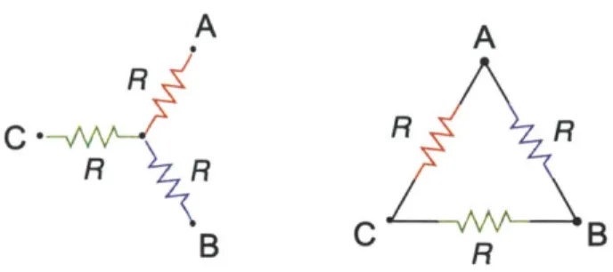
assum ing a constant voltage V ... 43 Figure 3.3 - Wye and delta connections of a BLDC motor. Left: The three phases of a motor, and their
terminals. Middle: Connection of the lines of the ESC for a wye configuration. Right:
Connection of the lines of the ESC for a delta configuration... 44 Figure 3.4 - Torque / Speed curve of a brushless DC motor. (Wikipedia, 2010)... 46 Figure 3.5 - Connections of the motor phase resistances for wye configuration (left) and delta
configuration (right). (Adapted from (W ikipedia, 2007))... 47 Figure 3.6 - Example efficiency of a BLDC motor as predicted by the losses model of Equations (3.30)
and (3.27) (dashed black), and the model of Equations (3.30) and (3.40) (solid blue). The horizontal axis represents the electrical working point V// of the motor. The right plot is a zoom ing of the left one. ... 49 Figure 3.7 - Adaptation of the series/parallel connections of battery packs to a changing motor
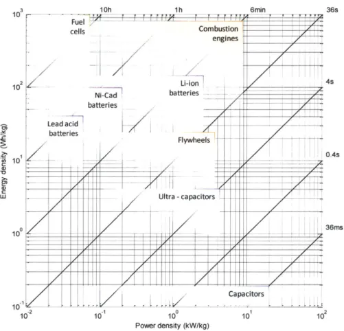
constant, for the same required fan speed (power) and flight time (energy)...52 Figure 3.8 - Ragone chart showing the capabilities of storage and delivery rate of various
energy-storage technologies. (Created with data compiled from several sources). ... 53 Figure 3.9 - Typical discharge curve of a LiPo cell: voltage vs. depth of discharge. The total charge is
rated at the point where the cell voltage crosses the 3V cutoff... 54 Figure 3.10 - Discharge curves of a hypothetical LiPo cell, at different discharge currents. From dark
blue to yellow, the higher the current, the lower the voltage. Note that the higher the current, the more conservative is the cutoff set at 3V. ... 56 Figure 3.11 - Ragone curve of a battery modeled as an ideal voltage source with internal resistance.
The specific energy is shown relative to the maximum specific energy the battery can store. The specific power is plotted relative to the maximum it can deliver (which is
beyond the rated specific power for LiPo batteries)... 58 Figure 4.1 - Attributes of a very high-level abstract model of an Electric Ducted Fan System, and the
equations relating them. On blue are marked the equations imposed by the ducted fans; on green, the equations imposed by the motors; on orange, the equations imposed by the batteries; and, on black, the equations imposed by the physical layout of the vehicle.. 63 Figure 4.2 - First-order estimation model equations for the Talaris EDF System...65 Figure 5.1 - Effect of changing the number of battery packs in series and parallel for the current
Talaris configuration. In the top branch are 2S configurations, and in the bottom branch, 1S configurations. In each branch, the individual configurations are iP - 9P from left to right. The X axis shows the discharge time of the batteries at full throttle; the Y axis, the
thrust produced beyond the weight of the EDF system; and the color encodes the weight
of the ED F system ... 75
Figure 5.2 - Zoom of the top branch of Figure 5.1, showing the configurations 2S4P (leftmost) to 2S9P (rig htm o st)...7 5 Figure 5.3 - The trade space of 159 feasible designs for Talaris. Weight and net thrust are plotted on the 2D axis, and the color of the squares represents total power. Since the ESCs were abstracted of this model, total power is a good first order indicator for the type of ESC needed, as higher power designs will require more massive and expensive ESCs...76
Figure 5.4 - Pareto frontier for the trade space of 470 feasible designs for Talaris. Dominated designs are shown as small circles whereas the 31 non-dominated designs appear as large diamonds. Utopia point is in the top left corner (i.e., maximum net thrust, minimum weight). The black diamond represents the current Talaris configuration...77
Figure 5.5 - Ragone plot of COTS LiPo batteries available as of August 2011. Dominated models are shown as small circles, whereas non-dominated ones are shown as large squares. ... 79
Figure 8.1 - Depiction of the different rule sets that act on each proposed design to implement the chronological backtracking algorithm. Inner loops represent higher priority on firing...96
Tables
Table 2.1 - Current configuration of the gravity-reducing system of Talaris... 19Table 4.1 - Current configuration of the gravity-reducing system of Talaris - repeat...64
Table 4.2 - Measured performance of the current Talaris configuration... 65
Table 4.3 - Rated values for the parameters of the current configuration of Talaris...66
Table 4.4 - Results of a first-order performance analysis of the current configuration of Talaris... 66
Table 4.5 - Results of a second-order performance analysis of the current configuration of Talaris. ... 68
Table 5.1 - Results of a first-order performance analysis of the current configuration of Talaris, accounting for battery Ohm ic losses... 73
Table 5.2 - Parameters of the design vector used for tradespace exploration. ... 74
Table 5.3 - Details of the design parameters and figures of merit for the 31 non-dominated designs. The details of the battery design are not populated at this level of abstraction...78
Table 5.4 - Non-dominated LiPo battery models with their specific energy, power, and cost. ... 80
Table 6.1 - List of manufacturers of high-power BLDC motors and drives. (source: (E. Lee, n d)) ... 84
Table 9.1 - Comparison of the syntaxes of C and CLIPS: Expressions with infix vs. prefix operators. The order of execution (syntax tree) is explicit in CLIPS, unlike in C... 99
Table 9.2 - Comparison of the syntaxes of C and CLIPS: Definition of a recursive function, and function call. Im plicit "return...100
Table 9.3 - Comparison of the semantics of C and CLIPS: Static vs. dynamic typing. ... 100
Table 9.4 - Comparison of the semantics of C and CLIPS: Symbolic programming. ... 100
Table 9.5 - Syntax to assert a new fact in CLIPS. ... 101
Table 9.6 - Analogy between CLIPS' facts, relational-table records, and OOP objects...101
Table 9.7 - Syntax to retract a fact from working memory in CLIPS. ... 101
Table 9.8 - Syntax to express conditions using patterns in CLIPS. ... 102
Table 9.9 - Syntax of a CLIPS rule that uses values captured into variables in the LHS...102
Table 9.10 - CLIPS pattern that captures the matched fact in a variable. ... 103
Table 9.11 - CLIPS pattern to m atch a fact's m ultislot...103
Table 9.12 - CLIPS pattern to match a multislot's value as a list...103
Chapter 1. Summary
1.1. Introduction
A reduced-gravity simulator for a space vehicle is an Earth-based vehicle that, from the viewpoint of control and maneuverability, responds as if it weren't inside the Earth's gravity field. They are used to train human operators, or to mature and demonstrate control algorithms for autonomous space vehicles. Their main functional requirement is to produce a constant vertical thrust equaling a fraction of the weight of the vehicle, thus yielding a perceived gravity that is equal to the gravity of the celestial body of interest (e.g. 1/6 of the weight, if the simulator is for a lunar vehicle). In order to serve as a good engineering analog, this thrust must be regulated so as to present a very small steady-state error. Its regulation must also reject perturbations faster than the response time of the simulated space vehicle. A planetary hopper is a flying space vehicle that is used to explore the surface of a planet through hopping, i.e. low-altitude and short-duration flying. The interest in this particular architecture arose because researchers consider hoppers to have operational advantages with respect to rovers, namely the ability to explore a higher fraction of the surface. Although hopper architectures have yet to be flown in a space exploration mission, their ability to move vertically allows the exploration of terrains with a lot of variation (e.g. craters, hills, cliffs). Hoppers would also be faster than rovers, and therefore hoppers have a longer range of operation.
The Talaris hopper testbed is an in-development reduced-gravity simulator for planetary hoppers. Its gravity-reducing propulsion system uses ducted fans actuated by brushless DC motors (BLDC motors, or
BDCM), all powered by onboard Lithium-Ion Polymer (LiPo) batteries. This system as a whole (ducted fan + electrical motor + batteries) is referred to in the remainder of the thesis as an Electric Ducted Fan System (EDFS). The use of an EDFS as a propulsion architecture for this application is an interesting one, because a wide variety of its components is available as commercial off-the-shelf (COTS) parts. The use of COTS parts allows universities to get involved in the hard endeavor of designing, fabricating, and testing of a planetary hopper.
1.2. Problem
This thesis treats the design of the gravity-reducing propulsion system of Talaris. The most appropriate design process to follow was the method consisting of automatically generating many design proposals, and selecting the best among them. Alternative design methods were discarded for several reasons. Solving the inverse problem was not possible due to an incomplete knowledge of the domain, i.e. the set of physically and technologically feasible designs. An attempt was done at iteratively evolving the current Talaris design; however, it was found that this knowledge-intensive evolving task was impossible due to the lack of published heuristics or necessary scaling relations (e.g. cost models). This was
exacerbated by the fact that the first order analysis model was not applicable at that specific point of the design space. As a consequence, second order models, more coupled than the first order models were necessary.
As the guidance, navigation and control of hoppers is still an immature research field, Talaris is conceived as a prototype vehicle. For this reason, a highly iterative development process is necessary.
This requirement for rapid iterations propagates to the design tools and methods to use. The
conjunction of tight coupling of the analysis model and the requirement of rapid prototyping calls for the use of automatic tools.
A review of current automatic design tools was done, and it was concluded that none of the reviewed tools was suitable for the purpose of this work. First, I wanted to do rapid prototyping, for which the plotting tools existing in Matlab were a great asset. The choice of Matlab as the main platform of the tool was also based on its computational power (e.g. data fitting), extensive libraries (e.g. multiobjective optimization), and versatility to communicate with other tools (e.g. Satellite ToolKit).
In order to implement the rapid prototyping function, as well as to facilitate the automatic import of the catalogs into databases, the Jess rules engine (Friedman-Hill, 2003) was used. A rules engine is an artificial intelligence program that contains expert knowledge in the form of logical rules. By using a very efficient pattern matching algorithm, a rules engine is utilized to solve complex knowledge-intensive problems very fast. The Jess rules engine was used as opposed to any other available engine because of its implementation in Java, which makes it ideal to interface with Matlab.
In this thesis, I present a novel tool to do automatic system design based on a parts database, and featuring a rules engine to solve specific parts of the design problem. The tool can automatically generate and evaluate many feasible designs, and then select a subset of preferred designs using an optimization scheme. This tool is applied to the design of the Talaris hopper testbed.
1.3. Main results
Automatic design and tradespace exploration software tool
A software tool for automatic design and tradespace exploration was designed and demonstrated. This tool can be used:
* To automatically solve general configuration design problems. This is not restricted to electric ducted fans systems design, or any specific branch of engineering.
e To ease tradespace exploration of parts catalogs and databases.
All of this is accomplished while easing incremental refinement of the design and analysis models, and not requiring the upfront availability of a comprehensive parts database of any specific format. Scaling relations
Optimal designs of the gravity-reducing propulsion system of the Talaris hopper testbed were found. To ease future designs involving some or all of the technologies of COTS EDF Systems (i.e. LiPo battery packs, brushless DC motors, their electronic drives, and ducted fans), scaling relations for them were produced, including cost and mass models among others.
With these, preliminary designs can be developed in the early phases of the project (when for example suitability decisions are made).
Their publication also allows for more efficient continuous optimization techniques to be used in the design process. These techniques don't make use of a parts database, which tend to be expensive to develop.
Furthermore, later in the design phase, they can be used to estimate parameters not specified by a part's manufacturer or retailer. This is a common problem of these technologies, whose market is driven by hobbyists.
Finally, the knowledge generated concerning ducted fans, LiPo batteries, and BDCMs is applicable to a wide range of engineering applications: unmanned aerial vehicles are only one of the many fields in which these technologies are individually applied.
1.4. Structure of the thesis
The remainder of this thesis is organized as follows.
In Chapter 2, "Context," I provide the background necessary to understand the thesis. First, a description of the Talaris requirements, architecture, and design is given. Then, the class of configuration design problems is introduced, together with three different methodologies to solve this class of problems. Strategies to simplify design problems through the use of abstraction are presented. Finally, a review of the state-of-the-art in automatic design tools is performed.
In Chapter 3, "Relevant literature," I review the models that are relevant to the design of ducted fans, BLDC motors, and LiPo batteries. In addition to that, a succinct introduction to rule-based engines is provided.
In Chapter 4, "Problem and resolution," I provide a detailed description of the problem statement, and the approach utilized to solve this problem.
In Chapter 5, "Results," I summarize the major results of this study, including the optimal designs for the Talaris testbed as well as a set of scaling relations for its components.
In Chapter 6, "Conclusions and Future Research," a few lines for future research are laid out. Chapter 7, "Bibliography," lists the published works referenced through this thesis.
Appendix A, describes in detail the two parts of the software generated to solve this problem: the automatic design tool and the parts databases.
Finally, Appendix B, "Overview of the CLIPS programming language" gives an overview of the historical uses of these vehicles, and their possible architectures.
Chapter 2. Context
2.1. Chapter outline
In this chapter I describe the context relevant to this thesis. The chapter starts in Section 2 with an introduction to the propulsion system of the Talaris hopper testbed and its design requirements. Section 3 explains the subset of design problems called "configuration design," of which the design of Talaris is an instance.
Section 4 is a review of three common procedures to solve design problems: solving the reverse
problem, evolving a base design, and selecting from many generated designs. To assess the value of this thesis work it is important to understand their benefits and drawbacks, as well as what each of them needs in order to be successfully applied. In Chapter 4 it is shown that the only available procedure for the design of Talaris is the third one exposed here.
Two sections follow on ways to "promote" a design problem from procedure three to procedures one or two. In other words, following these ways, a design problem can be rendered solvable by one of these two simpler processes. Section 5 explains the technique of design abstraction, which, apart from its general usefulness, can be used to render a design problem solvable by the first procedure. Section 6
reviews three common methods to estimate properties of a system or subsystem, one of which (the production of "parametric relations") is commonly needed by the second procedure.
These sections (5 and 6) also introduce the technique of tradespace exploration, and show how
synergistic it is with the third design procedure. It is explained how it can be used to produce the pieces of knowledge needed to put into practice this "promotion" of a design problem, from one only solvable using the third procedure, to one solvable using the other simpler procedures. The conclusion to draw is this: Solving a design problem by using the third procedure is synergistic with a technique (tradespace
exploration) that can be used to render the third procedure unnecessary for that problem. Future design problems of the same domain benefit from having solved a design problem this way. Tradespace
exploration is thus a very appealing thing to do in design cases like Talaris.
The chapter ends focusing on the third procedure: Section 7 is an overview of automatic design tools, whose use is essential for this process. It is explained what they can usually do or not, and what tasks of the different design processes they automatize. Section 8 is an introduction to rules engines. These are
software development tools that are very well suited to the construction of programs for automated design. A specific rules engine called Jess is used by the automated-design software implemented as part of this thesis work.
2.2. Gravity-reducing propulsion system of Talaris
I describe succinctly in this section the requirements, architecture, and current design of the Talaris gravity-reducing propulsion system.
Requirements
" Produce a lift big enough to compensate for 5/6 of the weight of the whole vehicle (simulation function).
" Operate for a certain amount of time, which is currently set by the cold gas system to approximately 1 min (simulation function).
It is also desirable that this propulsion system be able to:
e Produce a lift big enough for the whole vehicle to hover (emergency landing function).
" Control the disturbances in the produced thrust with a response time an order of magnitude smaller than the simulated system's control period (simulation function).
" Control the attitude of the whole vehicle, or else regulate the direction of the gravity-reducing thrust so it remains vertical (simulation function).
For the current design of Talaris, these two last functional requirements are not pursued. It is the understanding of the team that the response-time requirement cannot be achieved using the selected propulsion architecture (notes on how to verify this assumption are given in Chapter 6: "Conclusions and Future Research"). The attitude control requirement was delegated to the simulated propulsion system.
Architecture
One of the first architectural decisions that needs to be made for the propulsion function of a reduced-gravity simulator is whether to have just one or two separate propulsion subsystems.
If two separate propulsion systems are used, one is dedicated to the gravity-reduction function and the other one is designed as the analogy of the system to be simulated. If only one subsystem is used, the simulation and the simulated parts of the vehicle must share it; their differences are restricted to software.
The relative benefits and drawbacks of these two architectures are:
* The single-subsystem architecture has the benefit of being less complex in hardware and potentially lighter and cheaper.
e The separated architecture divides not-necessarily-compatible requirements in two subsystems,
easing their design and enabling them to reach better performances.
" If the GNC algorithms under test fail, the separated architecture allows for the misbehaving propulsors to be shut down while still being able to land gracefully.
The Talaris vehicle has a separated architecture: The gravity-reducing function is allocated to a
propulsion subsystem of electric ducted fans (EDFs), while the simulated-craft function is allocated to a propulsion system of cold gas. This thesis is only concerned with the EDFs.
In order to perform the propulsion function, sufficient power needs to be provided to the propulsion subsystem by the power subsystem. Given the architecture of the propulsion subsystem, the main decision to make for the power subsystem is the type of secondary batteries, since that fixes the specific power of the system (kW/kg) and specific energy (kWh/kg). LiPo batteries were chosen because for the range of discharge time desired for Talaris (approximately 2min) they offer an optimal trade-off between specific power and specific energy, thus minimizing the weight. The drawbacks of LiPo batteries are operational safety, and cost. Note in particular that expensive chargers need to be purchased in order to avoid overcharging the batteries, which could be extremely dangerous.
The batteries provide electrical power that needs to be transformed into mechanical power in order to move the fan. This function is accomplished by electrical motors. In particular, brushless DC (BLDC)
motors are used instead of brushed DC motors, due to their higher efficiencies and reliabilities. BLDC motors have permanent magnets in their rotors, and need to be controlled by dedicated electronic speed control (ESC) circuits.
Therefore, the architecture of the Talaris design consists of 4 ducted fans with a cant angle of 159 from the vertical, actuated by brushless DC electrical motors, which are in turn powered by LiPo batteries.
Use of COTS
Talaris was architected to allow the use of COTS parts. Indeed, ducted fans, BLDC motors, and LiPo batteries have taken over the model aircraft market. These parts have benefited from an economy of scale in the last two decades, and are now a commodity.
University projects are very suitable for a COTS-based architecture for several reasons: e they have severe schedule requirements;
* they have relatively low budget;
e a maximization of performance does not produce a noticeable competitive advantage. In addition to universities, there are also examples of government agencies using COTS to develop complex systems. For instance, the navy has used technology similar to the one used by Talaris to develop unmanned aerial vehicles.
Current design
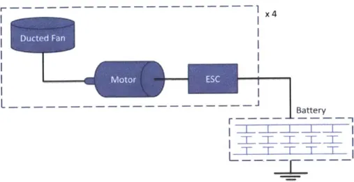
The current design of the Talaris hopper consists of the following parts: Ducted Fan 4 Aeronaut TF8000 Motor 4 Lehner 3060/10 HA ESC 4 Schulze future 40.161H Batteries 2S6P Tanic LiPo 7S 4500 30C Table 2.1 - Current configuration of the
gravity-reducing system of Talaris. These parts are arranged according to the following physical layout:
I x4 L -- ---- -L --- -. - - - - - - - -- --l Battery T l -L -L -L__L I "T T T T7 T
Figure 2.1 - Physical layout of the main components of the power-propulsion Talaris subsystems.
2.3. Configuration design problems
By restricting the system to EDI's made of connected COTS parts, the design of this subsystem of Talaris is an instance of the problem of "configuration design" (Stefik, 1995), also called "catalog design"
(Antonsson & Cagan, 2001). A more in-depth description than is given here of configuration design problems can be found in (G. Schreiber et al., 1999).
The goal of configuration design is to find an assembly of predefined components that satisfies all the requirements and constraints. Only components from the specified set can be used, and their possible interconnections or their physical disposition are also fixed a priori. Due to these restrictions,
configuration design is labeled "non-creative" design, meaning that human creativity is not required to perform the task. It is thus prone to be automated.
Set of available parts
The set of available components needs to be formally specified. There are various ways in which this specification can be done (B. J. Wielinga & A. T. Schreiber, 1997):
eThe set might be defined by an exhaustive enumeration. An example of such a definition would be "the resistors that can be used for the design are the models XX, XX3 and XX8 from
manufacturer Acme Inc." F
There might be parametric component types: An available component is then an instantiation of one such type, and is completely specified by its type and a set of parameters. The set of
available parts can be defined by explicitly enumerating the instantiations. For example, one such a definition would be "the design can use any of three resistors whose parameters are: 0.1
k a of resistance and 10 g of weight; I k of resistance and 5 g of weight; and 5.6 sn of resistance and 1 g of weight."
e instead of enumerating the available instantiations of component types, the available values for their parameters can be implicitly defined by constraints. An example would be: "only resistors weighting less than 10 g and with a resistance of less than 1Um can be used."
Ducted Fan
The ways to specify the set of available parts can thus range in a spectrum from totally explicit to totally implicit specification. In the totally explicit end of this spectrum is the definition of the set by using a parts database, which lists the available components and their characteristics. In the totally implicit end of the spectrum, the set is defined as the Cartesian product of the ranges of the parameters. Many of the design problems in this end of the spectrum have a solution that consists solely of an assignment of numerical values to design parameters. This specific case of configuration design is called parametric design (Motta & Zdrahal, 1996).
Relationships between requirements and design parameters. Estimation models.
Every design requirement is a relationship between design parameters that has to hold true in order for the design to be feasible or valid. Requirements can be classified as constructive or restrictive (Motta & Zdrahal, 1996): Constructive requirements are those that can be used to determine a parameter value as a function of others. Restrictive requirements, on the other hand, are those that can only be used to mark certain combinations of parameter values as invalid (inequalities are an example of restrictive requirements).
The designer can use the constructive requirements of a design problem to reduce its number of degrees of freedom. This simplifies the resolution of the problem in a far from trivial way, as design problems are prone to combinatorial explosion. When doing that, the parameters whose values aren't directly set by the designer, but rather calculated from other values, are called "functionally bound parameters." The parameters that are left to the control of the designer are called "key parameters," and form what is called the design vector.
Restrictive requirements are usually in the form "this parameter cannot exceed this value" or "that other parameter shall be bigger than this other value." The parameters that participate in such requirements are usually functionally bound parameters, and through this thesis are called "performance metrics."
How the final system will actually perform in each of those metrics is dependent on the system's design. Thus, in order to evaluate candidate designs, the values of the different metrics of interest must be estimated. This estimation is done by the use of mathematical models (analytical or numerical), or by the use of simulations (computer simulations, or physical analogs - as e.g. engineering models).
2.4. Review of some design-solving procedures
Having described configuration design problems, I now review three different methods to solve them. More comprehensive reviews with more detailed task analyses are published e.g. by (Motta & Zdrahal, 1996) and by (Chandrasekaran, 1990).
Process 1: Solve the inverse problem
The first method consists in solving the inverse problem, i.e. finding the design parameters that yield the desired performance metrics. In the general case, this will be an iterative process where system
requirements are expressed as constraints on the design parameters, and individual models relating only subsets of the design parameters are successively inversed.
The model used to evaluate the performance metrics of the system ("analysis model", or also "direct model") doesn't have to be analytically invertible: Numerical algorithms (mostly for continuous problems) can be used to solve them.
An example of design problem solved this way is the design by (Praveen et al., 2010) of a special kind of electric motor for space applications.
In the problem at hand, this approach is not only very complex, but also potentially undetermined, due to the implicit constraint that the design needs to be "feasible". In order to check the feasibility of a design, equations are required that can tell us if a set of design parameters is feasible or not. For that, it is not sufficient to check in the database, as the design vector in this case can hold continuous variables. Therefore mass models, cost models, and scaling relations are needed. Alas, these are not available for all components.
A possible way of overcoming this problem, commonly used in integer optimization, is that of relaxation. Relaxation consists in dropping the integrality constraint in one or more design variables, and adding reasonable empirical technological bounds. At that point, very efficient linear programming tools (e.g. Simplex) can be applied to solve for the optimal design variables, and then rounding strategies can be
used to obtain the best integer solution from that infeasible continuous solution. This general strategy is the basis of several integer optimization techniques such as branch and bound, and cutting planes. A survey of methods for integer optimization can be found in (Ehrgott & Gandibleux, 2003).
(Hanselman, 2006) discusses a disadvantage of using numerical algorithms to solve design problems in this way: The solution obtained is purely numerical. As no closed-form analytical relationship between
requirements and results is created, it is difficult to grasp the effects the various parameters produce in the solution. This grasping is essential to successfully solve most design problems.
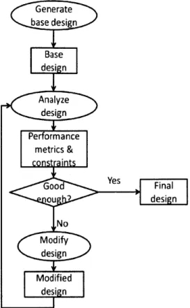
Process 2: Pick a base design and evolve it
The second design method is based on the selection of a base design that is subsequently refined. This method is known as Propose-Critique-Modify in the knowledge-engineering literature (Chandrasekaran, 1990; B. J. Wielinga & A. T. Schreiber, 1997).
The process starts with the selection of a fully-detailed base design. Not all of the final requirements of the system are met by the base design; its purpose is to act as a first guess. The design is then analyzed,
that is, its performance in the relevant areas is predicted theoretically, as well as its total cost. The requirements that aren't met by this analysis serve as a guide to change the design. This cycle of analysis, evaluation and redesign is repeated until a solution to the design problem at hand is found. A classical example of an automatic tool that uses this procedure is the expert system "VT" by (Marcus, Stout, & Mcdermott, 1987). It is specific to the domain of parametric design of elevators, and uses knowledge from that domain to guide the "modify" step.
The use of Microsoft ExcelT M
for programming analysis models, as part of this design process, is widespread. This could be understood by its huge availability. But also because of its non-algorithmic, data-centric, and visual model of computing: In effect, when developing analysis models in Excel, one has in front of their eyes the inputs, intermediate results, and outputs of all their computations. Changes in input values and formulas propagate immediately. With this very unique approach to computing, one can develop analysis software in a more agile and rapid way than can be achieved even with the use of the read-eval-print loop of interpreted languages.
Figure 2.2 - Flowchart for second design method: pick a base design and evolve it
When available, turnkey systems are a good selection for first pick of a base design, as they materialize designs that are guaranteed feasible, and close to meeting the system requirements. This was done in the Talaris project for the EDFS, leveraging the fact that many retailers sell complete EDF Systems and
provide some tested performance data of them. Other examples of projects doing it with COTS EDF Systems can be found in the literature (Shields et al., 2008; Y.-H. Yang, 1993).
Benefits and drawbacks
This design process is very popular because it facilitates a quick dive into detailed design, allows for prototyping, and does not require automatic design tools.
It can be seen as a discrete analog to the method of optimization by gradient descent. The search space here is the design space, and the cost function represents how far the current design is from meeting the requirements.
This analogy reveals some problems with using this method:
* Local minima: If the first guess isn't lucky, the final design could be a local minimum that still doesn't satisfy all of the requirements. (Zdrahal & Motta, 1996) demonstrate a "workaround" for this problem applicable to automatic designers. It is based on intelligently selecting various base designs from a database of historical cases and working from them. This approach is hardly manageable by human designers, though.
* Knowing the gradient: The difficulty of the inverse problem renders the "modification" step a knowledge-intensive task. To select the most appropriate direction to follow in the
multidimensional design space, the impact that changing each parameter would have on cost, mass, and other metrics, needs to be known. Of special importance for the performance of the process is an awareness of which subsystems have tight constraints imposed on them and which have looser requirements: The more difficult it is to design a specific subsystem, the more difficult it will be to succeed in modifying its design (Zdrahal & Motta, 1996).
* Knowing the domain constraints: The current technological boundary of the different
components must also be known, so as to avoid pushing across that barrier when changing a design parameter.
Those pieces of knowledge required to successfully follow this design method have chances of not being available. When such is the case, the "modify" task has to be reduced to a trial-and-error question: A set of differently modified designs is proposed at every iteration; they are analyzed; and all but the best-performing one are filtered.
Still, this is a very well suited process for designing complex systems in the cases in which there is no automatic search across the design space.
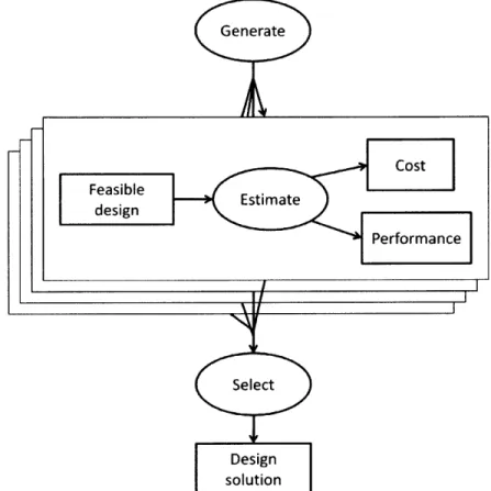
Process 3: Automatically generate and evaluate many designs
The third method relies on the automatic generation and evaluation of a large number of designs. The basis of this process is: Take every feasible design and analyze it to predict how much it would cost, and how it would perform in the metrics of interest. Then pick the best-performing with the lowest cost as the design solution for the system. The process is thus formed by three knowledge-intensive tasks: "generate", "estimate" or "analyze," and "select." Each task is explained in more detail in the following subsections.
"Generate" task
Except for some special uses of this design process, the generate task must avoid outputting infeasible designs; that is, designs that cannot possibly work properly or cannot be constructed. For some design problems, this is trivially done and not an issue. For others, it is necessary to resort to search strategies from artificial intelligence, such as the basic depth-first or breadth-first, or more advanced techniques including heuristics to make the search more efficient, such as A*.
The generate task can also be formulated as constraint satisfaction problem (CSP). Small CSPs can be solved by brute force, but in most cases specialized techniques such as backtracking are required. The backtracking approach begins by assigning an order to the variables. Then, similar to depth-first search, values are assigned to the variables, in order, one at a time. In other words, the partial solution is extended by incrementally instantiating variables. After each assignment, the constraints are evaluated, and if any are violated, the approach backtracks to the first variable for which there are other choices. Another choice is selected and the method continues on in this fashion until either a consistent solution is found, or all combinations of assignments have been explored.
Often, however, the violation is a result of a much earlier decision and a substantial amount of
backtracking is required to resolve the conflict. Dependency-directed backtracking (Stallman & Sussman, 1977) attempts to identify which variable is actually responsible for the conflict so that the solution process can directly backtrack to that variable.
Finally, some simple pre-processing techniques such as arc consistency can decrease the dimensionality of CSPs. For example, if design variables x and y are constrained to be equal, then the possible values for
x and y can be reduced to the intersection of their initial sets of possible values. An example of this constraint can be found in the Talaris design, as the motor is constrained to fit in the hub of the ducted fan.
Figure 2.3 - Flowchart of the third design method: Generate and analyze many designs, ad select among them.
Except for very simple systems, all possible designs cannot be analyzed in a reasonable time. In most cases, the set of possible designs is infinite. In some cases (such as the design of a wing profile), even the design vector for the system is of infinite dimension. Predetermined bounds are then added in the non-finite dimensions of the design vector. However, even in this case, full factorial enumeration of all possible combinations of design variables would be computationally impractical.
In order to deal with this problem, two strategies are followed: heuristics and abstractions. First, without any loss of optimality, efficient heuristic search algorithms can be used instead of naive enumeration in order to increase computational efficiency. However, it is not always trivial to find the right heuristics for a given problem, and furthermore, even with the right heuristics, search algorithms can only efficiently explore solution spaces up to a certain size.
Second, it is also possible to reduce the dimensionality of the model by abstracting components, i.e., by solving a simpler instance of the initial models and then filling in the missing details with a second problem solving effort. Note that this strategy implies - in general - the loss of optimality, since the set of optimal solutions to each of the subproblems may not form a globally optimal solution.
If neither heuristics not abstraction are enough, it will then be necessary to perform a stochastic exploration instead of an exhaustive exploration, using a Monte Carlo approach, or more sophisticated metaheuristic optimization algorithms such as genetic algorithms or simulated annealing. Obviously, since the tradespace is not exhaustively explored anymore, this third strategy also implies the loss of optimality.
Finally, note that prior to the execution of the "Generate" task, the problem can require the
construction of a database of existing parts (as was explained in Section 2.3). This task requires a lot of effort, and the resulting product can be very brittle if the task is not planned and executed properly. Chapters 4 and 6 go into more detail about this point.
"Estimate" task
This is the same analysis step that was used in the evolutionary design process: Its purpose is to derive estimates of the functionally bound parameters of the design from the values of the key parameters (the ones that form the design vector).
"Select" task
The former two steps of the design process can potentially (and they often do) output many solutions that are feasible and satisfy the problem requirements. Designs that satisfy those conditions are usually called valid designs. The "Select" (or "Optimize") task consists in the selection of one or more valid designs that best meet the requirements and preferences of the stakeholders.
There exists a preference binary relationship between design solutions: The stakeholders of the project, given two alternative valid designs, prefer one over the other (or do not care). This preference is usually based on how well a system built following each of the designs is estimated to perform, and on how much such systems would cost.
The Paieto front
Note that cost and performance are generally conflicting requirements. In other words, there won't be a single solution that happens to have, at the same time, both the lowest cost and the best performance. Indeed, design problems usually have multiple conflicting performance objectives, and therefore they do not have a unique solution.
There is a subset of the preference binary relationship between systems that is certain to hold, no matter what the problem is, and no matter what the stakeholders' goals are. It is the preference of Pareto-dominant solutions over Pareto-dominated solutions. A design X is said to be dominant (or non-dominated) if there isn't any other valid design that outperforms X in all objectives simultaneously. The set of non dominated designs is called the Pareto front or set of "efficient" solutions (Evans, 1984). Intuitively, in the case of cost and performance, the Pareto front contains the least costly design for each level of performance.
Selection within the Pareto font
How to select one of the designs on the Pareto front of cost vs. performance is a field of research in itself. It involves tasks such as the extraction of preference rules from the stakeholders, the creation of expressions to evaluate utility as a function of (multidimensional) performance, or the assessment of risks and their trade for profit. This matter, extensively treated by (Keeney & Raiffa, 1993), is out of the scope of this thesis work, but a part of it is worth mentioning:
In some problem cases, the different performance metrics of the system can be combined numerically to produce a single utility metric. This is what optimization tools and algorithms call the objective
function. It is a very powerful concept: In the cases in which the design problem is a case of parametric design, having a set objective function from the beginning reduces the whole design problem to a problem of numerical optimization. This is interesting because, being a more specific problem, numerical optimization has more mature tools for automatic resolution, and also because these tools can seamlessly handle design parameters whose domain is continuous.
In the general case, though, a numerical function of the performance metrics cannot describe the stakeholders' preferences, or cannot be discovered until alternative design solutions are presented to them. Without that scalar objective function, the selection step of this design process cannot be
automated by optimization algorithms. Techniques have been developed to address the cases in which the stakeholders' preferences cannot be articulated before the design process, but during or after it
(Evans, 1984). This gives interest to having the "Select" task consist solely of the selection of the Pareto front from the set of solutions. Another reason why this is interesting is discussed in the next sections, when Tradespace Exploration is presented.
2.5. Design problem simplification through abstraction.
For the three processes reviewed, as the complexity of the analysis models that need to be used increases, the design problem quickly becomes insurmountably hard.
The engineer with expertise in the design of the specific system at hand knows which design parameters affect performance and cost the most. With this knowledge, the design problem is greatly simplified by the method called iterative refinement:* Only the design parameters of greatest influence are taken into account initially. Then when a solution is found and selected, these parameters are considered fixed. A more detailed design can then be done concerning only the second-order parameters. If deemed necessary, the process can be repeated more times with the focus set on higher-order design parameters each time. Every time the design is refined in this way, it moves closer to an optimum solution, although with a law of diminishing returns. This design tactic is also called simplification by abstraction.
An additional benefit of simplifying a design problem through abstraction is that the analysis models of different subsystems usually become decoupled. When that happens, the design problem can be divided, and the process used to solve each subsystem can be tailored to its peculiarities. Before accepting a design at any abstraction level, it is important to check that the next-order parameters were rightfully discarded. For example, if some mass distribution was treated as if concentrated in one point, the first multipole moments of the distribution must be estimated and proven negligible.
These checks usually consist of assuring the values of the discarded parameters are much lower or much bigger than some property of the design being challenged.
For example, if the internal resistance of a battery is not relevant on first order, the detailed design of that battery can usually be decoupled from the rest of the system. The validity check for this very common assumption is simply derived from the second-order model, as seen in Equation (2.1).
Not to be confused with the aforementioned process of design by evolution, whose nature is also iterative. It is, though, orthogonal to this technique, which can be applied in the three design processes reviewed.
V = VO - IR = VO => IR &< VO => R & V0/I (2.1)
In the worst case, the validity check consists of reanalyzing the system using a more detailed model. Anyway, this is always a simple task in comparison to the task of designing.
Sources of abstraction knowledge. Tradespace exploration.
The first design process reviewed, solving the reverse problem, often sees simplifications "for convenience:" When some equation in the models cannot easily be solved, "offending" terms are hypothesized to be negligible. Validity checks are constructed for these hypotheses, and the resulting simplified equation solved. If the validity checks are then met, the simplification is successful: the solution is self-consistent.
Sensitivity analyses are a way to extract knowledge from the design tradespace.* They tell designers what parameters are the most important for a given application of a technology. This is done by taking partial derivatives of the performance metrics with respect to multiple design parameters. An example of sensitivity analysis as a means to do abstraction can be found in (Y.-P. Yang, H.-F. Liu, & J.-J. Liu, 2010).
Tradespace exploration is another technique to extract such knowledge.t Instead of explicitly computing the partial derivatives, a comprehensive sampling of configurations from the design space is analyzed and investigated. These are the same steps as those followed by the third design process reviewed: The same software tool can be used for both endeavors. Instead of performing a selection task, though, the generated designs are visualized, processed and analyzed in various ways. From them, the same
knowledge can be extracted as from sensitivity analysis, except in a "global" base: Sensitivity analysis results are local to the design vectors analyzed; they tell which design parameters can be neglected for each one of them. Tradespace exploration results tell the same thing for all the points of the design tradespace.
2.6. Overview of estimating methods
During the design process, a big number of times the designer is required to produce a quantitative estimation of some property in order to move forward. What property needs to be estimated can range from the total cost of the final system for a given design, to the strength of a bolt made of a given material. Whatever the property is, there are three very common methods to estimate it. In order of increasing precision, accuracy, and required effort, they are: analogy, parametric models, and detailed analysis (Apgar, Bearden, & Wong, 1999).
* Another use of sensitivity analysis is the concept of robust design. It consists of modeling the effect that the variability in some manufacturing and operating processes exert over the system performance. These processes are generally out of the reach of the designer, who then minimizes their impact by staying away from designs which are highly sensitive to them.
Another use of tradespace exploration is to learn heuristics about what makes a design perform well. For that, one might want to let pass infeasible designs: Sometimes a design that performs well but is infeasible can be made feasible by some little change that the designer didn't model.
Analogy
Analogy-based estimating of a property consists of selecting a sufficiently similar item for which detailed data on that property exists, and assuming the value under estimation would be the same. Small
adjustments are usually made to account for the differences between the object considered analogous and the object of interest. The more the differences, though, the less accurate the estimation would be. Unless the analogy is very gross, though, at least the correct order of magnitude for the value wanted should be obtained.
An example of estimation by analogy would be the use of look-up tables of measured properties. In this example, interpolating between two entries of the table would be the "small adjustment" mentioned above.
Parametric models
Parametric models (also called empirical models or scaling relations) establish functional relationships between two or more properties of an object. The property to estimate is then a function of those other properties, which are the parameters of the model.
Parametric models can be generated by looking at a set of past examples (the more sample points, the better) and fitting a statistical model to the data (hence their name empirical). Tradespace exploration of parts catalogs can also be used to generate empirical models for the technological state of the art of the parts.
Detailed analysis
Estimation by detailed analysis derives the property under scrutiny from first principles and the values of other known properties. It requires a level of detail of the object under analysis that might not be available, as well as a sound understanding of the principles that determine the value of the property of interest.
For example, to estimate the aerodynamic parameters of a ducted fan, one can proceed from the precise geometry of the blades. This detailed geometry information isn't made available by vendors of COTS ducted fans. Also, most properties of an electric motor can be derived from the knowledge of its internal geometry. This data is rarely published by vendors or manufacturers. Chapter 3 presents other estimation methods for ducted fans and BLDC motors that are, in this sense, more useful than detailed analysis.
The benefit of using this method is increased in the cases in which one or more of the parameters of the analyzed object are under the control of the designer. When that is the case, they can be adjusted to optimize the estimated metric.
2.7. Automatic design tools
Automatic design tools are computational tools that automate part or all of the design process, i.e. any subset of the tasks described in Section 2.4. These tools can be domain-specific, or domain-generic. Their differences are common to all alternative sets of technologies which differ in flexibility: Generic tools are more costly to develop, and in exchange they have higher chances of being applicable to the
specific design problem at hand. A characteristic of generic-domain tools that is very attractive for the Talaris EDF System design problem is that their flexibility easily accommodates a rapid-prototyping process: The formal description of the problem is easily changed and refined iteratively.
As was explained in Section 2.5, the third design-solving process presented in Section 2.4 (generating many design and selecting the Pareto front) is highly synergistic with the process of tradespace
exploration. As a consequence, there is commonality in the tools used for both. It is important that such tools be domain-generic, though, instead of tailored for a specific design problem. This is because the knowledge products of tradespace exploration can make a design problem solvable by one of the other two, "simpler," procedures explained (namely evolving a base design and solving the inverse problem). If that happens and the tools are not domain-dependent, they still are useful, for they can be applied to other problems.
2.8. Rules engines
A rules engine (also called production rule system or production system) is a software development tool that has seen extensive use in the field of business management software (where they are known as "business rules engines"). They form part of A.I.'s branch called Knowledge Engineering, and their purpose is to ease automatic reasoning over big datasets.
Rules engines work on a database referred to as "facts base," or "working memory." When the rules engine is executed, the facts (database records) of this database are filtered using very expressive pattern-matching filters. The programmer sets ups the filters, and writes actions that are to be executed on each successful match. The combination of a filter and its associated actions is called a "rule," from which the system gets its name. The power of the system that uses the rules engine is realized when the rules' actions modify the facts base. As new facts are thus added to the working memory, the firing of further rules is triggered, and reasonings can in this way be chained. This is explained in detail below. Traditionally, the facts base, the filters and their actions are written in a special-purpose programming language. The de-facto standard rules language is called CLIPS. Its syntax and semantics are also detailed next.
Parts and functioning of a rules engine
Rule-based systems are a very powerful way of storing and manipulating knowledge in the form of logical rules. These rules follow the general form "If X then Y", where:
* X is called the left hand side (LHS) of the rule, and contains a set of conditions;
e Y is called the right-hand side (RHS) of the rule, and contains a set of actions to be executed should all the conditions in X be true.
A rule-based system consists of four components:
* A rule base, which contains the knowledge in the form of rules.
e The (temporary) working memory, sometimes called the fact base, which contains the input