The Design and Development of an Educational Controls Laboratory: Electromechanical Module, Control Software, and Graphical User Interface
by
Richard Dick Wang
Bachelor of ScienceinAeronautics and Astronautics University of Washington (1993)
Submitted to the
Department of Mechanical Engineering
inpartial fulfillment of the requirements for the degree of Master of Science in Mechanical Engineering
at the
Massachusetts Institute of Technology June 1995
© 1995 Massachusetts Institute of Technology All Rights Reserved
ffigna~re~Auilim~~~~~~~~~~~~~~~~~~~~~~~
IV
Departme~f
Mechanical EngineeringMay 19, 1995 Certified bY~---r>_. ---7"::J
,.,...---'1-+---Steven Dubowsky Thesis Supervisor Accepted by _ Ain A. Sonin Chairman, Departmental Graduate Committee
i.~;~.SSA(:l-!USETTSII..JSTITUTE OF TECHNOLOGY
AUG
311995
,':'r' -:.
The Design and Development of an Educational Controls Laboratory: Electromechanical Module, Control Software, and Graphical User Interface
Submitted to the
Department of Mechanical Engineering on May 22, 1995
in partial fulfillment of the requirements for the degree of Master of Science in Mechanical Engineering
by
Richard Dick Wang Abstract
Hands-on experience plays an important role in an educational System
Dynamics and Controls curriculum. At the Massachusetts Institute of
Technology, the Department of Mechanical Engineering offers a series of undergraduate courses in the area of system dynamics and controls, including one that contains a laboratory component. The current Controls System Laboratory has been in service for ten years with little upgrading or modernization. The worn equipment and out dated technology has created a need for a new laboratory.
The Department of Mechanical Engineering at the Massachusetts Institute of Technology launched a study into redeveloping the controls system laboratory. A team of two masters students was supervised by a faculty member in the department to carry out this project.
As the result of this 18-month study, a modular and flexible laboratory prototype set-up was designed, fabricated, and tested. The prototype system uses commercially available hardware and software, plus in-house modifications and tailoring, to build a user friendly and educationally effective System Dynamics and Controls Laboratory workstation.
This thesis focuses on the design and fabrication of an electromechanical experiment module, and the creation of the fundamental software programs for the new laboratory. The overall software structure design, real-time control, and the graphical user interface are also documented.
Thesis Supervisor: Dr. Steven Dubowsky
To my Parents Alice and David
Acknowledgments
I would like to express my gratitude to my advisor, Professor Steven Dubowsky, for giving me this wonderful opportunity of my life. I deeply appreciate his invaluable direction and advice throughout this project.
I am also grateful to Professor Nam Suh, Professor Boris Mikic, and the Department of Mechanical Engineering at MIT for their support of this project.
To my project partners: Michele Tesciuba, Jason Hintersteiner, and German Soto; it has been my pleasure working with you in achieving this success. I would especially like to thank Michele for making this project truly a learning experience for me, and Jason for his encouragement and witty ideas.
I thank my groupmates Craig Sunada, Dinos Mavroidis, Peng-yun Gu, Tom Corrigan, Nathan Rutman, Jeff Cole, Bob Beretta, Kazuya Yoshida, and my officemates Ssu-Hsin Yu and Rienk Bakker, for their company and words of advice.
My special thanks to Norman Berube, who taught me everything I know about machining.
I hereby also recognize Thomson Industries, Inc.'s generous donation of a linear slide table, model 2EB-08-FTB-F L30.
To the following people who made my life here in MIT so much more fulfilling...
I would like to thank my co-Co-Co's in the Hong Kong Student Society of MIT: Julian Lee, Preston Li, Ernie Yeh, Calvin Yuen, and Kayan Wong, for working together with me in making HKSS 94-95 such as beautiful year to
remember. Also, thanks to all the members who's enthusiasm is
immeasurable. Without them, it would have been impossible for
Intercollegiate Hong Kong Week '95 to take flight.
My heartfelt thanks to the brothers and sisters in Hong Kong Student Bible Studies, who's love, care, and prayer support carried me through the toughest times in my two year stay in MIT. Especially to my cell groupmates, Kai-Pak Chan and Kinhong Kan: your open ears and understanding hearts are priceless.
To my two apartmentmates, Doug Chan and Ellen Hazen: Thank you for being so wonderful. And, how can I forget, Courtney the most lovely cat I know.
Thanks to all my fellow DJ's in the radio show Touch of Hong Kong, who's dedication to the show gave our imaginations a chance to become
realities. I simply just cannot describe how much fun and excitement I had in the studio.
To all my fellow mid-night snackers I thank - Jerome Lui for
organizing the events; Albert Wong for providing transportation; and Tony Wong for constantly challenging my "Black Hole" title.
I must thank my "soupers", Phoebe Fu, Vinci Leung, Jenny Lee, and Vivian Cheung, who provided me, the "soupee", the essential food group
-soups - to survive the countless number of all-nighters in MIT.
To my many friends in MIT, Jocelyn Chen, Andy Shum, Felix Lo, Elaine Yiu, King-Chung Yu, Zachary Lee, and Levina Ha: Thanks for sharing this memorable time with me.
To my two best friends in MIT - Bernard Wong and Patrick Leung.
Knowing you is definitely one of the best things that happened to me. The long talks at night, the fun we have in HKGSS, and trips we took together, keep us so close even when we are thousands of miles apart.
My love and thanks go to my Parents, for their unconditional love and consistent support, unmatched by any persons in the world. I would also like to thank Derek, for teaching me how to be an older brother, and making my life so much more interesting.
Most importantly, I would like to thank the almighty God, who has revealed Himself to me and given me the greatest love of all.
Table of Contents
CHAPTER 1 INTRODUCTION ... 11
BACKGROUND ... 11
RESULT OF THIS PROJECT ... ... 12
PURPOSE OF THIS THESIS... 12
OUTLINE OF THIS THESIS ... 13
CHAPTER 2 INTELLECTUAL REQUIREMENTS AND DESIGN OBJECTIVES...15
INTRODUCTION ... ... 15
PREPARATORY WORK... 16
Interviews with the Faculty...16
Literature Review ... ... 19
Student Interaction... 20
INTELLECTUAL REQUIREMENTS FOR THE LABORATORY ... ... 22
DESIGN OBJECTIVES ... 27
SUMMARY ... ... 28
CHAPTER 3 OVERALL DESIGN OF THE NEW SYSTEM DYNAMICS AND CONTROLS LABORATORY ... 29
INTRODUCTION ... 29
OVERALL DESIGN SCHEME ... 29
ORGANIZATION OF THE COURSE ... 30
Class Schedule... ... 30
Class Size and Number of Stations... 30
Teaching Assistant Schedule... 31
Method of Communication ... 31
PHYSICAL SET-UP DESIGN ... 32
Overall Picture... 32
Modular Design Approach... ... 32
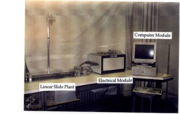
Computer Module ... ... 35
Electrical Module ... 36
Physical Modules ... 37
SOFTWARE DESIGN AND SELECTION... 38
WORKSTATION DESIGN ... 39
LABORATORY FLOOR PLAN ... 40
SUMMARY ... ... 40
CHAPTER 4 ELECTROMECHANICAL MODULE - THE LINEAR SLIDE TABLE...42
INTRODUCTION ... ... 42
SELECTION OF THE ELECTROMECHANICAL MODULE... 42
DYNAMICS OF THE LINEAR SLIDE TABLE ... 43
DESIGN AND FABRICATION OF THE ELECTROMECHANICAL MODULE ... ... 44
COMPATIBLITY WITH THE ELECTRICAL AND COMPUTER MODULE ... 52
Electrical Module Calibration ... ... ... 52
Computer Module Modification ... 53
PERFORMANCE SPECIFICATIONS OF THE LINEAR SLIDE MODULE... 53
MAINTENANCE FOR THE LINEAR SLIDE MODULE... 54
Lubrication of Ball Screw Assembly.. ... 54
Calibration of Servo Amplifier... 54
COST BREAKDOWN OF THE LINEAR SLIDE SYSTEM... 56
SUMMARY ... ... 56
CHAPTER 5 DEVELOPMENT OF REAL-TIME CONTROL SOFTWARE ... 57
INTRODUCTION ... ... 57
RTC SOFTWARE DESIGN CONCEPT ... 58
The RTC Big Picture... 58
PROGRAMMING THE I/O BOARDS... 60
General Programming for DATEL PC-412A ... 60
General Programming for US Digital PC7166 ... 62
General Programming for Video Blaster SE O100... 63
RTC BUILDING BLOCKS ... 64
Data Acquisition ... 65
Controllers... 68
Command Signal Output... 69
Tim er... ... 70
Reference Signal ... 75
Inp ut... ... 77
Output ... 78
SUMMARY ... ... 79
CHAPTER 6 DEVELOPMENT OF GRAPHICAL USER INTERFACE... 80
INTRODUCTION ... ... 80
OVERVIEW OF GUI FUNCTIONS ... 81
THE GUI ARCHITECTURE... 82
MOSAIC AND THE WORLD WIDE WEB ... 83
MATLAB NOTEBOOK SUITE / MICROSOFT WORD... 84
Laboratory Report Template... 84
How to Create an Laboratory Report Template... ... ... 85
MATLAB GUI ... 85
MATLAB GUI Architecture ... 85
How is a MATLAB GUI Page Written? ... 87
Parameter Input Group ... . 88
Analysis Group... ... 90
Real-Time Control Group... ... 94
DEVELOPING NEW MATLAB GUI SETS ... 96
SUMMARY ... ... 96
CHAPTER 7 STUDENT TESTING ... 98
INTRODUCTION ... 98 STUDENT TESTING... ... 98 Demographics of students ... ... 98 Test Method... 99 Survey ... ... 99 R esults ... ... ... ... 100 SUGGESTED IMPROVEMENTS...102
Graphical User Interface...102
Electromechanical Module...102
SUMMARY ... ... 103
CHAPTER 8 CONCLUSION... 104
CONTRIBUTION OF THIS WORK...104
IMPACT OF THIS PROJECT ON FUTURE LABORATORY COURSE DEVELOPMENTS ...105
BIBLIOGRAPHY ... ... 106
APPENDIX A INTERVIEW CONTACTS ... ... 109
APPENDIX B CLASS ENROLLMENT HISTORY ... 111
APPENDIX C PROPOSED COURSE SCHEDULE ... 112
APPENDIX E COST BREAKDOWN OF COMPUTER MODULE ... 116
APPENDIX F DYNAMICS OF LINEAR SLIDE TABLE SYSTEM...117
APPENDIX G A SAMPLE OF LABORATORY HANDOUT AND REPORT ... 121
List of Figures
Figure 1. A Current Controls System Laboratory Workstation... ... 14
Figure 2. Primary Purpose of the Laboratory... 23
Figure 3. Overall Physical Set-up Design... 33
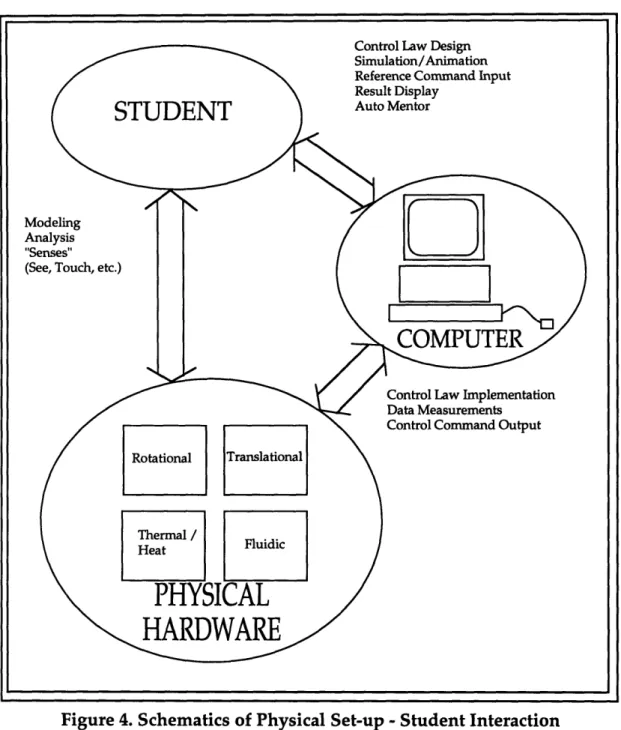
Figure 4. Schematics of Physical Set-up - Student Interaction ... 34
Figure 5. Workstation Layout Design ... 40
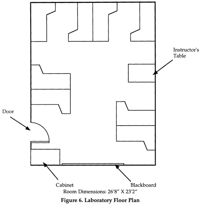
Figure 6. Laboratory Floor Plan... ... 41
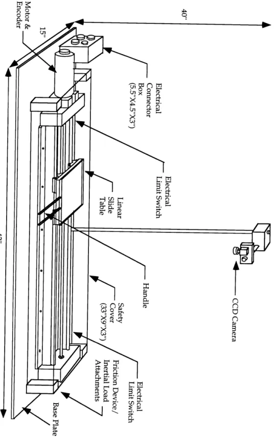
Figure 7. Photograph of Electromechanical Module... 45
Figure 8. Overview of the Linear Slide Table Plant... ... 46
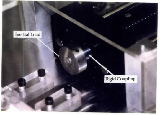
Figure 9. Rigid Coupling and Inertial Load... 48
Figure 10. Friction Device... ... 49
Figure 11. CCD Cam era and M ount... 50
Figure 12. Electrical Switch Circuit Diagram... 51
Figure 13. Circuit Diagram for Servo Amplifier Calibration... ... 55
Figure 14. Schematic of Software Communication Architecture... 57
Figure 15. The RTC "Big Picture" ... 59
Figure 16. Schematic of A/D Building Block... 66
Figure 17. Internal Structure of A/D Building Block... 67
Figure 18. Schematic of Encoder Block... 68
Figure 19. Schematic of the Open Loop Controller Block ... 68
Figure 20. Schematic of PID-Controller Building Block... ... 69
Figure 21. Schematic of D/A Building Block... 70
Figure 22. Schematic of the Timer Building Block... ... 73
Figure 23. Schematic of the Vision System Building Block... ... 76
Figure 24. Schematic of the Configuration Block... ... 77
Figure 25. Schematic of the Graphical User Interface Block... ... 78
Figure 26. Schematic of the Output Block... 79
Figure 27. Schematic of Software Communication Architecture... 80
Figure 28. Functions of the Graphical User Interface Software ... 81
Figure 29. GUI Architecture of the Laboratory... ... ... 83
Figure 30. M ATLAB GUI Architecture... 86
Figure 31. Typical MATLAB GUI Menu Page ... 86
Figure 32. A Typical MATLAB GUI Script... ... ... 87
Figure 33. Param eter Input Group... 88
Figure 34. Analysis Group ... ... 90
Figure 35. Sample Output from Control Analysis Function... 91
Figure 36. Typical Simulink Block Diagram... 92
Figure 37. Typical Frame of Animation ... ... 92
Figure 38. Typical Simulation Data Display... 93
Figure 39. Real-Time Control Group ... 94
Figure 40. Typical Experimental Data Display... ... 95
Figure 41. Volunteer Student Demographics by Year... ... 98
Figure 42. Survey Result ... ... 100
Figure 43. Survey Result ... ... ... 100
Figure 44. Survey Result ... 101
Figure 45. Schematic of the Linear Slide Table...117
Figure 46. Typical Velocity Response to Step Input... .. 118
Figure 47. Typical Experimental Open Loop Step Velocity Response ... 118
Figure 48. Typical Friction Value Determination Plot (without friction device) ... 119
Figure 49. Velocity Response to Step Input (with additional inertial load)...119
Figure 50. Typical Frictional Value Determination Plot (with friction device)...120
LIST OF TABLES
Table 1. Cost Breakdown of the Electromechanical Module... 56
Table 2. M em ory M ap for PC-412A ... ... 61
Table 3. Memory Map for US Digital PC7166... 63
Table 4. Functions of SE100 A PI... 64
Table 5. RTC Building Blocks... 65
Table 6. Summary of the Counter Functions and Mode Settings... ... 72
Table 7. Reference Input Param eters... ... 89
Table 8. Class Enrollment History for Course 2.14 (Control System Principles) ... 111
Chapter 1 Introduction
Background
System dynamics and controls is an integral part of a modern undergraduate education curriculum in the mechanical engineering discipline. In 1990, 72.5% of the mechanical engineering departments in the United States have at least one required course with a significant focus on controls [Feliachi 1991].
It is widely recognized that a practical laboratory course in system dynamics and controls is essential for an effective education program. Yet, only 35% of electrical and mechanical engineering departments in the United States offer undergraduate controls laboratories [Feliachi 1991].
At the Massachusetts Institute of Technology, the Department of Mechanical Engineering offers a series of undergraduate courses in the area of system dynamics and controls, including one that contains a laboratory component. The current Controls System Laboratory was developed in the mid-1980's and has been in service for ten years with little upgrading or modernization. With an average of approximately 160 students per year, the controls system laboratory has been under intensive usage and much of the equipment is worn out. Moreover, the technology used in the current
laboratory is quite dated. For example, in the industrial world today,
microprocessor-based real-time control is a standard. In the current
laboratory, however, the students still build their controllers by "patching" an analog computer. With the lack of renovation, heavy wear and tear, and the employment of old technology, the current controls system laboratory has lost much of its educational value. Both the faculty and the students have expressed the need for substantial laboratory improvement.
In light of the existing situation, during the Fall Semester of 1993, the Department of Mechanical Engineering at the Massachusetts Institute of Technology launched a study into redeveloping the controls system laboratory. It is anticipated that this project will not only bring in
state-of-the-art technologies to the system dynamics and controls curriculum at MIT, but will also serve as a model for engineering schools in other universities as they develop similar laboratories. A team of two masters students was supervised by a faculty member in the department to carry out this project. The team surveyed the faculty and reviewed the intellectual needs of the laboratory. Literature search and site visits to other universities' controls system laboratories were conducted to investigate the approach of other engineering schools. In addition, the two graduate students became the laboratory teaching assistants to learn, first hand, about the strengths and short comings of the current laboratory. The team was later joined by two undergraduate thesis students from the Mechanical Engineering Department to assist the overall progress by specializing in developing certain areas of the project.
Result of this Project
As the result of this two year study, a modular and flexible laboratory prototype set-up was designed, fabricated, and tested. The prototype system uses commercially available hardware and software, plus in-house modifications and tailoring, to build a user friendly and educationally effective System Dynamics and Controls Laboratory workstation. It is hoped that this prototype can serve as a model for future development of similar types of laboratories at other engineering schools. Moreover, the modular design approach employed in the creation of this prototype is adaptable to develop educational laboratories in other engineering disciplines.
Purpose of this Thesis
This thesis, in conjunction with the master's thesis of M. Tesciuba [Tesciuba, 1995], and the bachelor's theses of J. Hintersteiner [Hintersteiner, 1995] and G. Soto [Soto, 1995], documents the design and development of a new System Dynamics and Controls Laboratory prototype set up. These four theses combined outline the important intellectual content of the system dynamics and controls courses taught in MIT and the overall design of the new laboratory. They cover the technical details regarding each component of the whole laboratory system, propose a laboratory schedule, and present
particular, the master's thesis for M. Tesciuba focuses on the electrical and the fluid tank module, as well as the physical layout of the new controls system laboratory floor plan and workstation set-up. The bachelor's thesis written by J. Hintersteiner concentrates on the development of the network interface of the laboratory computer system with the MIT school-wide computer network, Athena. It also covers some aspects of developing the real-time control algorithms for the physical plants. The bachelor's thesis by G. Soto specifies the design and technical descriptions for the fluid tank physical module.
An emphasis of this thesis is on the design and construction of a physical experiment module. Specifically, the design of a ball screw driven linear slide table system design, along with an evaluation of its performance, is documented in this thesis. Another emphasis of this thesis is the creation of the fundamental software programs for the project. The overall software structure design, the fundamental software building blocks for running real-time control, and the graphical user interface are described in detail. Some of the material contained in this thesis is taken from the companion theses [Hintersteiner, 1995] [Soto, 1995] [Tesciuba, 1995] and presented here for clarity.
Outline of this Thesis
This thesis is organized into eight chapters. This chapter introduces background and the motivation of the project, as well as a general overview of the thesis itself.
The second chapter describes the preparatory work that led to the formulation of the intellectual requirements and design objectives of the new system.
Chapter 3 presents the overall system design and general descriptions for each component, including the Computer Module, the Electrical Module, and the two Physical Modules. An overview of software configuration for the system is also introduced. Furthermore, logistics such as a proposed class schedule, course enrollment size, laboratory workstation layout, and a floor plan are included.
Chapter 4 documents the design of the linear slide module in detail. It also summarizes the performance specifications of the linear slide system, and presents maintenance procedures and a cost breakdown.
The main components of the real-time control software are detailed in Chapter 5. It illustrates the real-time control software architecture and the building block design approach which allows future developers to quickly set up the necessary supporting software for future physical plants.
Chapter 6 focuses on the development of user interface software. General descriptions on the user interface organizations as well as in depth discussions on creating graphical user interface applications are covered.
Chapter 7 summarizes the results of student testing of the new set up and improvement suggestions.
Chapter 8 is the conclusion chapter. It reviews the contributions made by this project and explores the potential impact on future laboratories development.
A series of comprehensive appendices provide coverage on the details of the work, such as logistics of the future course and component specifications for the hardware, as well as a cost breakdown of the prototype set-up modules and sample laboratory exercise handouts.
Chapter 2 Intellectual Requirements and
Design Objectives
Introduction
Prior to actually designing the new controls system laboratory, the project team had to investigate the needs of the clients. The two primary clients of this project are the faculty of the Mechanical Engineering Department at MIT and the students. The team started the project by carefully reviewing the materials taught in the course lecture and laboratory. At the same time, the team individually interviewed system dynamics and controls faculty members in Mechanical Engineering Department at MIT to obtain their views on the development of the new laboratory. Later, the team also had various opportunities to meet with faculty members outside the Mechanical Engineering Department and outside MIT to discuss contemporary issues in developing educational system dynamics and controls laboratories. An extensive literature search was also conducted to understand the current efforts of other engineering schools developing similar laboratories.
To better understand the need of the students, the two graduate members of the team were assigned the positions of laboratory teaching assistants for three consecutive regular semesters (Spring 94, Fall 94, and Spring 95). This teaching opportunity allowed the team to find out, first hand, the strengths and weaknesses of the current Controls Systems Laboratory from active interactions with the students.
The preparatory work led to formulating the intellectual requirements and defining the design objectives of the new System Dynamics and Controls Laboratory. This chapter documented the results of the faculty interviews, literature search, and student interactions. At the end of this chapter, the intellectual requirements and design objectives of the laboratory are presented.
Preparatory Work
Interviews with the Faculty
During the first stage of the project, the primary effort of the team was to gather information on the requirements of the new laboratory, which would define the scope of the project. The first step of achieving this task was done by interviewing professors knowledgeable in this area.
Altogether, a total of 23 professors were interviewed in person. Among these, 17 were MIT Mechanical Engineering faculty, one was an MIT professor from Ocean Engineering Department, and five of them were non-MIT professors who have expertise in system dynamics and controls education at other universities. In addition, three more professors from other universities were contacted by electronic mail and by telephone (see Appendix A).
The professors contacted had a common general view on what the new System Dynamics and Controls Laboratory should provide. In their opinion, the laboratory should be a place where the students can enhance their understanding in a physical sense such as by seeing and touching of the materials they have learned in the course lectures. However, their ideas on the means to achieve this goal were quite diverse. The following paragraphs summarize the main issues raised during the interviews. These main issues can be categorized into two groups: (1) Issues regarding the physical set-ups of the laboratory; (2) Issues regarding to the running of the laboratory course. Summary of the Interviews
The following issues are in regard to the physical set-ups:
Digital Equipment vs. Analog Equipment
The choice of using digital equipment in the new laboratory or continue using analog equipment was discussed. The use of digital equipment will yield higher quality results. However, the digital aspects of control should be "masked", i.e. the control experiments should appear as if they were operating in the continuous time domain. On the other hand, students can benefit from preserving analog computers in the laboratory curriculum since they are a good
way to implement block diagrams. Moreover, the importance of hands-on experiments in analog circuits, particularly, Op-Amp circuit building, was acknowledged. The addition of Op-Amp experiments allow students to be exposed to lead/lag compensator hardware building blocks.
Easy Interfacing
Professors recognized the need for easy interfacing with the laboratory set-ups (easy input and easy-to-see output) so that the students can concentrate their efforts in absorbing and understanding the important concepts instead of devoting excessive time getting the system to work. For example, the Macintosh style (use of windows, icons, click and select features with a mouse, etc.) graphical user interface was suggested.
Variety of Physical Set-ups
A popular idea among the professors was to include a number of different set-ups from various Mechanical Engineering disciplines, such as vibration, fluids, thermodynamics, and heat transfer, in addition to the traditional translation and rotation dynamics models in the laboratory. These physical systems can also be used for illustrating the modeling concepts presented in the introductory level system modeling course.
Reality in the Laboratory
Some professors mentioned that the material presented in the lectures is often too simplistic (for instance, noise and friction are ignored), and the laboratory should serve to give the students a taste of
reality. Moreover, the use of actual engineering systems from
industries as laboratory equipment was suggested to allow students becoming familiar with industry standards as well as keeping up with
the latest technology.
Lego-Like System
Using a "Lego-Like" system design concept in the laboratory physical set-ups can enhance the hardware's modularity. For example, a laboratory station set-up which allows the students to place sensors of various qualities in different locations can give the students a feeling of both sensor noise and observability.
Up-to-date Equipment
The laboratory should be set up with the most up-to-date and widely used equipment, both in hardware and software.
The following issues are in regard to the running of the laboratory course:
Simulations
The idea of pre-laboratory simulations was discussed. The
primary advantage for pre-laboratory simulations is to give the students the opportunity to exercise their modeling skills with the use of computer software. Simulation is also a good way for the students to predict the response and compare the theory to the practical results. Moreover, carrying out pre-laboratory simulations will allow the students to get familiar with the experiments prior to class time, and therefore to learn more when they carry out the laboratory experiments.
In-Class Demonstration
Once a week, ten-minute lecture demonstrations with robust and reliable physical systems was suggested. It was also suggested that set-ups in the new System Dynamics and Controls Laboratory be used for this purpose.
2 Hours-per-week versus "Live-in" Laboratory
The issue of how much time each laboratory session should take was considered. The "live-in" type of laboratory requires the students to spend about 8 hours per week, and it will be an "open-laboratory" format (i.e. the student can go in at any time of the day). This laboratory format would allow the students to get in-depth experience in controls, and more topics could be illustrated in the laboratory. The current 2-hour-per-week format requires the complexity of the experiments to be minimized so that the laboratory takes approximately 2 hours per week to finish.
Rotation Lab Set-ups
A new laboratory teaching philosophy, which involves having various groups of students work on different set-ups every week, was discussed. The benefit of this organization is to allow the students to work on a greater variety of systems without investing a large sum of
money to build several identical set-ups. On the other hand, giving the students too many systems to work on may prevent them from fully understanding any particular set-up.
Design Project
The issue of having a design project at the end of the term was raised. The design project could allow the students to sum up and apply the concepts they learned in class, but it could also possibly lead to a great deal of paper work and become a burden to the learning process.
Literature Review
Extensive literature searches on topics related to the development of educational system dynamics and controls laboratories was conducted in the
early stage of the project. The primary sources of the literature were
proceedings from American Control Conferences from 1988, 1991, and 1993, in which over two dozen papers were published on this topic. Other papers were obtained through private contacts with professors at other universities and engineers in the industry. The literature search provided the project team with a general overview of how other engineering schools approach the challenge of designing an effective educational controls laboratory. Some general observations were made from the literature search and they are listed as follows:
* Digital computers are commonly used for data acquisition, real time control, and simulations. They can also replace many devices such as oscilloscopes, function generators, etc. [Baish et al, 1988] [Huang et al, 1993] [Kopacek et al, 1988] [Kulakowski, 1988] [Vagners, 1993]
* Flexible laboratory up design are widely adopted. This makes the set-up capable of controlling a wide variety of processes and physical plants that could be of interest to students of many disciplines. [Baish et al, 1988] [Bonner et al, 1988] [Erickson, 1993] [Kulakowski, 1988] [Levine et al, 1993] [McDermott et al, 1988]
* The content of the laboratory should provide connection to reality, thus giving the curriculum relevance and reinforcement to the academic material by the need to actually apply it to achieve an experimental objective. [Auslander et al, 1988]
* A quote on defining the criteria for judging a physical system for a controls laboratory is found: "control objectives must be safe, reasonably fast but not too fast, have some 'real world' irregularities, but not so much that control theory never works, not break too often, and not cost too much."
[Auslander et al, 1988]
* Extensive variety of software (both commercial and customized) for simulation, analysis, and visualization are used. [Astrom, 1991] [Bodruzzaman, 1992] [Cheok et al, 1993] [Das et al, 1993] [Eaton, 1994] [Feliachi et al, 1991] [Franklin et al, 1988] [Huang et al, 1993] [Levine et al, 1993] [Schaufelberger, 1988] [Vagners,1993]
* The laboratory should place emphasis on hands-on experience. [Bonner et al, 1988]
* Students are encouraged to work in groups rather than individually. [Franklin et al, 1988]
Student Interaction
Since the ultimate beneficiary of this laboratory will be the students, their views on the current system dynamics and controls laboratory in the MIT Mechanical Engineering Department played an influential role in the team's subsequent design decisions on the new laboratory. Recognizing this fact, the two graduate students on the project team were assigned the positions of laboratory teaching assistants for the existing System Dynamics and Controls Laboratory. This teaching experience enabled the two graduate students to have frequent opportunities to interact with the students, through which the strengths and weaknesses of the current laboratory were better understood.
Student Demographics
During the three semesters of Spring 1994, Fall 1994, and Spring 1995, a total of 178 students were enrolled in the laboratory (Appendix B). The majority of the enrollments were juniors and seniors from the Mechanical Engineering Department. However, a handful of sophomores and graduate students were also part of the composition. In addition, small numbers of students from other departments, such as Electrical Engineering and Sloan
Business School, contributed to the total enrollment. Since the new laboratory is targeted mainly for upperclassmen in the Mechanical Engineering Department, the focus of this section will be on this group.
Observations from Student Interactions
From the interactions with the students in the current laboratory, the following strengths and weaknesses were observed.
Strengths
Robust Equipment
The current laboratory equipment can be qualified as robust, when one considers what the equipment has gone through in the past ten years - intensive usage by over a thousand students and relatively little maintenance - coupled with the fact that it is still in operational condition today.
Safety
Even under intensive usage of many students, no accident involving physical injury occurred in the laboratory in the past three terms (Spring 1994, Fall 1994, Spring 1995).
Provides Sufficient Hands-on Experience
The students seem to appreciate the hands-on experience provided by the laboratory set-ups. The students are able to employ their senses when they see the motor spin or when they use their hands to turn the motor and feel the spring like effect from a P-controller.
Compact Size
The physical plant has a relatively compact size - the whole
system can be placed on a 8' by 2.5' work bench. This permits the accommodation of several workstations and over a dozen students to work in the laboratory room at the same time.
Weaknesses
Most upperclassmen, by the time they enroll in this laboratory, have theoretical and/or practical experience with analog circuits such as operational amplifier circuits. In general, however, their transition to the usage of the Comdyna analog computer does not prove to be a smooth one. Students spend significant amount of time learning to operate the analog computer. This overhead is a main cause of student frustration in the laboratory and consumes valuable laboratory time.
Lack of interesting experimental set-ups
Even though the current physical plant (motor - inertial load) serves the educational purpose, it lacks fun and excitement.
Too many components in the set-up
The existing set-up consists of five components per workstations: a Comdyna analog computer, a motor/inertial load plant, a voltage-to-current amplifier, an oscilloscope, and a function
generator. The cables connecting these components can become
unnecessarily complicated at times and thus diminish the educational value of the laboratory.
Equipment unable to perform the necessary tasks
In one of the experiments, the students are asked to apply a constant frictional torque to the system. However, there is no device in the physical set-up which allows the students to apply such a disturbance in a consistent manner. Another example is, in more than one instance, the analog computers are required to output a calculated control signal greater than its maximum voltage output, thus causing the system to be overloaded and sometimes become unstable.
The new laboratory design aims to preserve the strengths of the current laboratory set-up and combat the weaknesses.
Intellectual Requirements for the Laboratory
At the end of the first stage, the project team evaluated the results gathered from the preparatory work described above, and formulated the intellectual requirements for the new System Dynamics and Controls
Laboratory. The intellectual requirements served as the measurement standard in the team's design decisions as the project progressed. In other words, this intellectual requirements were the project's "constitution".
Figure 2. Primary Purpose of the Laboratory
The intellectual requirements are the concepts covered in the system dynamics and controls courses to be conveyed to the students through the laboratory. It is important to recognize that the purpose of the laboratory is not to teach the students those concepts, but rather to provide them with the means to feel, experience, and understand them. This will be achieved by the interaction between the student and the laboratory set-ups (see Figure 2).
The content of the intellectual requirements, and the proposed means to achieve them, are detailed as follows:
Modeling / System Identification
Intellectual Requirement:
Introduce students to the process of developing a model for a system. This includes applying physical laws and analytical methods to derive the dynamic equations and transfer functions of a system.
How to achieve:
The students are provided with a system in the laboratory and are asked to:
* derive equations of motion for the system.
* perform linearization to the equations of motion.
SYSTEM DYNAMICS ANDC ONTROLS LABORATORY
Dical UPS
* perform Laplace transforms to convert from time-domain to s-domain.
* write out the transfer function for the system. * present the system in the form of block diagrams.
* physically measure the value of system parameters to obtain a complete model.
Intellectual Requirement:
Illustrate to the students that many different systems, such as an electromechanical system and a fluid system, although different in nature, can have similar dynamics and can be modeled and controlled by similar methods.
How to achieve:
The new System Dynamics and Controls Laboratory should include various experimental set-ups which represent different areas of mechanical engineering, such as, electromechanical systems, fluid systems, thermo systems, and so forth.
Simulation
Intellectual Requirement:
By means of simulations, predict, compare, and verify the model derived earlier with the experimentally derived results.
How to achieve:
The students are asked to:
* use computers and software tools to simulate the model's dynamic behaviors.
* conduct experiments on the physical set-up and obtain experimental data.
* compare and verify the simulated data with the experimental data. Dynamic Behaviors
Intellectual Requirement:
Observe and understand how changes in a system's parameters affect the response.
How to achieve:
* change the physical plant's parameter(s), such as its inertia, damping, stiffness, etc., or
* change the environment parameter(s), such as friction, external disturbances, etc.
* observe physically how the system's behaviors, such as the steady state error, rise time, settling time, overshoot, time constant, time delay, number of oscillations, etc., are affected after the changes are implemented.
* compare the system's stability versus its performance.
Intellectual Requirement:
Relate the observations in the experiment to the theories learned in the lecture.
How to achieve:
The students will attempt to explain these changes by Newton's Laws, from the system's transfer function, and by fundamental dynamics and controls theory learned in lecture.
Control Concepts / Feedback
Intellectual Requirement:
Compare the response of feedback control to open loop control in terms of accuracy, sensitivity, transient response, stability, disturbance rejection, and other performance criteria.
How to achieve:
The students are to:
* implement closed loop feedback on the system.
* perform experiments, and alter plant and environment parameters similar to the procedures described in the section "Dynamic Behaviors".
* observe the closed loop system response and compare it to the open loop response, particularly focusing on the improvements on accuracy, sensitivity, disturbance rejection, transient response and stability.
Controller Design
Explore the effects of various controllers, explain them using theories learned in lectures, and describe how they can be applied to meet design specifications.
How to achieve:
The students will:
* implement various types of controllers.
* use analytical tools, such as root locus, Bode, Nyquist, Routh-Hurwitz, etc., to explain the effects of the controller to the systems damping, gain margin, phase margin, stability, etc.
Intellectual Requirement:
Design and implementation of controllers to make the system behave as desired.
How to achieve:
The students will:
* implement P, PD, PID, and lead/lag compensators on the laboratory physical systems.
* fine tune the controllers to meet a set of performance specifications. Introduction to Discrete Time
Intellectual Requirement:
Introduce digital control and the concept of discrete-time, Zero-Order-Hold, and digital control hardware.
How to achieve:
The students will:
* alter sampling frequency of the controller and observe the effects on the system's response.
* open up a digital computer and get a glimpse of the necessary hardware, such as A/D, and D/A boards.
Advance Topics in Controls
Intellectual Requirement:
Introduce advance topics in control, for instance, MIMO systems, non-linear control, stochastic control, optimal control, adaptive control, etc.
How to achieve:
This topic is not intended to be implemented at this stage of the development. However, the new laboratory has a modular structure
that permits advance topics in system dynamics and controls to be incorporated relatively easily by adding appropriate experiments.
Design Objectives
The intellectual requirements of the System Dynamics and Controls Laboratory serve as the measurement criteria for the design of the laboratory. However, in order to practically implement these requirements in the new laboratory, a set of design objectives has to be defined.
Besides fulfilling the intellectual requirements, the design objectives should also include the framework for the new laboratory to become an
effective educational tool, and to be a worthwhile investment for the
Mechanical Engineering Department. The team reviewed their results from the literature search, interviews, and student interactions. After careful considerations, the team listed the following as the design objectives for the new system dynamics and controls laboratory, which are categorized into two groups: goals and constraints.
Goals:
1. Open architecture
Adaptable to adding new control experiments from various mechanical engineering disciplines;
2. Robustness of hardware and software
Physical hardware should be durable; software easily adaptable to tailor needs of physical hardware; computer hardware upgradable;
3. Minimize initial cost 4. Minimize running cost
Avoid annual fees, such as software licensing fees; low cost and easily available spare parts; laboratory handouts available on-line;
5. Minimize instructor workload
Automatic mentor by computer such as on-line help capabilities; 6. Optimize student exposure to the laboratory
Two students per laboratory station; 7. Interesting / fun
May include a small yet challenging and competitive design project. Constraints:
1. Safety
The laboratory should be able to fit 5 to 8 stations; 3. The coherence between lecture and laboratory schedule
The materials taught in the laboratory should not precede the lecture materials;
4. In class time limit for each laboratory session
Students can complete each laboratory session in 2 hours; 5. Time to complete the project
The project should be completed within the 18-month time period. With these intellectual requirements and secondary objectives clearly stated, the team began the design process of the new laboratory.
Summary
This chapter detailed the preparatory work conducted in the early stage of the project and presented a summary of the results. The preparatory work laid grounds for formulating the intellectual requirements and the design objective of the laboratory.
In the next chapter, the overall design of the new System Dynamics
and Controls Laboratory will be presented. Discussions of the design
approach, the physical set-ups, software selections, and logistics about the course will also be included.
Chapter 3 Overall Design of the New System
Dynamics and Controls Laboratory
Introduction
In Chapter 2, the intellectual requirements (the "constitution") of the laboratory as well as the design objectives were described in detail. This chapter will present the overall design of the new system dynamics and controls laboratory.
The chapter will begin with the logistics of the course, including a proposed course schedule, the course enrollment, and more. Then the three
modules which make up the laboratory set-up - the Computer Module, the
Electrical Module, and the Physical Module - will be introduced. Moreover,
their individual functions, along with their interactions between each other, are described. Furthermore, a description of software for the laboratory is presented.
The last sections of this chapter are dedicated to the proposed workstation design and floor plan for the laboratory.
Overall Design Scheme
The overall design of the new system dynamics and controls laboratory covers a number of areas. The first area is the format of the class, or the organization of the course. This includes the number of laboratory sessions per semester, course schedule, number of students per section, number of students per station, teaching assistant time schedule, and method of communication between the instructor and the students. The second area is the design of the physical set-ups according to the class organization. Third, the layout of the workstations and the classroom floor plan needs to be designed in order for the design to be fully implementable.
Organization of the Course
Class Schedule
A typical semester at MIT spans a total of 13 weeks. Excluding the weeks with holidays, course quizzes, and the final examinations, there are nine weeks available for holding laboratory sessions. As a result, the intellectual requirements of this laboratory must be covered in these nine laboratory sessions. Furthermore, the design objectives stated the constraint on the coherence between the laboratory and lecture schedule, which ensures the materials covered in the lecture precedes the materials presented in the laboratory, has to be followed. Considering these issues stated above, the team arrived at the a proposed time schedule for the new system dynamics laboratory [Tesciuba, 1995] and is included in Appendix C. Under this proposed schedule, the new laboratory will have three weeks out of each semester available for other system dynamics and controls courses.
Class Size and Number of Stations
From the enrollment history (see Appendix B), the system dynamics and controls course in the Mechanical Engineering Department can be considered a relatively large class. To accommodate enrollment of this size, without compromising individual student exposure to the physical hardware in the laboratory, the laboratory should provide sufficient resources such that students can work in small groups.
From the team's experience in instructing the laboratory course, two observations were made:
1. It is found that groups of two students promote teamwork, foster academic discussions, and operates most efficiently in terms of time. 2. From the instructors point of view, a maximum class size of 15 to 16
students is reasonable. For a larger class size, students will not be able to receive the necessary attention during the laboratory session.
In order to accommodate all the students, as well as taking into consideration of the above observations, a total of six laboratory sections per semester, with eight set ups in the laboratory, is necessary. This will allow the maximum enrollment to be 96 students per semester.
Teaching Assistant Schedule
One of the design objectives is to minimize teaching assistant's workload. By accomplishing this goal, the teaching assistant will be able to spare extra time and possibly hold laboratory sessions for other courses related to the subject of system dynamics and controls.
Some methods to reduce the workload of the teaching assistant, such as developing an automatic mentoring system, are also mentioned in the secondary objective. The automatic mentoring system is aimed to reduce the time commitment for the teaching assistant to each individual student during the laboratory by providing the students with on-line help capabilities on the computer. The automatic mentoring system is implemented in the prototype design by the use of the World Wide Web (refer to Chapter 6 and [Hintersteiner, 1995]).
A proposed new teaching assistant schedule, along with the current one, is presented in Appendix D for reference.
Method of Communication
The area of information technology has been making great progress in the past few years, providing innovative and effective means of communication. The new system dynamics and controls laboratory design takes advantage of this latest technology and has tapped in a number of features from the information superhighway, keeping the laboratory technologically up-front and moving it a step closer to a paperless system.
The distribution of laboratory manuals and the submission of student reports is done by using MIT's school wide computer network, Athena. The laboratory reading materials and pre-laboratory assignments are available through the very popular World Wide Web [Hintersteiner, 1995]. Ethernet connections for the computers in the laboratory make it possible to tap into the resources in Athena from the laboratory. Moreover, the commercial software, such as MATLAB, used in the laboratory are Athena supported, thus enabling the students to perform simulations and pre-laboratory calculations at Athena before coming to the laboratory, and import these results to the laboratory computers during the experiment for comparison with the results of the physical system. By the same token, the data generated by the real-time control experiments in the laboratory can be sent to the student's Athena account for storage and future reference.
The adoption of such innovative communication methods will promote more efficient time usage and significantly reduce the department's
photocopying costs.
Physical Set-up Design
After considering the logistics of the laboratory, the team went on to design the physical set-ups for the new laboratory, with both the intellectual requirements and the secondary objectives in mind. This portion of the chapter describes the overall picture of the physical set-up, then goes into more detail about the individual components of the set-up, why they were selected, as well as how these components are combined to form a stand alone laboratory workstation.
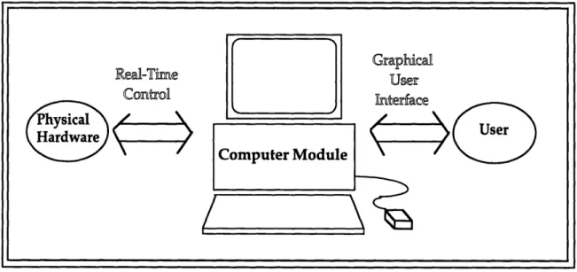
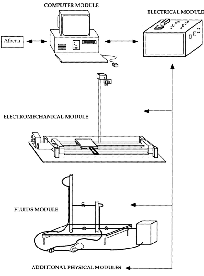
Overall Picture
Figure 3 shows the overall physical set-up design. It is primarily consisted of a Computer Module, an Electrical Module, and one or more Physical Modules. Figure 4 shows the schematic of the connections between
these components.
Modular Design Approach
The modular design concept is geared towards the open architecture objective, which allows the laboratory to grow with time and to be less susceptible to becoming obsolete. The way to achieve this goal is to make each one of the modules flexible and compatible with other modules. For instance, the software can be easily developed to suit the needs of each physical plant, the electrical module can be modified to meet the specifications of new actuators or sensors, and the physical module can be replaced, provided that the modifications follow a set of simple guidelines.
The main advantage to this design approach is that it enables graceful modernization of software and hardware components as upgrades become
available. Furthermore, it allows the adaptation of more sophisticated
physical systems, or the addition of physical modules from other mechanical engineering disciplines.
COMPUTER MODULE ELECTRICAL MODULE ~N c? ELECTRO]
C
FLUIDS MODULEADDITIONAL PHYSICAL MODULES 4
c
K
Figure 3. Overall Physical Set-up Design
4
t---
I
R--~--AthenaFigure 4. Schematics of Physical Set-up -Student Interaction
One of the intellectual requirements states that the students should have exposure to implementing the controls theory to more that one type of physical system. Therefore in the prototype set-up, two physical modules, a linear slide table and water tank level, which represent the electromechanical and fluid fields of mechanical engineering, have been included.
The following sections will present a more detailed descriptions of the three components that comprise the physical set-up.
Computer Module
Hardware
The heart of the laboratory station is a Dell 466 DX/2 personal computer, operating at 66 MHz with a 80486 processor and five 16 bit ISA expansion slots, a math co-processor, a 17" color monitor, 20MB of RAM and 210MB of hard disk. The clock speed of 66 MHz is selected because of the computational speed needed for performing real-time control algorithms. The math co-processor is necessary for the same reason. The ample RAM capacity is necessary to avoid "crashes" due to the number of applications running at the same time during the operation. A 17" monitor was chosen since the computer has to be viewed by two group members at the same time. Inside the personal computer is a DATEL PC412A multifunction I/O board, which provides 16 single-ended or 8 differential analog input channels capable of 83.3kHz of sampling rate and 12 bit A/D resolution. In addition, the board has 4 analog output channels and 8 input, 8 output discrete digital I/O channels. In addition, a U.S. Digital PC7166 encoder interface board consisting of 4 encoder counters, is installed in one of the ISA slot in the PC. A Video Blaster SE100 video board from Creative Labs is included in the PC to enable the incorporation of a vision system. For better graphics capability, a Diamond Multimedia Window's accelerator (SpeedStar Pro) with 1MB of video RAM is connected to one of the ISA slot. Last but not least, an ethernet board will be installed in the PC for future connection to Athena. These 5
daughter boards occupies all the ISA slots offered by the host computer. Software
The software interface between the various daughter boards and the computer is done through C programs developed in-house. These programs are documented in greater detail in Chapter 5.
In addition to the programs developed in-house, the personal computer is loaded with MATLAB version 4.2c as it's primary software. Mathworks' Simulink and Control System Toolbox are also part of the software libraries which enable students to carry out system dynamics simulation, see an animation of the response, and control system analysis. Moreover, performing real-time control of physical systems directly from MATLAB is done by linking it with in-house developed C programs (refer to
Notebook Suite and Microsoft Word (refer to Chapter 6 and [Tesciuba, 1995]). Furthermore, Mosaic is used as the World Wide Web browser for the students to view the laboratory handouts and on-line help [Hintersteiner,
1995].
This assortment of software shall provide the students a full perspective of control system design from system analysis to simulation, and ultimately a physical implementation of controllers and experimental data analysis. Furthermore, these tasks will be carried out without exiting the
environment of MATLAB. Under such a working environment, the
students will spend less time learning complicated commands, and thus will be able to focus their attention on the intellectual requirements of the course.
Refer to Appendix E for the cost breakdown of the Computer Module.
Electrical Module
The function of the electrical module is to serve as the interface between the computer and the physical modules. It provides the system with the necessary power to drive the actuators and sensors, the safety features to interrupt the system's process in an emergency, and additional features for incorporating extra analog circuits, such as lead-lag compensators.
Two power sources are included in the electrical module: one for the actuators in the physical modules, one for the sensors and peripheral components. The power source for the actuators consists of a power supply and two pulse-width modulated servo amplifiers (one for the electromechanical system and one for the fluid system). A filter card is connected to an amplifier to provide additional load inductance. The power source for the sensors and peripheral components are provided by single power supply unit, which gives out +12V, -12V, +5V, and common. Both power supplies need to be connected to 120V AC at 60 Hz and are housed in a chassis purchased commercially with in-house modifications.
The electrical module is designed such that extra analog circuits can be easily incorporated to the whole system. An array of standard electrical connectors located on the top of the chassis allow students to introduce analog circuits between the D/A output channels from the computer module and the servo amplifiers in the electrical module. Lead-lag compensation can be incorporated by plugging in circuits boards with lead-lag operational amplifiers circuits to these sets of connectors. The power for the operational
amplifiers are supplied by the +/-12 volt power sources inside the Electrical Module.
For safety, an emergency shut-off button is located on the top of the electrical module. In case of an emergency, the users can hit this button and the power to the actuators in the physical module is cut off immediately.
Connections to the multifunction I/O board in the computer module are done via a multi-colored flat ribbon cable with 25-pin male-female D-sub connectors, and a multi-colored flat ribbon cable with 9-pin male-female D-sub connectors for the A/D and D/A respectively. Four flat ribbon cables with 10 pin connectors are used to connect the electrical module with the encoder board in the computer module. All connectors on this end of the Electrical Module are protected from the students by a Plexiglas cover. The electrical
module provides seven connectors to the physical modules - one 9-pin
connector for the actuator signal, four 10-pin connectors for encoder signals, one 10-pin connector for the sensor signal, and one 4-pin connector for the sensor and peripheral power source. All connectors on this side of the electrical module offer strain-relief, can tolerate high voltages and high currents, and are single direction oriented for fool-proof purposes.
For detail design descriptions, specifications, and a cost breakdown of the electrical module, refer to [Tesciuba, 1995].
Physical Modules
With the current overall system design, each laboratory station can support a variety of physical modules, namely thermal, fluid, electromechanical, heat transfer, etc. Two versions of physical modules are developed as prototypes: a fluid module and an electromechanical module. Fluid Module
The fluid module is a water level control system. Two water tanks, one higher than the other, can be connected in coupled, uncoupled, and single configurations. The objective is to control the water level of the lower water tank.
During the project, two physical set-ups for the fluid module were developed. The first set-up was built to investigate the feasibility of the design. It includes two water tanks, a reservoir, a 12 Volt DC centrifugal pump, a pressure sensor, a 3-way ball valve, two needle valves, and the necessary connecting flexible tubing. All the tubes are made of clear plastic
materials to allow easy recognition of the water level by the students. As part of the fluid module, a simple analog circuit providing a sensor signal amplification gain of 100 is included to match the sensor's output voltage to
the input voltage level of the A/D card. The details of the design,
specifications, and results generated from this first generation fluid system set-up are documented in [Tesciuba, 1995].
The second generation fluid system refines the details of and made appropriate modifications from the original fluid system design. For detailed documentation of the second generation fluid system, refer to [Tesciuba, 1995] and G. Soto's bachelor's thesis [Soto, 1995].
Both set-ups for the fluid module were fabricated rather than purchased because similar systems were not commercially available for sale. In addition, no appropriate fluid system was revealed by our literature search (see Bibliography).
Electromechanical Module
The electromechanical module is a linear slide table driven by a servo motor. The control objectives here are the linear position and velocity of the sliding table.
In addition to the linear slide table, a number of accessories are included in the electromechanical module. A CCD camera is mounted onto this module as part of a vision system. Moreover, plant parameters can be adjusted by an inertial module which increases the rotational inertia of the system, and a friction module which applies extra friction to the plant. The additions of these accessories enable this physical system to illustrate more intellectual concepts to the students.
Detail design descriptions of this module are documented in Chapter 4.
Software Design and Selection
A combination of commercially available programs and programs
developed in-house is used in the new laboratory. The selection of
commercial software enables the students to use state-of-the-art programs to conduct simulations, view animations, perform analyses, etc., while the programs developed in-house allow for specific tailoring to suit the specific needs of the laboratory. Another reason for writing programs in-house was the lack of driver software available commercially for running real-time control with the hardware of choice.

![Figure 11 shows a photograph of the CCD camera and the camera mount. Refer to the [Laboratory Manual] for camera specifications and camera stand design drawings.](https://thumb-eu.123doks.com/thumbv2/123doknet/14678803.558710/50.918.140.720.583.979/figure-photograph-camera-camera-laboratory-manual-specifications-drawings.webp)