Design and Control of Supernumerary Robotic
Limbs for Near-Ground Work
by
Daniel Kurek
Submitted to the Department of Mechanical Engineering
in partial fulfillment of the requirements for the degree of
Master of Science in Mechanical Engineering
at the
MASSACHUSETTS INSTITUTE OF TECHNOLOGY
June 2017
@
Massachusetts Institute of Technology 2017. All rights reserved.
A uthor ...
Certified by ...
Accepted by ...
TE
Signature redacted
Department of Mechanical Engineering
May 12, 2017
Signature redacted
AvI. Harry Asada
Ford Professor of Mechanical Engineering
Thesis Supervisor
Signature redacted
...
t
Rohan Aberayatne
Chairman, Committee on Graduate Students
Design and Control of Supernumerary Robotic Limbs for
Near-Ground Work
by
Daniel Kurek
Submitted to the Department of Mechanical Engineering on May 12, 2017, in partial fulfillment of the
requirements for the degree of
Master of Science in Mechanical Engineering
Abstract
Supernumerary Robotic Limbs (SRLs) are a recent form of robot that augment natu-ral human abilities through the addition of body-mounted robotic appendages which can move independently of the wearer. This thesis provides a detailed analysis of the MantisBot, an SRL morphology that provides a wearer with two torso-mounted limbs that support the body in crawling- and kneeling-like positions, such that the wearer's natural arms are free to do useful work near the ground. First, the concept and its motivations are discussed, followed by a biomechanical analysis of the human-robot system. Two full-scale prototypes are then introduced, and control laws used in supporting a wearer's body both statically using impedance control, and dynamically using predictive models of natural crawling gaits, are developed. Finally, the system is experimentally validated, and it is concluded that SRLs for near-ground work are a valid and useful tool for improving worker comfort and productivity.
Thesis Supervisor: H. Harry Asada
Acknowledgments
First, thank you to my parents, Gaby and Jorge, and my sisters Sandra and Laura. My successes in life begin with your love and encouragement.
I would like to thank Professor Asada for his support throughout my career at MIT - your passion for innovation in research has been a powerful source of motiva-tion. In addition, thanks to all members of the d'Arbeloff Lab. The camaraderie and positivity through countless all nighters have made my experience in the d'Arbeloff Lab positive and unforgettable.
Finally, cheers to the Esteemed Squad and all the friends I've made during my time at MIT.
Contents
1 Introduction 15 1.1 M otivation . . . . 15 1.2 C oncept . . . . 17 2 Biomechanical Analysis 21 3 Prototype Design 25 3.1 First Prototype . . . . 25 3.2 Second Prototype . . . . 27 4 Control Design 35 4.1 Planar Quasistatic Impedance Control . . . . 354.1.1 Sagittal Plane . . . . 36
4.1.2 Frontal Plane . . . . 39
4.2 Data Driven Gait Characterization for Implicit Control in Robot-Assisted C raw ling . . . . 42
5 Experimental Validation 45 5.1 Planar Impedance Control . . . . 45
5.1.1 Procedure . . . . 45
5.1.2 R esults . . . . 46
5.2 Predictive Gait Modeling using PLSR . . . . 48
5.2.1 Discrete Window PLSR . . . . 49
6 Conclusion and Future Work 57 A Extended Results from PLSR Analysis of Human Crawling 59
List of Figures
1-1 Ergonomically challenging tasks near the ground. In (a) a contruction worker uses a passive dolly to support him as he cuts through concrete. In (b), a farmer bends down into an uncomfortable posture. A welder leans over a workpiece near the ground in (c). . . . . 16 1-2 MantisBot design concept using Supernumerary Robotic Limbs (SRLs).
Robotic limbs extending from the upper torso allow the wearer to as-sume more comfortable positions near the ground and actively provide tuneable impedance in multiple directions. . . . . 18 2-1 Sagittal plant projection of hybrid human-robot system . . . . 22 2-2 Maximum supported range of forward leaning for given actuator torques,
expressed in angular deviation of the SRLs and assuming a maximum range of 100 N of shear applied at the knees . . . . 23 2-3 Range of forces and torques borne by robotic limb over 30 cm of
head displacement. Above, ground shear refers to the component of the ground reaction force parallel to the ground . . . . 24
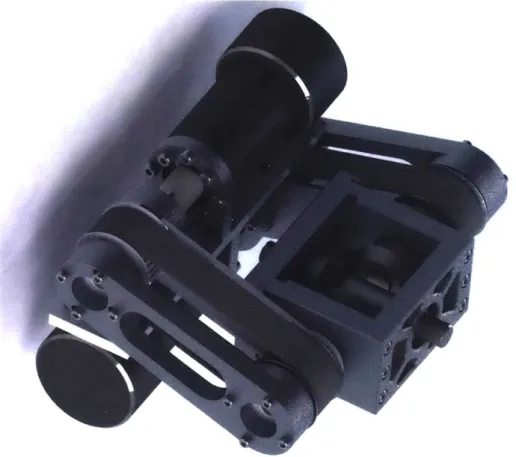
3-1 Prototype of the MantisBot used to test impedance control law. . . . 26
3-2 (a) Body-fixed axes used to describe actuator motion. The person modeled faces the reader. (b) A structural ball joint relieves the motor of radial stress. . . . . 27 3-3 Second prototype in operation with static legs . . . . 28 3-4 Rendering of 2-input bevel gear differential used in second MantisBot
3-5 Simplified representation of differential kinematics . . . . 30
3-6 MantisBot v2 in a retracted position . . . . 31
3-7 Rendering of actuated clamp mechanism used to lock SRLs (design and figure courtesy of Laura Treers) . . . . 32
3-8 Front view of MantisBot v2 . . . . 32
3-9 Back view of MantisBot v2 . . . . 33
3-10 Closeup of differential mechanism used in MantisBot v2 . . . . 34
4-1 Projection of human-robot system onto the sagittal plane. . . . . 36
4-2 The human body may be removed from the problem and replaced by the desired task-space forces. . . . . 37
4-3 Projection of human-robot system onto the xz plane. . . . . 39
4-4 Proposed system architecture for implicit controller used in and as-sisted crawling mode of operation . . . . 43
5-1 Impedance controller performance in the sagittal plane. . . . . 46
5-2 Impedance controller performance in the frontal plane. . . . . 47
5-3 Array of IMUs used to gather data for gait characterization and modeling 49 5-4 Average motion profile of ten manually identified single-cycle wrist tra-jectories compared to an exact minimum-square-jerk trajectory of the sam e tim e-scale . . . . 50
5-5 Normalized longitudinal wrist and knee acceleration profiles overlaid with minimum-jerk trajectories at moments of peak correlation, using a 20 Hz sampling rate . . . . 50
5-6 Gait discretization based on cross-correlation with minimum-jerk ac-celeration trajectory . . . . 51
5-7 Predicted vs actual arm trajectories using discrete window PLSR model 52 5-8 Predicted vs actual acceleration of left wrist during rolling window PLSR for forward crawling . . . . 54
5-9 Cumulative variance explained in output training data Y by latent variables in input training space, using 3 second rolling window . . . 55
A-1 Predicted vs actual acceleration of left wrist during rolling window PLSR validation for backward crawling, sampled at 20 Hz . . . . 59 A-2 Cumulative variance explained in backward crawling output training
data Y by latent variables in input training space, using 4 second rolling w indow . . . . 60 A-3 Predicted vs actual acceleration of left wrist during rolling window
PLSR validation for right translation, sampled at 20 Hz . . . . 61 A-4 Cumulative variance explained in right translation crawling output
training data Y by latent variables in input training space, using 4 second rolling window . . . . 61
List of Tables
5.1 Results of Impedance Control Tests . . . . 47
5.2 Forward crawling rolling window PLSR results . . . . 54
A.1 Backward crawling rolling window PLSR results . . . . 60
Chapter 1
Introduction
1.1
Motivation
Manual tasks in manufacturing and industrial settings often require workers to assume uncomfortable and fatiguing positions near the ground. When performing these tasks, workers must kneel or crouch in potentially painful postures, sometimes using their arms to stabilize and support themselves. Taking such an ergonomically challenging posture for long periods of time may lead to injuries in the lower back, knees, and ankles.
In one example, a worker may use a roller or brush to apply paint to a new ground surface. In such a task, the worker must sharply bend at the knee and back to reach the ground and balance, or lean forward in a crawling position and support himself with a free hand. In both cases, the painter's workspace is limited by the need to balance and support himself, and sustaining either position can quickly become tiring. This situation extends to a multitude of industries, including construction, manufacturing, and agriculture.
According to the US Bureau of Labor Statistics, in 2014 there were over 190,000 workplace injuries in manufacturing sectors and 50,000 injuries in agriculture
[6].
Overall, the cost of workplace injury amounted to over $190 billion and resulted in over 1.1 million lost days of work [4]. Out of all workplace injuries in 2014, approximately one in three was a musculoskeletal disorder [7].K.
(a) (b) (c)
Figure 1-1: Ergonomically challenging tasks near the ground. In (a) a contruction worker uses a passive dolly to support him as he cuts through concrete. In (b), a farmer bends down into an uncomfortable posture. A welder leans over a workpiece near the ground in (c).
Human augmentation via robotic systems provides a rich opportunity to address these issues. Exoskeletons have been applied to support factory workers in carrying heavy objects, assist nursing home caregivers in holding patients, and empower rescue workers wearing heavy protection gear [10][2]. These exoskeletons, however, move in parallel with the wearer's own limbs, and thus require the wearer to engage in all tasks the robot assists in. Exoskeletons may succesfully brace the human body, but they may also lock the wearer into specific configurations.
Supernumerary Robotic Limbs (SRLs) are a different type of wearable robot that provide the wearer with extra limbs. Whereas exoskeletons are directly attached to human limbs and move with them in parallel, SRLs branch out from the human body and take an arbitrary posture that is most effective for supporting the wearer. SRLs have the potential to be an especially effective solution for bracing the body of a worker taking fatiguing postures such as crawling, stooping, kneeling, and crouching. Perhaps most notably, they can provide this support while leaving the wearer's natural limbs free to do useful work and, given the additional support, comfortably and stably apply larger forces and torques than otherwise.
In the last several years various types of SRLs have been developed. These include a pair of robotic arms attached around the waist for assisting aircraft assembly workers
when using heavy tools [8], extra fingers for assisting hemiplegic patients in performing daily chores [9], and robotic arms sitting on the shoulder of a worker performing an overhead task [5]. In all of these designs, SRLs provided the wearer with unique physical supports, opening up new avenues of human augmentation.
In the current work, we aim to develop the MantisBot -a new SRL system designed specifically to support the wearer's upper body when performing fatiguing tasks near the ground. First, the basic design concept of the MantisBot is presented. Then control algorithms for supporting the body with a desired impedance are obtained, and a proof-of-concept prototype is designed and built. Finally experimental results support the control design and effectiveness of the wearable robot.
1.2
Concept
To improve the ergonomics of ubiquitous ground-space tasks, passive supports may be used to bear much of a worker's weight when working, as shown in Fig. 1-la. The additional support alleviates some of the stress that would otherwise be applied to the worker's joints, however such passive supports may still limit the user's range of motion and offer little to no compliance if the worker wants to change his body geometry.
By replacing passive supports with controllable actuators, the support provided can be tuned to exactly meet the needs of the task at hand, alleviating joint stress and fatigue, improving workspace, and increasing overall worker productivity. To this end, the MantisBot is introduced, modeled in Fig. 1-2. The MantisBot is a wearable robot that uses a pair of SRLs to actively and adaptively support its wearer. The device is worn around the upper torso via a rigid plastic harness from which the two SRLs extend and reach the ground when the user crouches or assumes a crawling position. Each robotic limb has 2 active rotational degrees-of-freedom (DOFs) at its shoulder and a passive linear DOF supported by an internal spring, though future iterations may include an active articulated elbow joint of prismatic joint.
ap-Figure 1-2: MantisBot design concept using Supernumerary Robotic Limbs (SRLs). Robotic limbs extending from the upper torso allow the wearer to assume more com-fortable positions near the ground and actively provide tuneable impedance in mul-tiple directions.
ply a virtual mechanical impedance on the wearer. As the wearer moves away from an arbitrary equilibrium position, the MantisBot provides a restoring force back towards the chosen central posture. By modifying the robot's control law, the relationship between restoring force and displacement can be tuned to exactly meet the needs of any activity. Such an impedance controller, which is common among robots meant to interact with humans, may also produce restoring forces based on the wearer's velocity within the current workspace, thus simulating a spring-damper (which may exhibit linear or nonlinear characteristics).
Revisiting the case of the painter, the MantisBot could provide support that al-lows for long and efficient longitudinal brushstrokes while maintaining balance and applying high stiffness and damping latitudinally. Overall, the painter could enjoy a more comfortable, extended body posture and improved productivity.
Each leg itself is comprised of telescoping segments that house the internal springs. As forces parallel to the limb axis vary, the limb shortens and extends. This allows the wearer to control the limb length - and, subsequently, global position - by changing the weight applied to the SRLs in addition to changing the SRL angles.
In Chapter 2 of this thesis, a biomechanical analysis of the proposed robotic sys-tem is presented in order to find the expected stresses applied to the human body and SRLs when the MantisBot is employed. Chapter 3 extends this analysis to the SRLs themselves in order to guide the design of two proof-of-concept prototypes used in quantitative experiments and qualitative field tests. Chapter 4 provides de-tailed derivations of feedback control laws developed to provide the robot with linear position- and velocity-based virtual impedance, and Chapter 5 validates the mechan-ical and control designs with the results of laboratory experiments.
In designs that include a third DOF along the length of the SRL such that it can be actively raised and lowered off of the ground, the MantisBot's abilities may possibly be extended to assist and dynamic motion and crawling-like motion, allowing wearers to move to new global positions without the use of their natural arms. In order for the robot to act appropriately in such situations without requiring explicit input from the wearer, the robot must be able to accurately predict the wearer's intention from available sensor input. To this end, Chapter 4 further details the use of Partial Least Squares Regression in order to form data-driven relationships between different parts of the body during natural crawling using Inertial Measurement Units (IMUs).
Chapter 2
Biomechanical Analysis
In this section a brief static biomechanical analysis of the hybrid human-robot system is presented. Through this analysis the robot's range of motion for given actuator effort limits are derived, and the corresponding forces and moments applied to the human within those limits are found.
To start, we first assume that the limiting cases with respect to both the loads transmitted to the wearer and the range of motion supported for a given range of actuator effort occurs in the sagittal plane, as shown win Fig. 2-1. This assumption may be justified with respect to the transmitted loads by referring to the prototype designs found in Chapter 3, as the majority of the forces transmitted across the frontal plane are borne by the compression of the base of the robot and harness, thus relieving the torso of potential strain.
We further limit the analysis by assuming that the robotic is massless (though the torso and upper leg are not). The system may therefore be modeled as a 4-bar linkage with a controllable torque at the robot shoulder, and with an additional shear force transmitted to the ground at the knee, produced by the human-controlled torque applied at the hip. Finally, the assumption is made that the MantisBot's pair of SRLs are collinear when projected onto the sagittal plane, and thus act as a single source of actuation with total torque output divided evenly between them.
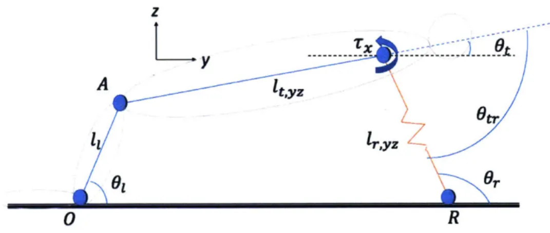
Given the location of the center of mass of the full system, as well as the locations of of the human knee and SRL endpoint (shown at points 0 and R in Fig. 2-1), the
z
A It'yz
6tr
61G
R
Figure 2-1: Sagittal plant projection of hybrid human-robot system
vertical reaction forces at the knees and endpoint are:
foz = fR,z mg(yR - YcoM) YR mg(ycoM) YR (2.1) (2.2) where m is the mass of the torso, g is the acceleration due to gravity, and ycoM is the y-coordinate of the center of mass.
Given a shear force at the knee fo,y, the torque produced at the hip is:
TA =
ItYZ
x o (2.3)and fA,z and fA,y are equal and opposite to fo,z and
fo,y.
Finally,Is
= -fATx = t,yz X fo - TA
(2.4)
(2.5) where the subscript S denotes forces at the SRL shoulder and t,y is the vector from the hip to the SRL shoulder. T2 is the total torque produced by both SRLs
together, and is the required torque to maintain the system at static equilibrium in
a given configuration.
Using average male body geometry and weight values from [1], we can plot the necessary ranges of SRL actuation required to maintain equilibrium as a function of the system's deviation from its central position, thus giving a means of designing the SRL for a desired range of motion.
The figures below assume a torso length of 0.533, upper leg length of 0.508, torso mass of 45 kg, a combined upper leg mass of 18 kg, and that the system's central position occurs at the point in which both the SRL and the upper leg are vertical. Further, the SRL shoulder is located axially along the torso at a distance of 0.3075 m from the hip.
Shoulder Torque Magnitude vs Robot Arm Angle
1 Arm 300 - 2 Arms 200- ~150-2100 -1 Range of actuator 0 -- 'torque required to
*50--2 maintain given angle
CO 0 - --- ---
--50 - Max stable range using 25 Nm actuators -100
-100 -90 -80 -70 -60 -50 -40 -30 -20
Arm Angle from Y-Axis (dog)
Figure 2-2: Maximum supported range of forward leaning for given actuator torques,
expressed in angular deviation of the SRLs and assuming a maximum range of 100
N of shear applied at the knees
Finally, this model also provides a mean of calculating the loads born by each SRL over a desired range of motion, which is useful in the design of the two full-scale prototypes discussed in the following chapter.
0.7 0.6 0.5 0.4 0.3 0.2 0.1 0
0.7 meter leg length
Famb shier Fombmp 30 -0.2 0 0.2 0.4 0.6 0.8 Arm ser 40 35 30 25 20 15 10 5 Ground Shear 30 E18 z 6 -18 CO, -0.3 -0.18 -0.06 0.06 0.18 Head Dispacement (m) 3 E e6 I-E -i a I8 0.3 -0.18 -0.06 0.06 0.18 0.3 Head Displacemsnt (m)
Figure 2-3: Range of forces and torques borne by robotic limb over 30 cm of head displacement. Above, ground shear refers to the component of the ground reaction force parallel to the ground
I
300 200 100 Sz 0 -100 -200 9w0 900 850 750 700Chapter 3
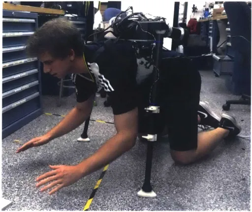
Prototype Design
To explore a practical implementation of the MantisBot concept, two full-scale pro-totypes were designed and fabricated. The first proof-of-concept prototype (shown in Fig. 3-1) uses pairs of gimbaled motors at each robotic shoulder two produce the necessary degrees of freedom to actuate the robot. The second builds on this design with a more robust, and stronger, differential configuration that uses the same motors to double output torque in principe directions.
3.1
First Prototype
For the first prototype, the torso harness was made using formable thermoplastic molded with a 3-D printed shell designed to approximate the shape of an average
adult male's chest. The inside surface of the harness is padded with high-density
memory foam to improve comfort and body-shape conformity. It extends roughly
3/4 of the way down the ribcage and its rigidity ensures that the torques applied
on the wearer by the robot do not strain the upper spine, which could result in uncomfortable spinal hyperextension or hyperflexion.
An aluminum plate is bolted across the back of the harness to form a base plate upon which the robotic hardware is mounted. Adjustable nylon straps worn over the tops of the wearer's shoulders connect the front of the harness to the aluminum plate. The front of the harness is split longitudinally, so that the wearable robot can be put
Figure 3-1: Prototype of the MantisBot used to test impedance control law.
on and removed like a jacket.
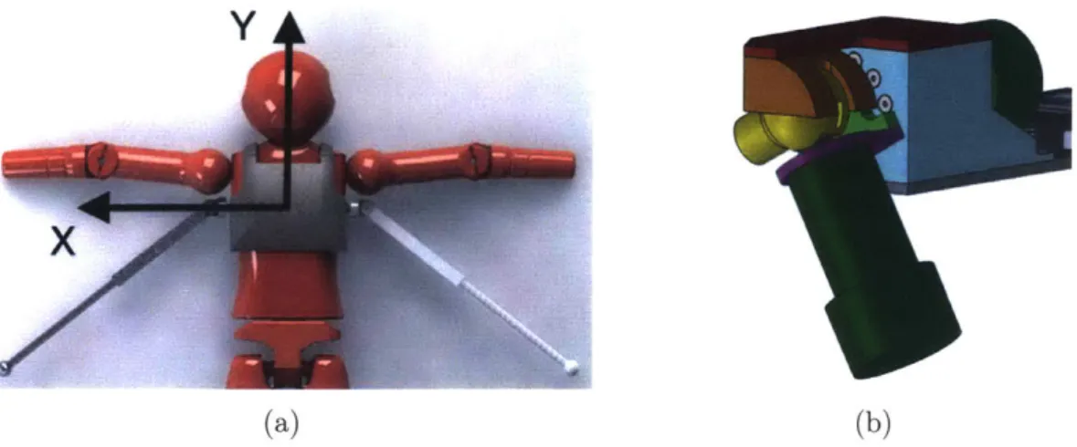
In the coordinate system shown in Fig. 3-2a, both primary shoulder motors are rigidly attached to the back of the torso harness with their shafts aligned with the x-axis. These shafts are connected to the housing of their corresponding secondary shoulder motors such that the entire secondary motor rotates about the x-axis, within the sagittal plane. The motors are positioned so their shaft axes are co-planar and orthogonal, simplifying control of these two rotational DOFs. The limb itself then extends out from the secondary motor orthogonally relative to the output shaft.
The 2 DOF shoulder joint is supported by a ball-and-socket joint housing, shown in figure 3-2b, so that any forces transmitted axially through the limb are borne by a structural socket also attached to the harness, relieving the motor shafts of any damaging radial strain.
All 4 shoulder motors are Maxon EC60 Flat 3-phase AC motors reduced by a ratio of 81:1 via Maxon GP52C planetary gearheads, and driven by ESCON 50/5 motor controllers. At the output, the actuators can produce up to approximately 30 Nm.
Y
x
(a) (b)
Figure 3-2: (a) Body-fixed axes used to describe actuator motion. The person mod-eled faces the reader. (b) A structural ball joint relieves the motor of radial stress.
The length of the SRLs are telescoping carbon fiber tubes with internal springs that provide an effective spring constant of 3236 N/m, and allow a travel of 10 cm, giving the limbs' lengths an overall range of 0.72 - 0.82 m. Sharp GP2YOA41SK0F infrared proximity sensors are used to measure limb lengths and provide information on the compressive axial forces applied to the limbs. The bottoms of the SRLs are capped with wide 3-D printed pads lined with high-density rubber, providing ample traction with the laboratory floor.
UM7 9-DOF Inertial Measurement Units (IMUs) mounted on each SRL provide roll and pitch information to a PC running Windows 10 via Bluetooth. An onboard Arduino Due 32-bit microcontroller aggregates all encoder and proximity sensor data and interfaces with the ESCON motor controllers.
Python scripts on the PC use the C-based Numpy linear algebra library to calcu-late control efforts based on incoming data and send commands back to the onboard Arduino.
3.2
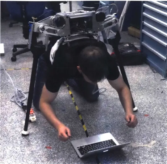
Second Prototype
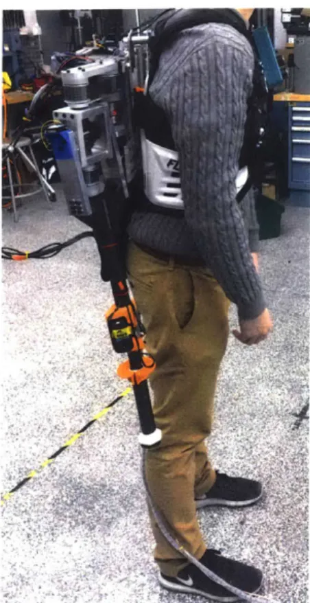
The second prototype improves upon the first by replacing the molded thermoplastic harness with a modified motocross chest protector which provides better support and more breathable padding across the chest and shoulders. Aluminum plates were
Figure 3-3: Second prototype in operation with static legs
attached to the back of the harness for added rigidity and to provide a surface to which the SRLs and electronics could be added.
After finding through experimentation that the shoulder actuators could benefit from increased torque output, the robotic shoulders were redesigned to work in a 2-input bevel gear differential configuration, shown in Fig. 3-4. When both motors rotate in the same direction, the differential unit rotates about the axis shared by the input bevel gear shafts. When the motors are driven in opposite directions, the output shaft upon which the middle bevel gear sits rotates about its own axis. Linear combinations of these input modes can be used to produce torque about any axis that then lies within the plane spanned by the bevel gears' axes. In this design, the motors are offset using belt drives to save space and to easily vary the drivetrain reduction as necessary. Further, such a design provides an increased range of motion, which allows
for a fully retracted limb position that does not interfere with the wearer's workspace when the robot is not in use, as shown in Fig. 3-6.
Figure 3-4: Rendering of 2-input bevel gear differential used in second MantisBot prototype
To derive this relationship, we refer to Fig. 3-5. Assuming the right and left input shaft angles are given by Oi, and 0
i,2, the ouput angles are 0,,1 and 0,,2, and all bevel
gears have equal pitch radii, then:
00,1 = Oi,2 - 1 (3.1)
00,2 i,2 + Oi
2 -(3.2)
We may then differentiate these equations and invert the resulting Jacobian matrix to derive the bevel gear's input-output relationship.
Figure 3-5: Simplified representation of differential kinematics d60 [-0.5 0.5 (3.3) d6i 0.5 0.5 =i ut (3.4) --11 Tin = rout (3.5)
Thus, assuming each motor can output a maximum torque of Tmax, the bevel gear
can produce a maximum output torque of 2Tma, about either output axis. Intuitively the shoulder motors act to drive the output shaft in parallel, and thus their torques
are additive.
The first prototype's Maxon EC60 Flat 3-phase AC motors and corresponding gearheads and drivers were reused in the second prototype, though the infrared re-flectance proximity sensors used to measure leg length and spring compression were replaced with STMicroelectronics VL53LOX time-of-flight sensors for improved noise characteristics and signal linearity. UM7 IMUs with embedded Kalman filters were again used to determine state estimates of each limb's orientation and position in space.
For added adjustability, an additional telescoping stage was added along the length of each limb, along with actuated clamps to lock them in place with the press of a button located near the tip of the SRL. When locked, a Dynamixel MX-106 drives the worm gear of a hose clamp mounted around the inner carbon fiber tube of the
Figure 3-6: MantisBot v2 in a retracted position
telescoping limb, thus preventing relative motion between the tubes under axial loads. Overall, the majority of components on the second prototype were water-jetted or machined aluminum and steel, resulting in a much more mechanically robust, and much heavier, final product compared to the first prototype, which used many 3D printed components. Whereas the first prototype weighs 8.2 kg, the second weighs
Figure 3-7: Rendering of actuated clamp mechanism used to figure courtesy of Laura Treers)
Ll
U
lock SRLs (design and
f~'t
Chapter 4
Control Design
4.1
Planar Quasistatic Impedance Control
In this section we aim to derive control laws for supporting the wearer with a desired impedance. In [8] a feedback control algorithm for supporting the wearer is reported for a general 6 DOF SRL system with 6 independent actuators. In the MantisBot, two of the actuators are replaced by passive springs. While this underactuation simplifies the physical design, it also limits the achievable impedance. The following analysis will reveal the range of this achievable impedance, and synthesize a control law that realizes a desired impedance within that range. Further, in the analysis and synthesis below, the 6-dimensional space is divided into two 3-dimensional spaces: one within the sagittal plane and the other in the frontal plane, simplifying this initial exploration of the MantisBot's use cases. We assume motion is limited to within only of these planes. Thus the system is symmetric and no principal axis of stiffness spans both the sagittal and frontal planes, justifying this simplification.
Though gravitational forces are not explicitly handled in the derivations, length measurements of the SRLs' internal springs serve as indirect measurements of gravity's influence on the system.
4.1.1
Sagittal Plane
First we examine the human-robot system projected onto the body-centered sagittal-plane. As shown in Fig. 4-1, we assume that the robot's two SRLs are aligned. Therefore when operating in this plane, the two primary shoulder motors act as a single actuator producing one active DOF. The chosen goal, then, is to derive a control law that defines a virtual impedance along the y-axis.
Both the knee-ground contact at point 0 and the robot-ground contact at point
R are rotationally free pin joints that do not slip along the ground.
z
y
A Oy
0 R
Figure 4-1: Projection of human-robot system onto the sagittal plane.
The influence of the robotic limb on the wearer's torso may be abstracted as a pair of orthogonal translational forces F. and Fz, and a moment Me equal and opposite to Tx. We can therefore remove the human body from the problem entirely and focus
exclusively on producing the desired forces, as shown in Fig. 4-2. As the length of the leg acts as a rigid body in rotation, and considering only static balance, T, may be moved to point R without loss of generality.
We must note that a necessary and sufficient condition for static balancing and support is that the human applies forces and moments back onto the robot that are equal and opposite to those produced by the robot itself. We therefore assume that the human is able to adapt to meet this condition and maintain static equilibrium.
Fzt
lr,yz
r
Figure 4-2: The human body may be removed from the problem and replaced by the desired task-space forces.
Tx = TX(Or, ilr,yz; Or,O, lr,yz,O, ) (4.1)
for some arbitrary equilibrium joint-space position (9
r,O, ir,yz,O), such that the desired y-axis impedance is achieved. In this derivation, the goal impedance is equivalent to a tuneable spring-damper system:
Fy = ky,pAy + kv,dAy (4.2)
where:
AY = lr,yz,OCO0Sr,O - lr,yzCOSOr (4.3)
Ap = lr,yzsinOrkr - Cosorir,yz (4.4)
Our analysis begins by deriving a static relationship between joint-space and task-space forces via the Jacobian J. Starting with the forward kinematics:
Z = lryzsinOr
We differentiate with respect to joint-space coordinates and produce the following relationships. r = JT
F
F = [Fy, FZ]T (4.6) (4.7) J - r,yzsinOrL
1r,yzCOSOr COSOr sinOr , (4.8)Above, Fily corresponds to the passive force produced by the SRLs' internal springs, which act axially along the compound SRL created by projecting the aligned limbs onto the sagittal plane. We denote the effective spring constant created by the
parallel SRLs as kspring.
We then solve for T, as a function of the measured spring force F, and the desired impedance Fy.
TX = -1r,yzcscOrFy + lr,yzCOtOrF z (4.9)
Substituting in the force-length relationship F, = kspring Alspring where Alspring =
lr,yz,unsprung - ir,yz, and Eq. 4.2:
TX = - tr,yzCSC~r (kYIAy
+
ky,dAy)+ rI,yz COtOrkspring A1 spring
(4.10) (4.5)
y = 1r,yzCOS~r
Finally, substituting in Eqs. 4.3 and 4.4 we produce the final joint-space control law:
TX = - lr,yzCSC~r(ky,p(r,yz,0COS0r,0 - lr,yzCOS0r)
+ ky,d(lr,yzSinrjr - COSOrlr,yz)) (4.11)
+ lr,yzCOt~rkspring (lunsprung - lr,yz)
4.1.2
Frontal Plane
The system projected onto the frontal plane is shown in Fig. 4-3. Once again the human body is replaced with the forces and moment applied by the MantisBot (here at point B), Fx, Fz, and My. The two secondary shoulder motors comprise two controllable DOFs in this plane. The robot can therefore apply a virtual impedance on the wearer in two directions, chosen to be along the x-axis and rotation about the y-axis. z B x sryR
C
ot---T y,LA
B----
-_----_---_=:-::
---0 tr,R LOtr,L r,L :z rR * 0r,R Or,L G, D x
Figure 4-3: Projection of human-robot system onto the xz plane.
As before, the goal is to derive a set of joint-space control laws:
Ty,R Ty,R( q; qO) (4.13)
where:
q = [Or,Li ,r,Li Or,Ri ir,R -(.4
90= [r,L,O, 1r,L,O, Or,R,O, lr,R,O]T (4.15)
that satisfy the desired virtual impedances:
Fx = kx,pAx + kx,d/AiJ (4.16)
My = k4t,At + kot,dAt (4.17)
relative to some arbitrary equilibrium position, denoted by 0 subscripts.
Noting that the frontal plane projection is a closed kinematic loop, we begin with the inverse kinematics, calculating joint-space coordinates from task-space coordi-nates.
= taV1 2z - lssinkt\
Or,L = tan- 2z-1 io4.18)
2x - lcos(4 1r,L 2z -
lsinot
(4.19) 2 sinr,L(
t2z + lsint( 2xD - 2x - iscos( 1 rR= 2z + lsint (4.21) 2sinO,,RDifferentiating with respect to task-space coordinates x, z, and
#t
we derive the Jacobian J E 9zI . This satisfies the static relationship:r = [Tr,L, Fr,L, Tr,R, Fr,R]T
Rearranging the 4 linear equations represented in Eq. 4.22, we solve for Tr,L and
Tr,R from measured spring forces and the desired task-space impedance forces.
r * = J*T F* where J* . 914x2 (4.24)
r* = [TrL, Tr,R ]T F* = [F,, My, Fr,L, Fr,R ]T
We define the forces in F* in terms of displacements using the Laplace variable s:
F* = Kp*zAp* Alr,L Al r,R kx,p + kx,ds 0 0 xo - X OtO- q5t rLAunsprung - 1r,L ir,,Aunsprung - 1r,R 0 kt,, + k4,,ds 0 0 0 0 0 4n 0 (4.26) (4.27) (4.28)
[
0 0 0 kspringjand finally we relate the input coordinate vector Ap* to joint space coordinates using forward kinematic relationships such that Ap* = Ap*(q; qo).
AZX = XO - lr,LCOS(Or,L) - COS( t)
2 (4.29) and (4.25) Ap * F=[Fx, Fz, MY]T (4.23) 11 U k.
A = -t qt,o - t3
where
_=
tan- (r,,Rsin(r,R) - r,Lsin
(O,
) (4.31)1,r,RCOS(Or,R ) -1 re,LCOS(r,L ) + XD
Alternatively, the right-hand joint coordinates may also be used to calculate the end-point location.
Thus, the relationship:
= J*TK, _ Ap*(q; qo) (4.32)
achieves the desired task-space impedances while satisfying Eqs. 4.12 and 4.13.
4.2
Data Driven Gait Characterization for Implicit
Control in Robot-Assisted Crawling
Perhaps the most interesting potential mode of operation of the MantisBot and sim-ilar robots is that in which the robot dynamically assists the wearer in supporting, balancing, and possibly even propelling the wearer in large-scale motion, such as crawling along the floor to an entirely new position in the global workspace. To do this in such a way that maintains the benefits of allowing the wearer to remain phys-ically and mentally engaged with the task at hand, the concept of implicit control is introduced. It is proposed that rather than requiring the wearer to explicitly alert the robot to his or her desired intention (e.g. crawling forwards, rotating about a vertical axis, or stopping a crawling gait) through a hand-operated controller or voice control, the robot could instead monitor a suite of motion and force sensors located around the wearer's body and, via the use of data-driven predictive models of human mo-tion, automatically determine the wearer's intention and correct corresponding SRL trajectories.
A proposed control system architecture is shown in 4-4. In this system, previously produced predictive kinematic models derived from real crawling motion and force data is used in a Support Vector Machine (SVM) to categorize the wearer's current and short-term future intent into discrete categories of motion, such as forward or reverse crawling, lateral translation, or rotation about a vertical axis. In parallel, a continuous state-space predictive model derived using Partial least squares regression (PLSR) predicts the trajectory the wearer's natural arms would have taken in normal crawling. Based on the robot-human system's current state as estimated from a real time body observer, these predicted trajectories would then be transformed into SRL trajectories by determining specific endpoint positions that would produce equivalent reaction forces on the wearer's body.
Planner Drivers Body Observer PLSR Robot Predictor Sensors Kneepad . Sensors Predictor Data Driven Model
--- I
Figure 4-4: Proposed system architecture for implicit controller used in and assisted crawling mode of operation
Partial least squares regression is a statistical regression technique that, given n samples of a p dimensional input data vector and an m dimensional output vector, a linear relationship of the form:
Y = X,3 + 00 (4.33)
predicted output data, and # and /O are weighting and residual offset matrices. In PLSR, the matrix
#
minimizes the error between Y and X3 by finding the directions in X that explain the most variance in Y. Thus, PLSR produces up to n latent variables in the space spanned by X that can be used to further predict output data given new sets of input data. In datasets with highly structured covariance structures, it often takes just of a few of these latent variables to explain most of the variance in the output space. Latent variables that explain lesser amounts of variance in Y often end up regressing on noise in the system, and thus may possibly be left out of the resulting predictive model to avoid overfitting of data.Partial least square regression was used in proof-of-concept experiments performed to validate the foundation upon which the control architecture above is based, and the methodology and results of these experiments are given in the following chapter.
Chapter 5
Experimental Validation
5.1
Planar Impedance Control
5.1.1
Procedure
To test the efficacy of the MantisBot and the control laws derived above, the forces produced by the system were measured externally over a wide range of task-space coordinates. Optoforce OMD-45-FH-2000N 3-axis optical force sensors were fixed between the bottom of the SRLs and the ground such that the sensors' axes remained aligned with global coordinates. A subject then put on the MantisBot (version 1) and the robot was activated. The subject was asked to move slowly within a comfortable range in either the sagittal or frontal plane.
In static equilibrium the reaction forces detected between the ground and SRLs must be equal and opposite to those applied to the subject at each respective SRL shoulder. Thus the force sensors provide a measure with which the target impedance forces can be compared. Sagittal and frontal plane impedances were tested separately using various virtual spring constants.
In all trials, the equilibrium position was chosen so that the SRL angles were normal to the horizontal ground plane, and their equilibrium lengths were set at a position comfortable to the wearer. Data points in which the wearer deviated from the respective plane by more than 5 degrees were excluded from the results.
Experiments were conducted with Institutional Review Board approval from the Massachusetts Institute of Technology (Committee on the Use of Humans as Exper-imental Subject (COUHES) Case No. 1606621285).
5.1.2
Results
Shown in Figs. 5-1 and 5-2 are the resulting force profile for y-axis impedance in the sagittal plane, and x-axis impedance in the frontal plane, respectively. In both cases, the tested desired stiffnesses are 0 N/m and 400 N/m.
EupewknnWaI yxis Rsstorng Forn, Pro in SigiW Phimn
E
EpeInwiK~p a00 s KfO .0 yd |i0N-4
15 0 ExpkvuWnt0 Nn,K,d 0 N-ovn 10 0 -15 -003 -0.01 0 0.01 0.0 0. Y d~ispnt i Betal Pta* (in)
Figure 5-1: Impedance controller performance in the sagittal plane.
At 0 N/m, the actuators should work just enough to cancel out lateral reaction forces transmitted via the SRLs, so that the wearer feels no net force along the x-or y- directions. At 400 N/m, the fx-orce profiles should take on a negative, stable slope as the reaction forces increasingly push the wearer in the negative direction as displacement becomes more positive. As shown in the figures and in Table 5.1, the controller succeeds in tracking the desired force-displacement profiles quite well.
We note that due to actuator saturation, there is a finite range over which the robot can stably support its wearer. Error calculations performed to determine the controller's performance used data from within those ranges, which were
approxi-Expermenol x-eis Resioring Force Pmofs In Frantal Phne a Expedm m KP -400 N/n. Kd a 0 N-ahu --TNWWWFore Pon00 30 0 EPiWmU K 0 ~p N.K d 0 N-ti 0 - Theoeeeffi or e Prib 10 -10. 0.1 -0. -0.06 -GOM 0 0.02 0 0.06 00 0.1
X dsplacement in Frontal Plane (m)
Figure 5-2: Impedance controller performance in the frontal plane. Table 5.1: Results of Impedance Control Tests
Test RMS Error (N) Standard Deviation (N) Range Along Axis (in)
Sag. Plane, ky, = ON/m 3.7 7.9 [-0.04, 0]
Sag. Plane, ky, = 400N/m 0.9 7.5 [-0.04, 0.04] Fr. Plane, kxp = ON/m 3.2 14.3 [-0.05, 0.05] Fr. Plane, kxp = 400N/m 3.7 10.5 [-0.05, 0.05]
mated graphically. We also note that the controller's feasible range in the frontal plane is significantly larger than in the sagittal plane, which is attributed to the different geometries of each pose. In the frontal plane, the body's projected center of mass is suspended between the SRLs' ground contacts such that when moving from side to side, the moment applied by the center of mass on one of the SRLs de-creases over a few centimeters of motion. Further, the sagittal plane's feasible range exhibits clear asymmetry - as the wearer (and center of mass) moves from back to front, the fraction of body weight supported by the SRLs, rather than the wearer's knees, increases. Thus, the magnitude of the moment resisted by the SRLs is larger in forward-leaning positions.
Though the tested range of about 4-5 cm in the 400 N/m cases can be considered relatively small, this can be extended by using stronger actuators or decreasing the lengths of the SRLs. Further, it should be noted that while the actuators can only track the desired force profile accurately over this range, the system provides some
degree of support over a much larger range, reaching 8-10 in the 0 N/m cases. Finally, we attribute larger errors near zero displacement to a combination of IMU bias and backlash in the robot's drivetrain. Slight differences in measured and true positions near the chosen equilibrium point can cause the SRLs to work with gravity rather than against it over small ranges, and rapid changes from positive to negative torque in the presence of backlash can create large dynamic forces measured by the sensors used in the experiment.
5.2
Predictive Gait Modeling using PLSR
In order to validate the possibility of developing the predictive kinematic models needed in the proposed architecture, partial least squares regression (PLSR) was used with experimentally gathered Inertial Measurement Unit (IMU) data produced by live subjects performing crawling gaits. UM7 IMUs were placed on subjects' ankles, knees, chest, forehead, and wrists, and 3-axis acceleration angular velocity, and pitch/roll Euler angle data was recorded from each unit, resulting in a 64-D data vector produced at every sample. This vector was then split into a 48-D input vector containing ankle, knee, chest, and head data, and a 16-D output vector containing wrist data. These vectors were then temporally expanded by adjoining adjacent samples covering approximately 10-4000 ms of IMU data, therefore mapping potentially large periods of time to single points in extremely high-dimensional state spaces, and capturing large quantities of current and past information at every point in time. In one form of this analysis, a MATLAB program was used to identify individual gait cycles based on wrist acceleration and then temporally normalize and reparameterize all data in each individual cycle for further processing. In another form, the time-window of included samples remained fixed and rolled forward continuously, shifting data within the input vectors as it moved.
-Y Y
Wrists forward
Figure 5-3: Array of IMUs used to gather data for gait characterization and modeling
5.2.1
Discrete Window PLSR
[3]
makes the observation that point-to-point human reaching tasks exhibit minimum-squared-jerk acceleration profiles, which for a given period period T and position x, is given by:x(t) = XO + x10(t) -15
()
6(
(5.1)As can be seen in Fig. 5-4, this observation is, on average, also true for point-to-point wrist motion in crawling gaits, and thus provides a convenient means of auto-matically identifying and extracting individual crawling cycles from acceleration data. By normalizing the longitudinal knee and wrist accelerations relative to each trial's standard deviation and then cross-correlating the resulting signal with an appropri-ately scaled minimum-square-jerk acceleration profile, the middle of each cycle can be reliably captured when thresholding the resulting peaks in the correlation. Lift-off and touchdown points for each limb can then be identified with further thresholding
O 6086
M~4, 1 1@6 0 . OAS01 0.2 Oil 02 OiM 0.4 OAS 065
-
-1
04 0 *A 0 016 *A U &S 04 C 06 0 0 0 00 0 00 1 i 0.5 0.2"i6 i 0. 4 *A 03 40 0 OA 0.1 016 UiOlS i 0AS 0A 06 0.5 samplamFigure 5-4: Average motion profile of ten manually identified single-cycle wrist trajec-tories compared to an exact minimum-square-jerk trajectory of the same time-scale of the acceleration profiles.
Mind (A4 wn, frexapIn Le, Of Z -M )r
2 A
-
*2-0 60 100 160 200 2600 360 400 460 600
-Figure 5-5: Normalized longitudinal wr~~iadke ceeainpoie vradwt
TIU CIO
2
--221
ThOM (WOc
Figure 5-6: Gait discretization based on cross-correlation with minimum-jerk accel-eration trajectory
over its period and standard deviation, and then interpolated at 20 equally spaced points in the individual cycle trajectory. Thus, gait motion profiles exhibiting varying periods and magnitudes are recast to comparable dimensions assuming the trajectories scale linearly with these changes.
Upon performing PLSR on the resulting normalized and discretized gait cycles
- now represented as single points in a high-dimensional state space - it becomes clear that there is, in fact, a clear relationship between human arm motion during crawling and the corresponding motion of the rest of the sensed points on the body. The result shown in Fig. 5-7 was found after taking data from 10 cycles of forward human crawling at a comfortable speed, automatically parsing and normalizing all trajectories using cross-correlation with a minimum-jerk profile, and producing the predictive linear model with MATLAB's plsregress( function. Data from 4 more cycles were then parsed, and each input cycle, which includes data from everything apart from the wrists, was used with the predictive model to produce an expected arm trajectory which could be compared to the actual trajectory.
A clear limitation of this method for predicting arm motion during crawling is that it cannot be used in real time. Since the entire predicted gait cycle must occur before being parsed and fed into the PLSR model, the resulting prediction is no longer useful. However, extensions of this method could likely include a prediction of future
Hand Zmaccel Cross Validation
1
Prediction
Actual
0.5
Accel (g) 0-0.5
-10
5 samples10
15
20
Figure 5-7: Predicted vs actual arm trajectories using discrete window PLSR model
gait cycles based on trajectories of previous parsed cycles.
5.2.2
Rolling Window PLSR
An alternative approach to predicting gait motion is to use a rolling time window of data samples and continuously make predictions of instantaneous arm acceleration, velocity, and angular position in space. More specifically, defining a row vector of input data samples at time k as (tk), and a number of samples w to include in the
augmented input vector that covers a time window t., = wt, given a sampling rate of
1/t, Hz, the augmented input input vector is given by:
Xaugmented = [k k-1 -- k-w+1 Xk-w] (5.2)
laugmented,w Xw !w-i ... t01 :o
Xaugmented,w+1 Xw+1 Xw --- X2 X1
Xaugmented,w+2 Xw+2 Xw+1 --- 3 t2
X (5.3)
Xaugmented,n Xn Xn-1 --- Xn-w+1 Xn-w_
and the corresponding output matrix of instantaneous arm-sourced data is:
Vw+1
Vw+2
Y = .(5.4)
where q(t) is a row vector of wrist accelerations, angular velocities, and Euler angles.
PLSR was run on 1 minute of training data recorded at 50 Hz during trials where a single subject crawling across the floor forward, backward, and translating to the right. The data was then downsampled to 20 Hz to eliminate high frequency noise and decrease the computational load required to regress onto the PLS model. The data was then expanded as shown in eq. 5.3 using window sizes of 1, 5, 10, 20, 50, 60, and 80 samples, resulting in 7 separate potential prediction models per mode of crawling.
For validation, each of these predictors then predicted the resulting arm motion of an additional 5 seconds of crawling data using between 1 and 30 of the latent variables produced during the regressions.
set of plots shows the predicted vs actual normalized longitudinal (z) acceleration of the left wrist as a representative visualization of the full 16-d prediction trajectory, as well as the cumulative variance in output data captured by best regression's latent variables. The root-mean-square error values given in the additional tables were calculated by taking the average of the norm of the error between the prediction vectors and ground truth vectors, normalized with respect to the standard deviation of the ground truth data. Results for the backward and sideways crawling are similar to those shown below, and can be found in Appendix A.
SD
A Actual Left Hand Z Accel vs Predcted Left Hand Z Accel (Standardined)
3-2
0 N
.-50 80 70 soS0 pe 90 100 110 120
Figure 5-8: Predicted vs actual for forward crawling
acceleration of left wrist during rolling window PLSR
Table 5.2: Forward crawling rolling window PLSR results
Window Size (samples) Optimal number of latent variables Average RMS Error (Fraction of SD)
1 24 0.601 5 19 0.601 10 24 0.557 20 24 0.439 50 25 0.449 60 28 0.431 80 30 0.444
Qualitatively, as shown in Fig. 5-8, the PLSR predictor tracks the ground truth arm trajectory reasonably well. However, high frequency noise in the prediction tends
100 i Percent Variance Explained In Y 10 90 -~70 80 40 -30 20 101I 0 5 10 15 20 25 30 Number of PLS Components
Figure 5-9: Cumulative variance explained in output training data Y by latent vari-ables in input training space, using 3 second rolling window
to drive up the resulting root-mean-square error, which may be a result of the high number of latent variables needed to predict the trajectory (as shown in Fig. 5-9). As a preliminary conclusion, it appears from these experiments that using PLSR from gait prediction is a feasible option, though likely requires further development for practical use.
Chapter 6
Conclusion and Future Work
In this thesis, a novel robot morphology using Supernumerary Robotic Limbs (SRLs) was introduced and developed with the purpose of stably and comfortably supporting the human body when performing tasks near the ground. A potential need for such a device was established by examining work-related injury data and real-world issues faced by workers in various injuries, and the general structure of such a device, known as the MantisBot, was outlined. Then a brief biomechanical analysis of the MantisBot was performed, showing that the MantisBot could support the human over a useful range of motion while maintaining safe levels of force and torque application to the human body, and with readily available actuators. Control laws were derived for adjustable impedance control in a quasi-static mode of operation by decomposing spatial motion of the human body into the sagittal and frontal body planes, and an experimental validation of these control laws on full-scale prototypes was presented to prove their ability to apply adjustable and linear spring-like restoring forces onto the human torso. Finally, the possibility of using predictive, data-driven statistical models of human crawling gaits to drive the implicit control of the MantisBot during dynamic operation was found to be feasible.
The MantisBot -and SRLs in general -provide an exciting opportunity to discover new modes of human-robot interaction in a largely unexplored branch of robotics. Fu-ture iterations of the MantisBot can easily be designed to be lighter and stronger to further extend the range of motion through which a wearer may be stably supported,
and it is clear that the logical next step in the control design of the proposed sys-tem is full 6 degree-of-freedom impedance control and stabilization. Finally, deeper exploration of crawling gait characterization provides a rich breadth and depth of methods with which to effectively plan SRL trajectories during various modes of dy-namic motion along the ground, and may generalize to assist in the control of other
SRL morphologies.
Broadly, Supernumerary Robotic Limbs have the capacity to augment and assist humans in countless ways, and it is the conclusion of this thesis that their development as tools for industry will prove them to be indispensable in the future.
Appendix A
Extended Results from PLSR
Analysis of Human Crawling
2 1.5| 0.5 SD 0 -0.5 -1.5F -2 -2.5
Actual Left Hand Z Accel vs Predictsd Left Hand Z Accel (Standardized)
60 70 80 Samples 90
Figure A-1: Predicted vs actual acceleration of left wrist during rolling validation for backward crawling, sampled at 20 Hz
window PLSR -- Kd I I I I I 100 110 120
""I
I90 Percent Variance Explained In Y 701 60 501-30 20 10 1-0 0 5 10 16 20 Number of PLS Components Figure A-2: Cumulative variance explained in backward data Y by latent variables in input training space, using 4
Table A.1: Backward crawling rolling window
26 30
crawling output training second rolling window PLSR results
Window Size (samples) Optimal number of latent variables Average RMS error (Fraction of SD)
1 7 0.858 5 27 0.736 10 26 0.665 20 29 0.618 50 27 0.557 60 28 0.540 80 30 0.527
Table A.2: Right translating crawling Rolling Window PLSR Results Window Size (samples) Optimal number of latent variables Average RMS error (Fraction of SD)
1 26 0.725 5 24 0.642 10 30 0.589 20 27 0.560 50 30 0.522 60 30 0.553 80 30 0.490 8