FRESH GAS UTILIZATION OF EIGHT CIRCLE SYSTEMS
A. M. ZBINDEN, P. FEIGENWINTER AND M. HUTMACHER
SUMMARY
The fresh gas utilization (FGU) of a semi-closed breathing system is defined as the ratio of the amount of gas reaching the patient's lungs to the total amount of fresh gas flowing into the breathing system. It indicates to what extent a breathing system conserves anaesthetic gases and provides inspired gas concentrations as close as possible to those in the fresh gas, even at low fresh gas flows (FGF). We have measured FGU in eight circle systems used conventionally in Europe: Drager Cicero, Drager Sulla 808V with circle system 8 ISO and ventilator Ventilog, Drager AV1, Ohmeda Modulus II Plus, Gambro Engstrdm Elsa, Siemens Servo Ventilator 900 D with circle system 985, Siemens Ventilator 710 and Megamed 700A with circle system 219. The Tests were performed according to the Draft European Standard "Anaesthetic Workstations and Their Modules ". None of the systems tested showed the characteristics of an ideal system which would reach 100% FGU with an FGF less than minute volume. At FGF 3 litre min-', FGU was: Gambro Engstrdm Elsa 97.8%, Siemens Servo Ventilator 900 D with circle system 96.1 %, Drager Cicero 93.4%, Ohmeda Modulus II Plus 93.1 %, Drager 8 ISO 92.3%, Drager AVI 87.6%, Megamed 700A 77.0% and Siemens Ventilator 710 74.1%.
KEY WORDS
Equipment: breathing systems, fresh gas utilization.
INTRODUCTION
The fresh gas utilization (FGU) of a semi-closed anaesthesia breathing system may be measured as the ratio of the fresh gas reaching the patient (FGP) to the total amount of fresh gas flowing into
the system (FGF). Ideally, all the gas flowing into the system is delivered to the patient and FGU equals unity when fresh gas flow is less than total minute ventilation. In the least desirable case, fresh gas escapes through the exhaust port without reaching the patient and FGU would thus ap-proximate to zero. There are several reasons for striving for high FGU: economy, avoidance of pollution and obtaining inspired gas concen-trations that approach the concenconcen-trations in the fresh gas even at lower FGF. Inspired gas concentrations differ from fresh gas concen-trations as the latter are diluted with exhaled gas within the breathing system. The difference between concentrations in fresh gas and inspired gas depends on many factors: FGF, ventilation, gas uptake by the patient, absorption of anaes-thetics to system components, arrangement of the components of the circle system and leakage.
The interaction of these factors make quan-titative theoretical prediction of FGU difficult. FGU tends to become small at high FGF and also with systems in which fresh gas may escape easily through the overflow valve, for example because the latter is close to the fresh gas inlet. When inspiratory and expiratory valves are close to the tracheal tube and the overflow valve is placed immediately distal to the expiratory valve, FGU increases [1].
In a previous study [2], circle systems were tested for optimal removal of carbon dioxide using an artificial lung. A similar circle arrange-ment was found to be optimal but only during controlled ventilation. Thus FGU may be assessed approximately from knowledge of the system architecture. In most cases, however, FGU has to be measured, but so far there is no
A. M. ZBINDEN, M.D. ; P. FEIGENWINTER, H. T. L.; M.
HUT-MACHER; Institute for Anaesthesiology and Intensive Care, Section of Research, University Hospital, 3010 Bern, Switzer-land. Accepted for Publication: April 4, 1991.
agreement on how FGU should be denned and measured. A recent proposal for a standard test procedure established by the Comite Europeen de Normalisation, the Draft European Standard "Anaesthetic Workstations and Their Modules", dated September 18, 1990 has been used in this study [3]. FGU was measured by adding carbon dioxide as a tracer to the fresh gas. This tracer gas was eliminated in a carbon dioxide absorber placed between the Y-piece and test lung. By measuring the remaining concentration of tracer gas in the gas leaving the overflow valve, FGU was determined.
In this study FGU was measured in eight systems which are used commonly in Europe and which have different circle arrangements: the new Drager Cicero, the Drager Sulla with circle system 8 ISO and ventilator Ventilog and the Drager AVI (Dragerwerke AG, Liibeck, FRG); the Ohmeda Modulus II Plus (Ohmeda, West Yorkshire, England); the Gambro Engstrom Elsa (Gambro Engstrom AB, Bromma, Sweden); the Siemens Servo Ventilator 900 D with circle system 985 and the Siemens Ventilator 710 (Siemens-Elema AB, Solna, Sweden); and the Megamed 700A with circle system 219 (Megamed AG, Cham, Switzerland). The functional design of these circle systems is described in the Appendix.
MATERIALS AND METHODS
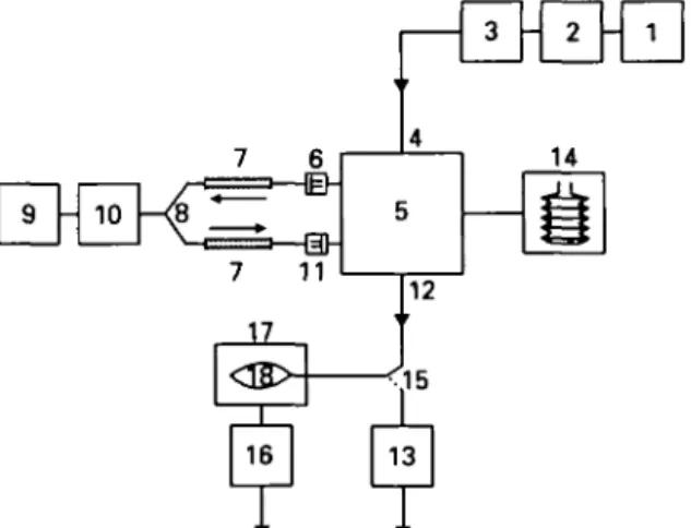
The experimental plan is depicted in figure 1. Fresh gas was supplied from a cylinder with a gas mixture of 95 % oxygen and 5 % carbon dioxide. Before each set of measurements, the inflowing concentration of carbon dioxide was measured using an infra-red gas monitor (Capnomac, Datex, Helsinki, Finland). FGF was set at 1.0, 3.0, 6.0, 8.0 and 10.0 litre min"1 using a flowmeter
cali-brated for oxygen (Dragerwerke AG, Liibeck, FRG). The accuracy of this flowmeter was checked using a bell spirometer (Gould Godart Expirograph, Gould Medical B.V., Bilthoven, The Netherlands) and was found to be within ± 10% of the actual reading at all flows. The carbon dioxide absorber in the circle system was filled with silica gel beads (Kieselgel 2-5 mm Art. 7735, E. Merck, Darmstadt, FRG) to remove humidity which could affect gas volume measurement. The resistances and effective gas spaces of a container with these silica gel beads and one with ordinary soda-lime (Dragersorb 800, Dragerwerke AG,
Lubeck, FRG) were measured and found to be comparable: at a dry air flow of 60 litre min"1
through the container, the resulting pressure at the inlet port was 0.032 kPa both for soda-lime and silica gel beads.
A second container filled with soda-lime 1 litre (Dragersorb 800) was placed between the Y-piece and the test lung. This absorber was tested and found to eliminate all carbon dioxide reaching the patient. The test lung was a Drager LS 800 (Dragerwerke AG, Lubeck, FRG) with a cuffed 8.5-mm oral tube (Rusch AG, Waiblingen, FRG) with the following nominal settings: resistance 0.4 kPa litre"1 s, compliance 0.6 litre kPa"1,
leak-age 0 litre s"1. At the scavenging port a reservoir
bag (2-litre for FGF 1.0 litre min"1, 5-litre for
FGF 3 litre min"1 and 15-litre for FGF 6, 8 and
10 litre min"1) was attached via a corrugated hose
and filled with exhaust gas. This bag was mounted into a rigid container made from plastic material and allowed to fill without pressure. The container was gastight to the interior of the reservoir bag and to the environment. At a second port of the container the anaesthetic gas scavenging system (AGSS) was connected. This arrangement
de-7 6 9 - 10 7 11 4 5 3 - 2 14
n
- 1 17<s>
I 16+
13T T
FIG. 1. Experimental plan to measure fresh gas utilization. 1 = Cylinder with premixed gas; 2 =• flowmeter for adjusting and measuring the FGF; 3 •= measuring device for con-centration of carbon dioxide in the fresh gas; 4 = fresh gas inlet port; 5 = circle system in evaluation, with carbon dioxide absorber filled with silica gel beads; 6 = inspiratory uni-directional valve; 7 = breathing tube; 8 = Y-piece; 9 = test lung; 10 = carbon dioxide absorber; 11 = expiratory unidirec-tional valve; 12 = exhaust port; 13 = measuring device for concentration of carbon dioxide in the exhaust gas; 14 = ventilator; 15 = switch-over valve in position "filling reservoir bag"; 16 = scavenging system; 17 = rigid container; 18 =
coupled the breathing system from the AGSS, but allowed for pressure influences of the AGSS on the breathing system (by flow and pressure). From the reservoir bag, the well mixed gas was extracted and the mean concentration of carbon dioxide measured using the sideline infra-red gas monitor (Capnomac).
The breathing system was connected to the Y-piece (DAR 600/5086) at the test lung with two breathing tubes (1.0 m in length) (DAR 280/5048, Darex S.P.A., Mirandola, Italy). The measured compliance of each of these tubes was 4.4 ml kPa"1
(measured at a pressure of 2 kPa).
All breathing systems were tested for leakage before measurements were made [4]. At each flow setting, measurements were started after a period of three time constants. A time constant was defined as the circle system volume divided by FGF. The volume of each system was measured including filled absorber, breathing tubes and Y-piece. For the volume measurement, the circuit was sealed completely and a known volume of gas was added. By measuring the increase in pressure, the circuit volume could be calculated. As the soda-lime absorber at the Y-piece became partly consumed during measurements, a small dead-space developed, its size depending on the duration of the measurements. Thus exactly the same time course of measurements was followed for all systems. To compensate for the deadspace, a system volume of 5 litre (which was greater than all the measured volumes) was assumed. For example, FGF 1 litre min"1 required a waiting
period of 15 min. To avoid further deadspace in the soda-lime at the Y-piece, fresh soda-lime was used for each change of fresh gas flows. All measurements were performed three times in succession with freshly filled carbon dioxide absorber at each of the five flow settings, resulting in a total of 15 measurements for each system.
The ventilators were adjusted to the following settings: tidal volume 800 ml; ventilatory fre-quency 10 b.p.m.; I:E ratio 1:2; inspiratory flow at the least value necessary to achieve a tidal volume of 800 ml with the I:E ratio of 1:2; zero PEEP.
As the tidal volumes of Drager 8 ISO, Ohmeda Modulus II Plus and Siemens Ventilator 710 depend on the fresh gas flow, tidal volume was set using a pneumotachograph (accuracy ± 5 % , Megamed 0577, Megamed AG, Cham, Switzer-land) before each measurement. During measure-ments the pneumotachograph was removed from
the circuit. The tidal volumes of the Drager Cicero, the Drager AVI, the Gambro Engstrom Elsa, the Siemens Servo Ventilator and the Megamed 700A, which are FGF independent, were also measured with this device. A constant deadspace of 50 ml between the Y-piece and the soda-lime canister was maintained.
FGU was calculated using the following equa-tion:
F"1~F°u t
FGU = x 100 %
where: FGU = fresh gas utilization (%); FlD =
carbon dioxide concentration measured at the fresh gas inlet (vol % ) ; Foat = carbon dioxide
concentration measured in the reservoir bag (vol %)•
A FGU of 100% implies that all fresh gas reaches the patient.
Because of the difficult working principles of the eight circle systems, it was necessary to choose different settings. In the systems in which the carbon dioxide absorber is placed either in the inspiratory or the expiratory limb (Drager AVI and Gambro Engstrom Elsa) we placed the "dummy" absorber canister in the inspiratory limb. Adjustable pressure limit valves (APL valves) were closed totally or set to the greatest possible value. Only the exceptions in the adjust-ments or important details are mentioned under the different systems.
Drdger Cicero: To set the inspiratory flow to the
smallest value to achieve a tidal volume of 800 ml, the inspiratory pause was set to zero. Drdger 8
ISO: The circle system 8 ISO has two inlet ports
for fresh gas; both settings were measured. The inlet port between the ventilator port and the carbon dioxide absorber is recommended by the manufacturer. The other inlet port would be between the carbon dioxide absorber and the inspiratory unidirectional valve. The changeover valve (which is a switch at the exhaust port and is used mostly during manual ventilation) was set to the horizontal position. Drdger A VI: The stan-dard fiowmeters of the ventilator, which are calibrated for a mixture of oxygen and nitrous oxide, were used. Ohmeda Modulus II Plus: The inspiratory flow and the I:E ratio cannot be adjusted independently. There is only one knob for setting the inspiratory flow to obtain the required I:E ratio. The inspiratory flow was thus set to obtain an inspiratory pause of 0 %. Gambro
electron-ically controlled fresh gas mixing system (elec-tronic mass flowmeter). The pump for the implemented anaesthetic agent monitor, which continuously aspirates 200 litre min"1, was
switched off. Siemens Servo Ventilator: The inspiratory flow cannot be adjusted separately. We set the inspiration time to 25 % of the time of one ventilatory cycle (this resulted in a more accurate i: E ratio of 1:2 than when selecting the position marked with 33 %). The Serve Ventilator has its own fresh gas delivering system which adds fresh gas only during inspiration to the circle system. At FGF values greater than that of minute volume, the ventilator works as a semi-open system. Siemens Ventilator 710: The inspiratory flow cannot be adjusted separately. We set the inspiration time to 33% of the time of one ventilatory cycle. Megamed 700A: The Megamed circle system has a manually adjustable overflow valve which can be set to three arbitrary positions. Depending on FGF, we chose a position which allowed the reservoir bag to become slightly filled; the tidal volume was then independent of FGF. Position 0.5 was selected for FGF 1 litre min"1,
position 1 for 3 litre min"1 and position 2 for 6, 8
and 10 litre min"1.
RESULTS
The measured system volumes were: Drager Cicero 3600 ml, Drager 8 ISO 1800 ml, Drager AVI 1700 ml, Ohmeda Modulus II Plus 4900 ml, Gambro Engstrom Elsa 1800 ml, Siemens Servo Ventilator 2100 ml, Siemens Ventilator 710 1700 ml and Megamed 700A 2300 ml.
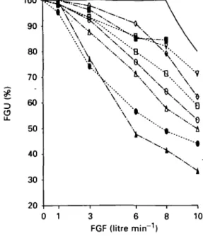
Figure 2 depicts FGU of the eight systems in relation to FGF. All systems were less efficient than an ideal system, which would have an FGU of 100 % for an FGF less than the ventilatory minute volume. For FGF values greater than that of the minute volume, the ideal FGU is the ratio of minute volume to FGF. In this consideration the system compliance is not taken into account. Table I lists the respective FGU at FGF 3 litre min"1, which is a standard clinical setting.
The Drager 8 ISO improved considerably when the fresh gas inlet was mounted after the soda-lime absorber (table II).
FGU decreased rapidly in all systems when FGF greater than 3 litre min"1 were used. Figure
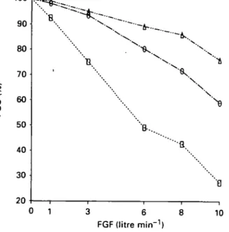
3 shows the FGU of the Drager Cicero ventilator at different tidal volumes (400 ml, 800 ml and 1200 ml) and the same ventilatory frequency
100 90 80 70 60 50 40 30 20
v •*.
o 1 3 6 FGF (litre min"1) 10FIG. 2. Fresh gas utilization (FGU) for the anaesthesia breathing systems as a function of fresh gas flow (FGF). • = Drager Cicero; O = Dragcr 8 ISO; A = Draper AVI; V = Ohmeda Modulus II Plus; O = Gambro Engstrom Elsa; • = Siemens Servo Ventilator; • = Siemens Ventilator 710; A
= Megamed 700A; = ideal.
TABLE I. Fresh gas utilization (FGU) at a fresh gas flow of 3 litre min'' (mean (SEM))
Circle system FGU (%) Drfiger Cicero 93.4 (0.31) Drager 8 ISO 92.3 (0.26) Drager AVI 87.6 (0.33) Ohmeda Modulus II Plus 93.1 (0.50) Gambro Engstrom Elsa 97.8 (0.07) Siemens Servo Ventilator 96.1 (0.35) Siemens Ventilator 710 74.1 (0.62) Megamed 700A 77.0 (0.56)
TABLE II. Fresh gas utilization (FGU) in the Drdger 8 ISO circle system with the gas inlet positioned before or after the
soda-lime canister FGU (%) F G F (litre min"1) 1 3 6 8 10 Inlet before absorber 98.7 92.3 76.0 64.5 53.3 Inlet after absorber 100 97.9 84.9 75.0 57.7
BRITISH JOURNAL OF ANAESTHESIA 100 ^ 90 80 70 3 60 u. 50 40 30 20 " ''B-... 10 FGF (litre min"1)
FIG. 3. Fresh gas utilization (FGU) for the circle system DrSger " Cicero " at tidal volumes 400 ml ( • ) . 800 ml (O) and 1200 ml (A), and at a ventilatory frequency of 10 b.p.m.
(10 b.p.m.). At each FGF, FGU increased when the minute volume increased, this effect becoming more evident at greater FGF.
DISCUSSION
At small FGF which would be used clinically in a low-flow anaesthesia technique, all systems ap-proached almost 100% FGU. At greater FGF there was a marked difference between the systems (fig. 2).
The Siemens Servo Ventilator differs from all other circle system. The fresh gas is not flowing continuously, but only during inspiration into the circle system. Thus tidal volume is independent of FGF. For flows greater than minute volume, the ventilator bellow remains in its upper position and the ventilator works as a (semi-open) con-ventional Servo ventilator without recirculation of expired gases. For this reason, it is not possible to set the minute volume to 8 litre and provide a fresh gas flow of 10 litre min"1.
In an ideal system, all fresh gas would enter the circle during the expiratory phase and be directed to the patient during the phase of inspiration. In systems with a low FGU, such as Megamed and Siemens 710, the fresh gas inlet port is close to the exhaust port which allows fresh gas to escape
without reaching the patient. The Drager AVI would have a comparably small FGU if there was not a buffering chamber between the scavenging port and the fresh gas inlet (not shown in figure 4). In the Drager 8 ISO, fresh gas can escape only during mechanical ventilation through a valve near the bellows, which results in better FGU. In the Ohmeda II Plus, the arrangement is similar but the absorber is placed between the fresh gas inlet port and the overflow valve in the ventilator and this improves FGU. In the Engstrom ELSA, the fresh gas inlet port is separated from the overflow valve by the expiratory valve or in the inspiratory limb by the soda-lime absorber, both resulting in long pathways for the fresh gas and thus in high FGU values. The importance of separating the fresh gas inlet from the exhaust port is evident in the Drager 8 ISO: if the fresh gas inlet is mounted after the soda-lime canister (which is an option), FGU improves considerably. This position would also have the advantage that the volatile anaesthetic of the fresh gas is not absorbed by the soda-lime. The Cicero has many electronically controlled valves which should result in optimized FGU values; however, the performance of the system is slightly suboptimal because of the compact construction of the circle resulting in short pathways for the gases.
The described standard proposal test procedure appears to be simple, but this investigation has shown that attention to detail is important. System arrangement, system leaks, inflowing concen-tration of carbon dioxide, compliance of the tubing, minute volume, soda-lime and the equi-libration period for each measurement are im-portant variables. The system arrangement may be important as it may affect resistance to gas flow. Gas leaks inevitably lead to inaccurately great FGU. For this reason, the standard requires a leakage smaller than 50 ml min"1. All systems
used in this study fulfilled this criterion as was shown in a separate study [4]. Another cause of gas loss is the carbon dioxide absorbed; thus the standard proposal prescribes a denned inflowing gas concentration of carbon dioxide 6 vol %; in this study, only 5 % was available. Compliance of the tubing may influence FGU as well. When highly compliant tubes are used, part of the tidal volume is lost in tube expansion. According to the draft in this study, the same breathing tubes were used for all systems. Ventilation is a further important factor: the greater the minute volume, the greater is FGU. In this study, tidal volume
was measured because in some ventilators tidal volume depends on FGF. In the Cicero, AVI, Gambro Engstrom Elsa and Megamed, the tidal volume is independent of the amount of inflowing gas. This allows for constant tidal volumes despite changes in FGF. "Alveolar" ventilation may be reduced by deadspace which develops when part of the lime is used up. In this study, soda-lime was changed before each measurement. For the same FGF, the same time constant had to be assumed for all systems, and thus it is assumed that the increasing deadspace in the soda-lime influenced the results to the same (small) extent for all systems.
In an earlier publication, Eger and Ethans investigated the effects of system arrangement on the elimination of alveolar gas [2]. They found that the FGU of various circle arrangements varied greatly, depending on whether ventilation was spontaneous or controlled. Furthermore, an impact of the breathing pattern was important. These factors could not be tested in the present study.
APPENDIX
DESCRIPTION OF THE CIRCLE SYSTEMS
(fig. 4)
Drdgtr Cicero
The tidal volume is independent of fresh gas inflow. During inspiration, valve 12 is closed and fresh gas is directed into the reservoir bag (6). The ventilator (8) consists of a horizontally positioned piston which is driven electromechanically. The overflow valve (9) is closed during inspiration. All valves (except the inspiratory valve (1) and expiratory valve (2), which are passive ceramic disc valves) are controlled electro-pneumatically.
Drdger 8 ISO
The tidal volume is dependent on fresh gas inflow. The ventilator (8) consists of a pneumatically controlled hanging bellows. The overflow valve (9) is placed at the ventilator Ventilog and is closed during inspiration. The mechanically adjustable PEEP-valve (7) is placed at the ventilator Ventilog. The valves (except inspiratory valve (1) and expiratory valve (2), which are passive ceramic disc valves) are controlled pneumatically. The exhaust port for mechanical ventilation is at the ventilator Ventilog.
Dr&gcr AVI
The tidal volume is independent of fresh gas inflow. Valve 12 and the PEEP valve (7) are built together. During inspiration, this unit is closed and fresh gas flow is directed
into the reservoir bag (6). The ventilator (8) consists of a pneumatically controlled hanging bellows. The overflow valve (9) is dosed during inspiration. All valves (except inspiratory valve (1), expiratory valve (2) and both valves 13, which are passive ceramic disc valves) are electropneumarjcally con-trolled. Valve 13 between the ventilator (8) and the reservoir bag (6) is necessary to direct the gas to the patient during inspiration. Valve 13 between the reservoir bag (6) and the fresh gas inlet port (3) is necessary for manual ventilation with the reservoir bag.
Ohmeda Modulus 11 Plus
The tidal volume is dependent on fresh gas inflow. The ventilator (8) consists of a pneumatically controlled standing bellows. The overflow valve (9) is closed by the driving pressure of the bellow during the inspiration. PEEP cannot be set. The inspiratory valve (1) and expiratory valve (2) are passive disc valves.
Gambro Engstrdm Etta
The tidal volume is independent of fresh gas inflow. The ventilator (8) consists of a pneumatically controlled reservoir bag (bag-in-bottle principle). The inspiratory and expiratory flows are measured by differential pneumotachographs. The fresh gas is given continuously into the circle system. The inspiration lasts until the desired tidal volume (measured by the inspiratory flowmeter) has been delivered. All valves (except the inspiratory valve (1) and expiratory valve (2), which are passive rubber disc valves) are controlled electro-pneumatically.
Siemens Servo Ventilator
The tidal volume is independent of fresh gas inflow, provided minute volume is greater than FGF. The ventilator (8) consists of a pneumatically controlled standing bellows. The necessary amount of fresh gas is computed and delivered into the circle system only during inspiration. The bellows position is measured optically. The overflow valve (9) is closed during inspiration. The valves (except the inspiratory valve (1), which is a passive disc valve) are controlled electro-pneumatically.
Siemens Ventilator 710
The tidal volume is dependent on fresh gas inflow. The ventilator (8) consists of a pneumatically controlled reservoir bag (bag-in-bottle principle). Valve 12 and the PEEP valve (7) are built together. The overflow valve (9) is closed during inspiration. This circle system has two inspiratory and two expiratory valves, which is functionally not necessary. The valves (except inspiratory valve (1) and both valves 13, which are passive disc valves) are controlled clectropneumarjcally. Megamed 700 A
The tidal volume is independent of fresh gas inflow. The inspiratory pressure closes the expiratory valve (2) pneu-matically during inspiration, otherwise the reservoir bag (6) would be ventilated. The passive unidirectional valve 13 is necessary to direct gas to the patient during inspiration. This valve is bypassed in the manual mode. The fresh gas flows continuously into the reservoir bag (6). The overflow valve (9) is adjustable manually.
498
Drager 'Cicero' IPPV Draper "8 ISO' IPPV
-( 3 Fresh gas Fresh gas
Scavenging 11
• Scavenging
Drager 'AVT1 IPPV Ohmeda 'Modulus II Plus" IPPV
Fresh gas 3 3 Fresh gas
Scavenging
Gambro Engstr6m "ELSA1 IPPV
"•• Scavenging
Siemens "Ventilator 710' IPPV
11Scavenging
Siemens 'Servo Ventilator' IPPV 3 Fresh gas
Scavenging
Meeamed '700A' IPPV
13 1 0 , 1 Fresh gas
Scavenging
10 13 3 Fresh gas
11 11 FIG. 4. For legend see facing page.
FIG. 4. Simplified schematic diagram of the different circle three anesthesia circle systems. Anesthesia and Analgesia systems. 1 = Inspiratory valve; 2 = expiratory valve; 3 = 1976; 55: 724-729.
fresh gas inlet port; 4 = breathing tube; 5 = Y-piece; 6 = 2. Eger El, EthansGT. The effects of inflow, overflow and reservoir bag; 7 = PEEP valve; 8 = ventilator; 9 = overflow valve placement on economy of the circle system, valve; 10 = carbon dioxide absorber; 11 = scavenging port; Anesthesiology 1968; 29: 93-100.
12 = valve; 13 = unidirectional valve. 3. Comite Europeen de Normalisation. CEN/TC 215/WG1
N36 : Anesthetic Workstations and Their Modules, Version
0.32. September 18, 1990.
4. Leuenberger M, Feigenwinter P, Zbinden AM. The gas REFERENCES leakage of six anaesthesia circle systems. European Journal 1. Harper M, Eger El. A comparison of the efficiency of of Anaesthesiology 1991; (in press).