Content-Adaptive Bi-Level (Facsimile) Image Coding
byNeil H. Tender
S.B., Massachusetts Institute of Technology (1993)
Submitted to the Department of Electrical Engineering and Computer Science
in partial fulfillment of the requirements for the degree of
Master of Science in Electrical Engineering and Computer Science
at the
MASSACHUSETTS INSTITUTE OF TECHNOLOGY
May 1994
( Neil H. Tender, MCMXCIV. All rights reserved.
The author hereby grants to MIT permission to reproduce and to distribute copies
of this thesis document in whole or in part, and to grant others the right to do so.
Author
...
...
...
.. ...
Department of Electrical Engineering and Computer Science
May 13, 1994
Certified by . . .1 ., -
_
....
..
...
...
..-
....
David H. Staelin
Professor of Electrical Engineering
Thesis Supervisor
Certified
by ... ...
.
...
Dr. Forrest Tzeng
Comsat Laboratories
Company Supervisor
A -4-onrl h-... . .. ... .. . .. . . . .. ...Frederic R. Morgenthaler
Committee on Graduate Students
~~~~Uy
...Content-Adaptive Bi-Level (Facsimile) Image Coding
by
Neil H. Tender
Submitted to the Department of Electrical Engineering and Computer Science
on May 13, 1994, in partial fulfillment of the
requirements for the degree of
Master of Science in Electrical Engineering and Computer Science
Abstract
The high bandwidth requirements of facsimile communication can make it very costly or even infeasible in environments where these resources are limited. The existing CCITT Recommendation T.4 standard uses lossless Group 3 compression to reduce the number of
bits by a factor of 6 to 12, depending upon the contents of the document. However, with the
rapidly increasing use of facsimile equipment, a large number of communications services
could benefit greatly from an additional reduction in bandwidth.
This thesis describes the development of such an improved coding technique, called Content-Adaptive Facsimile Coding (CAFC). It uses a more sophisticated page model that better
represents the types of documents that are typically transmitted via facsimile. Three
dif-ferent coding techniques (Symbol Matching and Substitution, Optimized 2D Run-Length Coding, and non-compressing Direct Coding) are adaptively applied to different parts of the page, followed by a stage of arithmetic coding. CAFC achieves compression ratios that outperform Group 3 by an average of almost 2:1 for most documents and 3:1 for documents consisting predominantly of typed text (25% improvement over JBIG for text). In addition, preliminary estimates show that by using concepts from JBIG to replace the run-length cod-ing, there is the potential for an additional 2:1 improvement for most non-text documents.
Although the algorithm is lossy, there is little perceivable distortion introduced into the
reconstructed images.
In this research, the target application for CAFC is secondary facsimile compression within
Digital Circuit Multiplication Equipment (DCME). The methods developed have the
poten-tial to double the capacity of DCME equipment for facsimile transmissions at the expense of a very small amount of image distortion. The amount of additional hardware that would be needed to implement CAFC on DCME facsimile channels is believed to be of the same order of magnitude as that used on existing speech channels.
Thesis Supervisor: David H. Staelin Title: Professor of Electrical Engineering Company Supervisor: Dr. Forrest Tzeng
Acknowledgments
There are so many people to thank, I don't know where to begin! I did my thesis work at
both Comsat and MIT and interacted with so many people; it is hard to select only a few
to acknowledge. Let me start by thanking the numerous people whose names cannot fit in this small space. You know who you are!
Mom and dad, I cannot begin to count the number of ways which you helped me get through it all. You have truly always been there when I needed you, ready to do anything in your power to make things go well for me. There are no words powerful enough to express my gratitude. And Kim, whenever I start feeling old, you make me feel young again by
reminding me our our experiences growing up together.
I know that my beloved Grandma Saire, wherever she may be right now, is watching over me saying "That's my MIT boy!" I could never imagine a grandmother more proud, and there is no question that it is her dignity that has kept me going over the years. She will never be forgotten.
Jon and Jason, we've been together all along, from our freshman "quad" to the completion
of our masters theses. It's hard to believe just how many things have changed and even
harder to believe how many have stayed the same. We have gone through so much together; thanks for being there when I needed you!
To my many other friends from MIT: Steve, who is constantly reminding me how nice Maryland is; Karl and Dave, who always enjoy a good "jam" and have kept the music flowing; Marcie, Teresa, and Tracy, who keep track of whose birthday we need to celebrate next. You have all been an important part of my college years.
When working on a project intensely, it is important to take breaks. For helping me occasionally forget about my thesis altogether, I have to give credit to my friends who
are not from MIT, particularly Arthur, Duane, Paul, Becky, and Jenisa. Thank you for
reminding me that work is not the only part of life.
Sometime back in the Spring of 1993 I cracked open a fortune cookie that promised "You will soon get something you have always wanted." Well, that fortune came true. During my final eight month 6A assignment, I learned about something far more important than fax compression - physical fitness. I started running regularly and eating healthy and got in shape for the first time in my life. I would like to thank all of my running partners who helped me make one of the biggest changes in my life: Dad, Frank, Udaya and Rod, Jeff, and more recently, Jon.
I would like to thank all of those who made the whole 6A experience possible. My advisor at MIT, Professor Staelin, and all of my former Comsat advisors, Forrest Tzeng, Rod Ragland, and Udaya Bhaskar, have helped make my assignments incredible learning experiences. Thanks also to the many people at Comsat who have contributed in their own ways. Finally, I would like to thank Professor Papadopoulos, my undergraduate thesis advisor, who always makes everything so fun and exciting, reminding me just why I went into engineering in the first place.
Contents
1 Introduction
1.1 Facsimile Compression for DCME
2 Overview of CAFC
2.1 Contents and Coding Techniques
3 Page Modeling and Analysis
3.1 Symbol Detection and Isolation
3.1.1 Symbol Filling. 3.1.2 Symbol Tracing . 3.1.3 Symbol Windowing ...
3.2 Dithered Bitmap Detection
4 Coding Techniques
4.1 Symbol Matching and Substitution ...
4.1.1 Feature Extraction and Matching ...
4.1.2 Template Matching .
4.1.3 Library Maintenance .
4.2 Optimized 2D Run-Length Coding ... 4.3 Direct Coding ...
5 Multiplexing and Arithmetic Coding
5.1 Content Multiplexing .
5.2 Arithmetic Coding.
5.3 Adaptive Arithmetic Coding Models ...
5.4 Arithmetic Coding Model for CAFC ...
11 12 15 17
19
21 23 24 25 2628
28 31 33 34 35 3940
40 42 45 46...
...
...
...
...
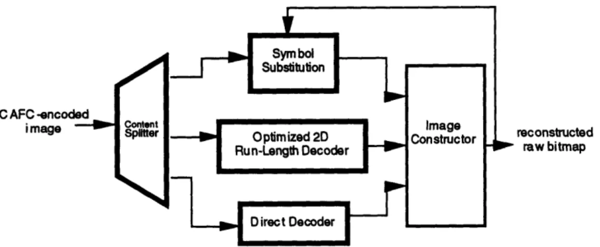
6 CAFC Decoder
7 CAFC Parameter Optimization
52
7.1 Selection of Symbol Isolation Technique ... 53
7.2 Feature Selection and Matching Criteria ...
.
54
7.3 Template Matching Criteria ...
57
7.4 2D Run-Length Coding Initial Model . . . 59
8 Analysis and Evaluation
60
8.1 Compression Gains ... 618.2 Reconstructed Image Quality ... 63
8.3 Computational Resources ... 64
8.4 Coding Delay ... 65
9 DCME Implementation Issues
66
9.1 Variable Bandwidth Output . . . ... 669.2 Coding Delay ... 68
9.3 Forward Error Correction . . . ... 69
10 Conclusion and Recommendations
72
10.1 Summary and Conclusion ... 7210.2 Improvements to Algorithm ... 73
Bibliography
76
A CCITT Test Images
78
B CAFC-Processed CCITT Test Images
87
C Typed Text Test Images
96
D Training Set Images
102
E CAFC Software Implementation
111
E.1 Source Code - CAFC Parameters ... 114E.2 Source Code - CAFC Encoder ... 114
E.4 Source Code - Symbol Matching ... 126
E.5 Source Code - Feature Extraction . . . .... 128
E.6 Source Code - Symbol Library Management ... 132
E.7 Source Code - Symbol Isolation ... 134
E.8 Source Code - Symbol Manipulation ... 144
List of Figures
1-1 Proposed DCME configuration with secondary fax compression. 1-2 Secondary facsimile compression over DCME. ...
2-1 CAFC block diagram ... 3-1 CAFC encoder block diagram ... 3-2 Example of symbol isolation ... 3-3 Symbol filling ..
3-4 Symbol tracing. 3-5 Symbol windowing .
4-1 Example of symbol matching.
...
4-2 Symbol matching and substitution encoder (with symbol isolator). 4-3 Run-length coding of a portion of a scan line...
4-4 Run-length statistics for a sample set of images. ... 4-5 2D run-length statistics for a sample set of images. ...
5-1 CAFC multiplexing state diagram.
...
5-2 Arithmetic coding state diagram.
...
6-1 CAFC decoder block diagram ...
7-1 Statistics of features on test symbols .
...
7-2 Reconstructed images at various template matching thresholds ....
A-1 CCITT test image #1 ...
A-2 CCITT test image #2 ...
A-3 CCITT test image #3 ...
.. . 14 14 16 20 22 24 25 26 30 32 36 37 38 41 48 50 56 58 79 80
A-4 CCITT test image #4 .
CCITT test
CCITT test
CCITT test
CCITT test
CCITT test
CCITT test
CCITT test
CCITT test
CCITT test
CCITT test
CCITT test
CCITT test
Typed text
Typed text
Typed text
Typed text
Typed text
Typed text
Typed text
Typed text
Typed text
image #5
image #6
image #7
image #8
image #1
image #2
image #3
image #4
image #5
image #6
image #7
image #8
image image image image image image image image image#1
#2
#3
#4
#5
#6#7
#8
#9
-D-1 Training set document #1
Training set
Training set Training set Training set Training setTraining set
Training set
document #2
document #3
document #4
document #5
document #6
document #7
document #8
83 84 85 86 88 89 90 91 92 93 94 95Courier 8pt
Courier 10pt . Courier 12pt .Times Roman
Times Roman
Times RomanHelvetica 8pt.
Helvetica 10pt Helvetica 12pt 97 97 98 98 99 99 100 100 101 . . . ..8pt ..
10pt 12pt .. . . . . . 103 . . . 103 . . . 104 . . . 104 . . . 105 . . . 105 . . . 106 . . . 106 A-5 A-6 A-7 A-8 B-1 B-2 B-3 B-4 B-5 B-6 B-7 B-8 C-1 C-2 C-3 C-4 C-5 C-6 C-7 C-8 C-9 D-2 D-3 D-4 D-5 D-6 D-7 D-8 82 . . . . . . . . . . . ....
...
...
. . . ....
...
...
...
...
...
...
...
...
...
...
...
...
...
...
...
D-9 Training set document #9 ... 107
D-10 Training set document #10 ...
107
D-11 Training set document #11 ...
108
D-12 Training set document #12 ...
108
D-13 Training set document #13 . . . ... 109
D-14 Training set document #14. . . . ... 109
D-15 Training set document #15 ... 110
List of Tables
2.1 Foreground content types and associated coding techniques ... 18
4.1 Potential features for feature matching. ... 33
4.2 Contents of a library entry. ...
35
5.1 Example fixed model for alphabet [a, b, c]. ... 44
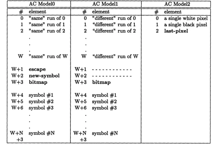
5.2 CAFC's three arithmetic coding models ... 47
7.1 Comparison of symbol isolation techniques. ... 53
7.2 Feature statistics - rejection threshold and effectiveness ...
57
7.3 CAFC coding performance at various template matching thresholds ... . 59
8.1 Compressed file sizes in bytes for various coding algorithms ... 61
8.2 Relative compression ratios for CAFC ... .. 62
8.3 Estimated file sizes for CAFC with suggested modification. ... 62
E.1 Summary of CAFC software modules. . . . 112
E.2 Summary of PCX file format modules ... 113
Chapter 1
Introduction
Facsimile (fax) communication has become increasingly popular over the past few years. As the number of fax pages transmitted each year continues to rise at an astonishingly high rate, the technique used for encoding the images becomes extremely important.
The biggest problem inherent to facsimile communication is that it requires the transmission
of a tremendous number of data bits. A single bi-level page of a fine resolution CCITT fax consists of close to four million pixels. Without any source coding, this transmission could tie up a 4800 bit/s channel for over 13 minutes. To reduce this burden, a facsimile image compression technique is employed. Most of the more popular facsimile machines and
personal computer (PC) plug-in cards support the CCITT Recommendation T.4 Group 3
[1] standard for document transmission. The Group 3 standard employs a modified form of Huffman run-length coding to reduce the transmission time by a factor of 6 to 12, depending
upon the contents of the document.
Although the CCITT facsimile protocols were initially designed to be used over the Public Switched Telephone Network (PSTN), the increasing demand for facsimile communications has made it available in a more diverse set of environments. Many of these communications media are very expensive or have severely limited bit-rates, making them economically infeasible or impractical for facsimile even with the existing compression. For example, in 1992, the transmission of a single page over a 4800 bit/sec Inmarsat-M mobile satellite
channel would have taken several minutes and cost between $10 and $20 [2].
This thesis describes the development of a secondary facsimile compression algorithm,
in-tended to further reduce the number of bits per page and thus decrease these bandwidth
requirements even more. The proposed Content-Adaptive Facsimile Compression (CAFC) technique consists of a more aggressive approach than T.4 Modified Huffman Run-Length Coding, using a sophisticated page model that is better-suited for the types of documents that are typically transmitted via facsimile. Unlike Group 3, which applies a single coding scheme uniformly over the entire page, CAFC makes use of three different techniques, each applied where it would be most effective to minimize the number of bits needed to repre-sent the page. The initial goal is to achieve a compression ratio of 20:1, about a factor of
2 greater than that attained by Group 3, with no degradation in the reconstructed image
quality.
Chapters 2-6 explain the fundamental concepts behind CAFC and describe the encoding and
decoding techniques in detail. Chapter 7 discusses the procedures developed for optimizing
the various adjustable parameters of the algorithm. Chapters 8 and 10 summarize the
results of extensive simulations and provide suggestions for future development work. The
remainder of this chapter and Chap. 9 discuss the initial target application for CAFC,
facsimile compression for Digital Channel Multiplication Equipment.
1.1 Facsimile Compression for DCME
Although CAFC could conceivably be used to improve the efficiency of any facsimile image
transmission or storage system, this thesis focuses on its application to Digital Circuit
Multiplication Equipment (DCME) [3]. DCME multiplexes hundreds of analog voice, data, and fax channels into a single high-speed digital channel for transmission over a satellite link. To maximize the number of channels that can be operating simultaneously, some form of bandwidth reduction is applied to each channel prior to multiplexing. Voice and data channels are digitized and then passed through suitable coders that achieve compression ratios of 2 or 4. Fax channels are actually demodulated to a digital baseband signal and
transmitting the same signal in the voiceband domain, but unlike encoded voice and data, Group 3-encoded facsimile is extremely sensitive to bit errors. In some DCME channels,
the bit error rate can approach 10
-3, high enough to severely distort any fax page. In order
to make DCME viable for facsimile communication, it is necessary to use some degree of
Forward Error Correction (FEC). This technique adds redundant bits to the data prior to
transmission so that the receiver can detect and correct most of the errors. FEC virtually
eliminates distortion to the page introduced by channel errors, but it has the undesirable
effect of increasing the number of bits that must be transmitted and thus the required
bandwidth.
The proposed solution to this problem is to add a secondary compression stage using CAFC
prior to the multiplexor and FEC stages. The extra compression would decrease the required
DCME channel bandwidth to a level at or below what it is without FEC and secondary
compression, effectively reversing the negative effects of FEC. Figure 1-1 contains a block diagram of the envisioned configuration. The fax pages are scanned and encoded with
CCITT T.4 Group 3 coding and then modulated within the facsimile terminal equipment.
The DCME equipment then demodulates the fax signals, applies the secondary
compres-sion and FEC, multiplexes the channels, and transmits everything over a high-speed digital
satellite link. The DCME on the receiving end splits the high-speed input into signals for each of the incoming channels. The facsimile channels are then passed through an FEC
error-correcting stage and the resulting CAFC-encoded signals are decoded and converted
back to Group 3, removing the secondary compression. Finally, these signals are
modu-lated and routed to the receiving facsimile terminal equipment, ready to be demodumodu-lated,
decoded, and printed.
The secondary compression consists of two stages, as shown in Fig. 1-2. At the transmitting end, the T.4-encoded document must first be decoded with an inverse Modified Huffman
Run-Length coder (T.4
- 1) into a raw bitmap, increasing the total number of bits of
approx-imately a factor of 10. Then, the image is compressed using CAFC, reducing the number of bits by approximately a factor of 20, a net improvement of 2:1. At the receiving end, the process is reversed. The CAFC-encoded image is expanded to a raw bitmap by an inverse CAFC coder (CAFC-1), and then the bitmap is encoded using T.4 so that the fax terminal equipment can receive it, an overall increase of 2:1 in the number of bits. In each
voice cha nnels data cha nnels fa csimil e cha nnels
Figure 1-1: Proposed DCME configuration with secondary fax compression. direction, a sufficient amount of buffering is required to store the intermediary raw bitmap format. However, because this is a real-time implementation, only a small portion of the page need be stored as a raw bitmap at any given time. This is desirable feature of the
Group 3 and CAFC algorithms, since it allows the memory requirements and propagation
delay to be minimized. Section 9.2 discusses the issue of propagation delay in real-time fax
implementations.
raw bitmap (-4000 Kbit/page) -Secondary Coder raw bitmap CAFC-encoded image (-200 Kbit/page) CAFC-encoded image (-2(X) Kbit/page) Secondary DecoderFigure 1-2: Secondary facsimile compression over DCME.
voice chan nels data chan nels facsimil e chan nels Inverse Modified
Huffman Run-Length Coding (T.4') T.4-encoded facsimile image (-400 Kbit/page) T.4-encoded reconstructed facsimile image (-400 Kbitlpage) Content-Adaptive Facsimile Coding (CAFC) Modified
Huffman Run-Length Coding (T.4) Inverse Content-Adaptive Facsimile Coding (CAFC ) C _ __ . . , I-YI··l Lnl·lnll··CI
Chapter 2
Overview of CAFC
Bi-level (facsimile) image coding consists of a page model and a coding technique that is ap-plied to the information contained in the model. Facsimile compression involves applying a
better model and/or coding technique so as to represent the image in fewer bits, effectively
eliminating the redundant information. CCITT Recommendation T.4 Group 3 Modified
Huffman Run-Length Coding [1] models the page as a sequence of black and white hori-zontal run-lengths. These values are coded using a form of Huffman variable-length coding, achieving a compression ratio of approximately 10:1. Group 3 is effective because typical fax documents consist of strings of black or white pixels with unbalanced run-length distri-butions that can be efficiently entropy-coded with variable-length codewords (see Sect. 4.2). It may seem that a compression algorithm designed to work well for "typical" documents but not for all documents would be undesirable since there is a loss of generality and lower degree of reliability. For example, it is actually possible for a Group 3-encoded image to
contain more bits than the corresponding raw bitmap representation. Unfortunately, what
appears to be a design flaw is actually an essential requirement. It is theoretically impossible to achieve compression without the use of a model that makes some assumptions about the contents of the page. In order for a compression algorithm to be effective, it is essential that this page model be a good match for the documents that are to be compressed. In fact, this is true when compressing any type of data, not just bi-level images.
- - -I - I
I CAFC Encoder I I CAFCDecoder
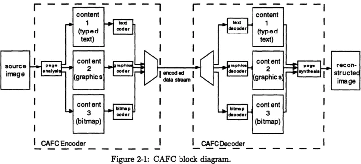
Figure 2-1: CAFC block diagram.
It should be evident that the assumptions that can be made about a source of data can best be determined by the means with which they were created. Many effective speech compression algorithms, for example, use a model of the human vocal tract to decompose
speech into a set of filter coefficients and some additional excitation information. While it
is not always possible to completely characterize a source, it is often acceptable to make sensible use of some known properties and develop a conservative model that performs extremely well when the assumptions are good yet is not completely ineffective when they are not.
This approach is the basis for Content-Adaptive Facsimile Coding. Facsimile documents typically consist of a large amount of typed text and some simple line graphics (diagrams), handwriting, and possibly some dithered bitmaps (grey-scale images converted to bi-level). CAFC uses a page model that classifies each of these elements as a different type of "fore-ground content." This representation is useful because each type of fore"fore-ground content has its own unique properties and can be modeled and coded most efficiently in a distinct man-ner. CAFC encodes a document by breaking the page down into its different foreground contents, encoding each with a technique optimized for the properties of that content, and then multiplexing all of the encoded data into a single data stream. To decode the
im-age, the data stream is separated back into its different content-specific parts, and then
each content is decoded and combined together to form the reconstructed page. Figure 2-1 illustrates the general flow of data during each of these stages.
r- - -
The important feature of CAFC is that the individual foreground contents are processed independently of one another, allowing the use of completely different coding methods. Each type of content is effectively modeled and coded differently, where the model is adaptively chosen by some local properties of the source image (hence the name Content-Adaptive Facsimile Coding). This differs fundamentally from Group 3 coding, which applies the same model and coding technique to the entire page. It is observed that the various foreground
contents that appear in facsimile documents have significantly different properties, and it
is therefore expected that an adaptive coder will achieve significantly higher compression.
2.1 Contents and Coding Techniques
For small and detailed image material, Group 3 achieves significantly lower compression
ratios than it does on most other documents. Yet, typed text, which fits into this category,
is the most prevalent foreground content in typical facsimile documents. For this reason, the primary focus of this thesis is the development of a sophisticated Symbol Matching
and Substitution algorithm optimized for compressing typed text. It is expected that this
technique alone will provide most of the compression for CAFC. On the other hand, Group 3 compresses larger and coarser image material very well. For contents with these properties, such as handwriting and graphics, CAFC applies a run-length coding technique that is very similar to Group 3, but optimized for the somewhat different run-length probability
distributions present in these contents. The CAFC method also takes into account the
two-dimensional redundancies on the page and employs an entropy coding technique known as arithmetic coding (AC) to provide additional compression over Group 3. Finally, for dithered bitmaps, Group 3 is an extremely ineffective coding technique; often, the image is actually expanded. To prevent this, CAFC directly encodes the pixels as individual bits without employing any entropy coding.
The CAFC content classifications and associated coding schemes, summarized in Table 2.1, were carefully selected to not only provide as high a compression ratio as possible, but to
also comprise a compression system that is practical and reliable. All of the algorithms
Foreground Content Coding Technique
Typed Text
Symbol Matching and Substitution
Graphics Optimized 2D Run-Length Coding Handwriting Optimized 2D Run-Length Coding
Dithered Bitmaps
Direct Coding
Table 2.1: Foreground content types and associated coding techniques.
probably indistinguishable from the originals. The use of a run-length coding variant as
one of the coding schemes guarantees that the compression ratio achieved by CAFC for any particular document will not be any lower than it would be with Group 3 coding. Likewise, the use of Direct Coding where appropriate guarantees that CAFC will never produce a coded image that is larger than the source. It is possible that a different set of foreground
contents and coding techniques could produce a higher compression ratio and/or better
image quality. Those listed in Table 2.1 were selected based upon the observed performance of existing facsimile compression techniques on a variety of documents.
Finally, it is necessary to mention that none of the components of Content-Adaptive Fac-simile Coding are completely original. A number of papers have been written about coding schemes similar to Symbol Matching and Substitution [4] [5] [6]. An even larger number of algorithms have been conceived for the efficient lossless two-dimensional coding of facsimile
[7] [8] [9] and for the encoding of dithered grey-scale images [10]. In fact, several standards have been introduced since Group 3, including two-dimensional Group 3, Group 4, and JBIG [11]. The content-based nature of CAFC is a relatively new idea that was taken from
some preliminary research performed at Comsat Laboratories [12]. However, that report
describes a hypothetical compression technique at a high level and does not go into sufficient detail to completely define an algorithm.
The work described in this thesis is an attempt to intelligently combine a number of these existing ideas into a practical working system that can improve the efficiency of facsimile transmissions. Each component is individually redesigned and optimized for use in an image compression system that could be incorporated into a real-time DCME platform. CAFC is
the unique combination of Symbol Matching and Substitution, Optimized 2D Run-Length
Chapter 3
Page Modeling and Analysis
As described in the previous chapter, a facsimile page is modeled as a combination of
sev-eral different types of foreground content - typed text, graphics, handwriting, and dithered
bitmaps. To keep things simple, graphics and handwriting are grouped together as a single
content because they have similar properties and share the same coding technique,
Opti-mized 2D Run-Length Coding. To encode a document, the CAFC encoder must scan the page (a raw bitmap) and divide it into a large number of small regions, each containing an
occurrence of a single content. The CAFC page model specifies exactly what constitutes a
region of a particular content so that the encoder's analysis algorithm can efficiently and
systematically break down the page into its components.
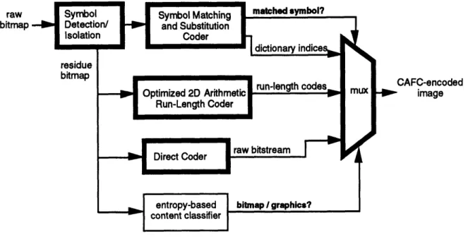
The content classification is performed progressively, as shown in Fig. 3-1. The encoder
first tries to detect instances of typed text, the content with the most efficient associated
coding technique. The basic element of typed text is the symbol, defined as a cluster of black pixels that is completely surrounded by white pixels. A symbol is essentially a single typed
character: a letter, a digit, a punctuation mark, or part of a character in cases where the
character consists of two or more segments, such as the percent sign (%). The encoder uses
a unique symbol detection/isolation algorithm to locate all such clusters and subsequently
codes them using the Symbol Matching and Substitution technique.
raw bitmap
CAFC-encoded image
Figure 3-1: CAFC encoder block diagram.
be free of typewritten text. An entropy-based content classifier examines each scan line of this image and searches for segments that would have unusually high entropies
(informa-tion contents) when represented with the two-dimensional run-length model. These scan
line segments are classified as dithered bitmap fragments because their run-length
distri-butions indicate that they contain a large number of very short run-lengths, a property
of dithered bitmaps. For now, Direct Coding simply inserts these pixels into the encoded bit-stream without any attempts at compression. All other segments are classified as the handwriting/graphics content and are coded with the entropy-based Optimized 2D
Run-Length Coder.
It is important to realize that these specifications were chosen to be practical and that the
CAFC encoder may not always be successful at correctly recognizing and categorizing each instance of a foreground content. For example, a detected symbol will not always turn out to be a typewritten character; a small handwritten number or part of a bitmap could easily qualify. Likewise, portions of the page with dense text or graphics might have high enough run-length entropies that they are classified as bitmaps. However, it is not particularly
important that the CAFC criterion for typed text, handwriting, graphics, and bitmaps
exactly match the perceptual significance of these contents. The primary objective for
content-based modeling. As long as the page model exploits the common properties of the majority of facsimile images, it is accomplishing this objective. Designing a page model that is as close to the perceptual level as possible is beneficial because it indirectly takes advantage of these particular properties. In CAFC, this approach works especially well since the characteristics that are sought out during the content classification are the same ones that are used to perform the actual coding. For example, the symbol-based model that is used for typed text allows for very efficient coding via Symbol Matching and Substitution. Similarly,
the criterion that is used for locating dithered bitmap fragments also guarantees that a
classification leading to the optimal coding method is made.
The progressive nature of CAFC is a very important aspect of this approach. Of the three
coding techniques used in CAFC, the Symbol Matching and Substitution coding technique
provides the greatest compression gains. For this reason, the encoder first attempts to
detect symbols in hopes that typewritten text will be discovered, so that Symbol Matching and Substitution can be applied. Then, after the symbols have been removed, entropy-based content classifier scans the page for instances where Direct Coding would be most efficient, most likely dithered bitmaps. Finally, Optimized 2D Run-Length Coding, the "default" technique, is applied to the remainder of the page, which is assumed to consist
of handwriting and graphics. Thus, by performing the content detection algorithms in this
specific order, the maximal compression can be achieved.
3.1 Symbol Detection and Isolation
The symbol isolator has the specific task of extracting all symbols from an image, making
them available for coding with Symbol Matching and Substitution. The objective is to detect
all isolated instances of contiguous black pixels (clusters of black pixels surrounded entirely
by white pixels) that meet some predetermined minimum and maximum size constraints.
Figure 3-2 contains an example of a portion of an an image where all of the symbols have been isolated and removed. In this case, the minimum allowed symbol size (widthxlength) was 2x3 pixels and the maximum allowed symbol size was 40x60 pixels.
v-- 2
_
[To+
I- f+
f
T ? al Et tctte phue at bium roppos de d4 ,
A ni ddpmmp cosmtant pri (uns importance)
et uo reted To prs (nfvitablo).
_ Un sialt ie S(t) trveant un tel fie adaptd
douA las so rtit (i u retard T 'pris et h un
ddphs-up prm de Is poo.) un signal dont Is tramoruAe
F.
2 de Fourier at rdb, coatante entro fi t A+4f,
et nal de part d'autr e def, t de +_ + /,
cest--dr un sial de frequce porteus? Ao+4t2 t
original
-I
IE
r
1
1
typed text removed
Figure 3-2: Example of symbol isolation.
the symbol isolation algorithm. It is required for a number of reasons, but primarily to
minimize the amount of propagation delay in CAFC so that it may be incorporated into a real-time facsimile transmission system (see Sect. 9.2). If, while investigating a possible symbol, the maximum allowable horizontal or vertical dimensions are exceeded, the isolation
is abandoned and the next potential symbol is pursued. Each of the three different isolation
techniques has a unique method for detecting this condition. A minimum symbol size is also imposed, since Symbol Matching and Substitution would not efficiently code very small symbols. The maximum and minimum symbol sizes are fixed and determined in advance. Whenever the symbol isolator successfully locates a symbol, it is immediately removed from
the page (so that it will not be detected again) and is then passed on to the coder. When
the symbol isolation procedure is complete, what remains on the page consists of white space and clusters that are too small or too large to be symbols.
When encoding an image, the CAFC encoder systematically scans the image from left to
L
i
I I
right and from top to bottom until it encounters a black pixel. The coordinates of this
pixel are used as the starting point for the detection and isolation of a symbol. Because it is a fairly involved process, three different methods for performing symbol isolation have been developed: symbol filling, symbol tracing, and symbol windowing. The approaches
differ in terms of their computational burden, memory requirements, and overall ability to
detect all of the symbols in an image. Section 7.1 describes the procedure for evaluating the performance of each technique and selecting the best one for CAFC. The following sections explain simplified versions of each of the three approaches. The actual real-time algorithms that were developed for CAFC are omitted from this discussion because they are considerably more tedious.
3.1.1
Symbol Filling
With symbol filling, the isolator examines each of the starting pixel's eight adjacent
neigh-bors and selects only those which are black. Then, each of the selected pixels are checked for adjacent black pixels in the same manner. This procedure is applied recursively until the entire cluster of contiguous black pixels has been isolated. When a black pixel is
de-tected, it is also marked so that the isolator will not detect it again and get stuck in an
infinite loop. If the rectangular region spanned by the cluster of marked pixels is within the
permitted range of sizes, a symbol has been detected. Otherwise, the pixels are left behind for subsequent coding by one of the other coding techniques.
Figure 3-3 contains an example of symbol filling. The numbers on each arrow indicate the
order in which the black pixels are detected and marked. In this case, the isolator examines
the neighboring pixels in the clockwise direction, starting with the pixel immediately to the
right. Thus, if the first black pixel is at coordinate (x,y), the isolator examines the eight neighboring pixels in the following order: (x+l, y), (x+l, y-l), (x, y-1), (x-1, y-1), (x-1, y),
(x-1, y+1), (x, y+1), and (x+l, y+1).
Symbol filling is capable of detecting all of the symbols on the page correctly. However, it
has the disadvantage that it must inspect every black pixel in the symbol, requiring a lot
Figure 3-3: Symbol filling.
3.1.2
Symbol Tracing
The particular order in which the source page is scanned for symbols guarantees that the
initial black pixel will always be on the boundary of a potential symbol. In symbol tracing,
this pixel is used as the starting point for a contour trace. The isolator examines the pixel's
neighbors in a specific order to determine which is the next boundary pixel, moving in a
clockwise direction. The trace continues until the first pixel is encountered once again. If the
size of the traced region is within the permitted range, a symbol is detected, consisting of all of the black pixels within the boundary. Otherwise, these pixels are marked as non-symbols. Figure 3-4 illustrates the procedure for symbol tracing. Once again, the numbers on each
arrow indicate the order in which the contour is traced. At each stage of the trace, the
search for the next boundary pixel begins at the pixel one step clockwise from the previous pixel and proceeds in the clockwise direction. If the current pixel is at coordinates (x, y) and the search for the next boundary pixel goes past (x+l, y), pixel (x+l, y) is marked. Likewise, if the search goes past (x-1, y), pixel (x, y) is marked. In the figure, the marked pixels are designated with an X. After the trace is complete, the detected symbol consists of all black pixels contained within the horizontal segments formed by the marked pixels. This technique requires less processing power and memory than symbol filling, but it does not always produce exactly the same results as symbol filling. The isolated symbol consists
X
Figure 3-4: Symbol tracing.
of all black pixels enclosed by the boundary, and it is possible to have scenarios where the pixels are not all contiguous. This will occur when a smaller cluster, completely surrounded by white pixels, is enclosed by a contour of black pixels, such as in the character ©. Effec-tively, a smaller symbol is contained within the larger one. Despite this inconsistency with
the strict definition of a symbol, the performance of the symbol matching and substitution
should not necessarily be any worse than it would with a filling isolator.
3.1.3
Symbol Windowing
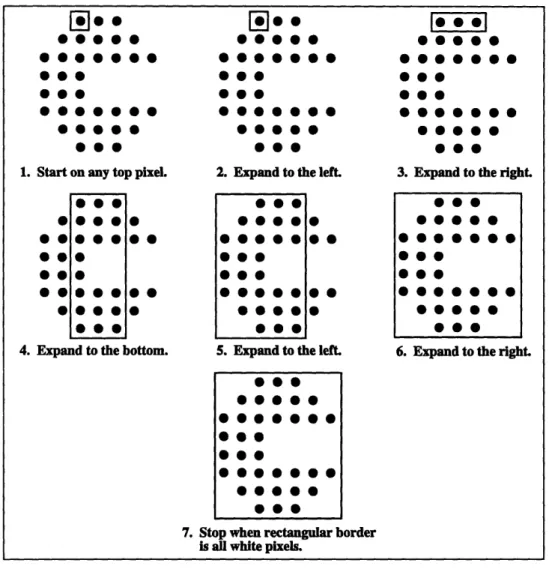
Finally, with symbol windowing, a rectangular window centered around the first detected
black pixel is used to surround the symbol. Initially the size of a single pixel, the rectangle
is gradually expanded in the horizontal and vertical directions until all of the pixels on its
four edges are white, or until the window is larger than the maximum allowed symbol size. At this point, the isolation is complete; if the window is within the permitted size constrints, a detected symbol is enclosed. Figure 3-5 illustrates an example of this process.
This approach is conceptually the most simple and straightforward and has very small
processing and storage demands. It is similar to symbol tracing in that it can sometimes
isolate "symbols within symbols", but this is not a problem from the coding efficiency perspective. The difficulty with symbol windowing is that a symbol can only be detected if it
1.
*
*
0 0
0 55 0 ·
0 0 0
4. Expand to the bottom.
* O · *@
* * O O
2. ES pand to the left
iwp
*]@@ @*@alwit
ies
0 0 00
3.550
0 @
@50Expand to the right
00 0
* 0 0 * 0
*
0 0000
*0
*0@0 0
* 0 *--
* · --* --* 06. Expand to the right.
Figure 3-5: Symbol windowing.
because each typed character is completely contained within its own rectangular region, but
there may be some fonts or styles (such as italics) where there can be overlap. The isolator could overlook many of the symbols or possibly group multiple symbols together, resulting in less efficient coding.
3.2 Dithered Bitmap Detection
Once all symbols have been isolated and removed, the remainder of the page is scanned
by an entropy-based content classifier to detect instances of dithered bitmap fragments.
The classifier is designed to locate portions of a scan line that would actually require more
bits to represent with Optimized 2D Run-Length Coding than with no compression at all
0
S S
(Direct Coding). To do this, it makes use of the same run-length statistics as the Optimized 2D Run-Length Coder (see Sect. 4.2) and estimates the entropy of each horizontal run in the image. Then, it looks for portions of scan lines where the average entropy per pixel is greater than one. These horizontal segments do not fit the run-length model very well and are therefore classified as dithered bitmap fragments which pass through the CAFC coder uncompressed.
Chapter 4
Coding Techniques
The following sections describe in detail the three coding techniques employed in Content-Adaptive Facsimile Coding. None of these methods are entirely novel approaches to bi-level image compression, but rather variations of previously developed methods that have been
improved and optimized for a particular content. They are all designed to produce decoded
content regions that in an error-free environment are either identical to the original or nearly indistinguishable, so that the reconstructed facsimile images are of high quality.
In terms of compression efficiency, each of the content coders serves a different role. The
Optimized 2D Run-Length Coder, the "default" method, is intended to outperform the
CCITT Recommendation T.4 Group 3 run-length coder in almost every scenario, providing a high degree of reliability. The other two techniques are used whenever possible to provide additional compression over Group 3. Symbol Matching and Substitution is especially efficient for typed text. Direct Coding is used on dithered bitmaps where run-length coding is especially ineffective.
4.1 Symbol Matching and Substitution
Typewritten text consists of symbols from a fixed set of alphanumeric characters and
same facsimile page. Although it is possible for small variations to occur as a result of
dif-fering scanner alignments, the symbols representing the multiple occurrences of a particular
character are nearly identical. The resolution of facsimile images is high enough that these differences are difficult or impossible perceive, so that from the perspective of the person
reading the document, the symbols appear exactly the same. These will be referred to as
matching symbols.
The Symbol Matching and Substitution encoder takes advantage of this type of redundancy by maintaining a library of all unique symbols that are encountered on the page. Whenever
a particular symbol is detected for the first time, it is added to the library but is left
on the page to be encoded with Optimized 2D Run-Length Coding. However, when the symbol is recognized as a good match of one that is already in the library, it is considered
to be a duplicate and only the library index need be transmitted. The decoder maintains
an identical library so that when it receives such a message, it can decode it by simply
substituting the matching symbol from the library into the image. Since the library index
requires a much smaller number of bits to represent than the symbol itself, a considerable compression gain can be realized with this method.
The matching of two symbols, described later in this section, is performed through a
com-parison of their bitmap representations and not their association with a particular letter,
number, or punctuation mark. This makes the process much simpler and does not restrict
it to a particular font, style, orientation, or language. A symbol could even be something other than a conventional typewritten character, such as a logo, a very small picture, or a portion of a graphic. And, since items such as these are often repeated in facsimile docu-ments as well, compression is still possible, making this approach very versatile; the only
requirement is that symbols be repeated on page. Of course, on documents with little or no
repeated characters, or where the text is in many different font sizes, styles, or orientations,
it will fail to detect many matches, and the less efficient Optimized 2D Run-Length Coding technique will be used instead. It is likely that CAFC will provide the poorest compression gains for facsimile source images of this nature.
Figure 4-1 contains an example of the effect of symbol matching. It contains a source image and the corresponding image after all but the first instances of matching symbols have
THIS CONTRIBUTION OUTLINES A PROPOSED OBJECTIVE TEST METHODOLOGY FOR ASSESSING THE PERFORMANCE OF 16-KBIT/S CODECS IN A MANNER THAT IS COMMENSURATE WITH THE ENVISAGED APPLICATIONS OUTLINED BY SG XVIII TD 1.41 OUTLINING ZN THE TERMS OF REFERENCE OF THE AD HOC GROUP ON 16-KBIT/S SPEECH CODING [1].
SINCE MUCH OF THE SUBJECTIVE TEST METHODOLOGY WILL BE CONTRIBUTED BY SG XII OR BY THE JOINT WORK OF SG XII WITH THIS GROUP, ONLY OBJECTIVE MEASUREMENTS ARE ADDRESSED IN THIS
CONTRIBUTION.
THIS CONTRIBUTION IS THUS STRUCTURED IN TWO SECTIONS, WHERE SECTION 2 OUTLINES VARIOUS TYPES OF SIGNALS WHOSE IMPACT ON THE PERFORMANCE OF A CANDIDATE 16-KBIT/S CODEC NEEDS TO BE
CHARACTERIZED, AND SECTION 3 OUTLINES AN OBJECTIVE MEASUREMENT METHODOLOGY WHICH INCLUDES TESTS APPROPRIATE FOR EACH TYPE OF SIGNAL OUTLINED IN SECTION 2.
original THI U GY F SG XV I TD H G
I
R .4 -K E U L N A PRO S BJECTIV P F M o 16-K / W VC
[]
E S 0 H ZE TH2
TYP T 3 E Y 1 N residueFigure 4-1: Example of symbol matching.
been removed, known as the residue. Note that towards the top of the residue, most of
the characters remain intact, while near the bottom, almost all have been removed. This is
because the image is encoded from top to bottom. At the top, the symbol library is initially empty, so most symbols encountered are new and are added to the library but left on the page. Towards the bottom, the library is full, so most of the symbols can be successfully matched and are removed from the image.
Figure 4-2 contains a block diagram of the Symbol Matching and Substitution encoder with
the symbol isolation and detection stage included. The dashed lines indicate the flow of
data and the solid lines indicate the flow of control. The source image, a raw bitmap, is
M U LI H A G N
i
D N S Uscanned by the symbol isolator and the portions of the page that cannot be classified as
symbols are placed in the residue. Then, in a two level comparison process, the encoder
attempts to match each detected symbol with the existing library entries. The first stage is
a crude comparison, where high-level properties or "features" of the symbol are used to help eliminate unlikely candidates from the search. A feature extraction procedure performs a
few simple operations to obtain these properties, and then a feature matching algorithm
uses them to try and "match" the symbol with the library entry. If the symbol is rejected
because no matches can be made, it is added to the library for future comparisons and
is also appended to the residue so that it may be encoded by one of the other methods. Otherwise, it enters the second screening phase, a more rigorous template matching process. Here, an accurate alignment and cross-correlation algorithm is used to compare the source symbol with the library entry. As before, if no match can be found, the symbol is added
to the library and placed in the residue. On the other hand, if an entry with an equivalent
symbol is located, then the encoding is performed with the corresponding library index
number. This value is passed onto the arithmetic coder/multiplexor, the next stage of the
CAFC encoder.
Symbol Matching and Substitution achieves high compression gains for typed text because
it allows most of the typed characters to be represented as indices into a table rather
than as a two-dimensional arrangement of pixels. Unlike most compression techniques, the
redundancy that is detected and eliminated is based upon macroscopic properties of the
image. That is, rather than searching for correlations between local regions of neighboring pixels, the encoder examines the entire page for essentially identical occurrences of the same
pattern. This is a fairly involved task, but it is expected to prove worthwhile because it
takes advantage of these previously untapped resources.
4.1.1
Feature Extraction and Matching
When processing documents containing many symbols, a large number of comparisons need to be made between newly isolated symbols and those already in the library. This can be a fairly time-consuming process that requires a significant amount of processing power.
raw
bitmap
-input
residue
end
library index, end
horizontal offset
Figure 4-2: Symbol matching and substitution encoder (with symbol isolator). in the library based upon some high-level features of the symbols. Table 4.1 lists some examples of properties of symbols that can be used during the feature matching process. In practice, a subset of these are selected for use in the encoder (see Sect. 7.2.
Feature extraction is the process of obtaining the value of a feature on a given symbol. It
is useful to introduce a notation for referring to these values. For symbol s, the value of
the nth feature is denoted as Fn(s). For example, using the numbering in Table 4.1, the
number of black pixels in symbol sl would be F3(sl).
Feature matching is the process of comparing the feature values extracted from two symbols
to determine if they are likely to not match. In order to do this, feature matching makes
use of the "absolute difference" between two symbols for a given feature, defined as follows:
#
Feature Name
1 Width
2 Height
3 Number of Black Pixels 4 Number of White Pixels
5 Number of Horizontal Run-Lengths 6 Number of Vertical Run-Lengths 7 Horizontal Moment (Center of Mass) 8 Vertical Moment (Center of Mass) 9 Average Width
Table 4.1: Potential features for feature matching.
For a given feature, the absolute difference between the two symbols is compared with a rejection threshold, r,. If D,(s 1,s2) r,, then symbols s and 2 are considered
mis-matches and no more comparisons are necessary. Otherwise, the process continues with the
remaining features until there is a mismatch or the list is exhausted. In the latter case,
feature matching is unable to differentiate sl and s2, so template matching procedure is
applied.
The features that are chosen must be very simple so that they can be extracted easily and rapidly, yet diverse enough so that they are effective at eliminating as many non-matching library entries as possible. Section 7.2 describes a procedure that has been devised for
se-lecting the optimal set of features and corresponding rejection thresholds. It is important
to note that feature matching by itself does not contribute to the process of image
com-pression. Rather, it provides a mechanism for bypassing many of the symbol comparisons serviced by template matching, thereby decreasing the necessary computational resources.
Thus, feature matching has an unessential but very practical role in CAFC.
4.1.2
Template Matching
When an isolated symbol and a library entry symbol pass through all the stages of feature
matching process, the template matching algorithm is applied to ensure that the symbols
truly do appear identical before they are officially declared a match. Since CAFC's only lossy compression technique is Symbol Matching and Substitution, its ability to produce extremely high quality reconstructed images relies heavily on this final screening process.
First, template matching adjusts for any slight variation in the positions of the two symbols
that may have occurred during scanning by computing their "centers of mass", defined for symbol s as follows:
( W-- L-, ,
E_=0 '=O ,)
W-1 L-1 ,
Cy yS) -W-1 -- L-1 , , ·
where s(x, y) represents the pixel at coordinate (x, y) within symbol s (1 = black, 0 = white). W and L are the larger width and length, repectively, of the two symbols; pixels referenced outside the boundries of a symbol are assumed to be white. Next, the template matcher computes the square of the cross-correlation, A2, between the two symbols:
A
2(1 *S2) -
2-°-O
. 2L-1 81([/]/2],[y/2])2([/2-c.z(l)+Cz (92)],[y/2-c(a1)+,(aS2)])16(= },=o -1(l))(:,o W-= ~2(X,:Y))
This formula takes into account the fact that it is possible for two symbols to be misaligned by a fraction of a pixel by working within a grid with twice the horizontal and vertical resolution of the source image. Since a translated coordinate can be fractional as well, each component is rounded; the notation [x] is used to represent the integer closest to x.
If the cross-correlation distortion A
2(S
1
,
2)is above some established threshold, rt, the
source and library symbols are considered a match, and the efficient coding can take place. Otherwise, residue coding is necessary.
4.1.3
Library Maintenance
The symbol library is a large data structure that is used to store all of the unique symbols
that have occurred so far in the image. It is initially empty at the top of the page and
gradually fills up as newly-encountered symbols are added. The information stored in each
library entry is listed in Table 4.2. Obviously the most important item is the bitmap repre-sentation of the symbol itself, necessary for performing comparisons with future potential matching symbols and for decoder substitution. Also needed is an arithmetic coding
ele-ment number, a unique identifying integer used during the arithmetic coding and decoding processes (described in Chap. 5).
bitmap representation of symbol
features of symbol
arithmetic coding element number
total number of appearances.
Table 4.2: Contents of a library entry.
Two additional items may be included in order to reduce the amount of computational
overhead associated with Symbol Matching and Substitution. The first is the numerical
value of all of the symbol's features. Since these will have already been computed before
any new symbol is added to the library, they are readily available for storage. By retaining
this information, it is not necessary to perform feature extraction on these symbols in the
future when comparing them with newly-isolated symbols. The other useful item is the
number of times a symbol has appeared so far on the page. This information can be used
to keep the library sorted in such a manner that the most frequently occurring symbols
are always searched first. This decreases the expected number of comparisons necessary to
match a symbol and decreases the probability of a mismatch.
The library structure is able to support two basic operations: adding a new symbol to the
library and fetching the information from the library back one entry at a time. The same
library structure is shared by both the CAFC encoder and decoder.
4.2 Optimized 2D Run-Length Coding
Run-length coding is a well-known technique that is used in many forms of image com-pression, especially facsimile. It is based on the observation that for any given scan-line on a page, there tend to be long "runs" of black and white pixels. These strings of pixels occur because in typical fax documents, black pixels are clustered together to form items in the foreground while contiguous white pixels fill the background regions. In run-length coding, a scan line is encoded as a series of numbers representing the lengths of these runs rather than as individual pixels, thus resulting in significant compression gains. Figure 4-3
Il-lR
l 010101010
1 @I@I@I 0101
black run of 4 white run of 5 black run of 3 white run of 2
Figure 4-3: Run-length coding of a portion of a scan line.
encoded run-lengths alternate between white and black runs across the scan line.
Another important characteristic of facsimile images is that some run-lengths appear more frequently than others. For example, one would expect a significantly larger number of
short black run-lengths than long black run-lengths because of the many thin lines (pen
strokes) on the page. A similar effect can be observed for white run-lengths, which occur most frequently in-between black pen strokes or in association with blank image scan-lines. Figure 4-4 shows the run-length distributions for both white and black runs on the set of
test documents in Appendix D.
Because the run-length distributions are not flat, a coding scheme that gives an equal
num-ber of bits to each run-length would have some statistical redundancy and would therefore
be sub-optimal. Huffman coding is a technique which takes advantage of these unbalanced statistics by assigning a variable-length codeword to each run-length. Runs that have a high probability of occurring are assigned shorter codewords, while runs with appear infrequently are given longer codewords. The result is a much more efficient coding scheme. The Group 3 standard uses a slightly modified version of Huffman run-length coding that is easier to implement on limited hardware platforms. It is capable of achieving compression gains on the order of 6 to 12, depending upon the run-length distributions of the particular image. Because of its effectiveness, run-length coding was chosen as CAFC's coding technique for handwriting and graphics. However, two additional modifications were made to increase the compression ratio even further. The first is the replacement of the Huffman variable-length coding with a newer technique known as arithmetic coding. Described in more detail in
0.35 0.3 0.25
10.2
0.15 0.1 0.05 0 white runs 0.35 0.3 0.25 1 0.2 a. 0.15 0.1 0.05 n -0 10 20 30 40 -0 10 20 30 40length of run length of run
Figure 4-4: Run-length statistics for a sample set of images.
Chap. 5, arithmetic coding overcomes some of the limitations of Huffman coding, allowing it to achieve higher compression gains.
The second improvement on conventional run-length coding is the extension of its model into two dimensions. Run-length coding is a one-dimensional scheme because it only operates
on runs in the horizontal direction only. In the majority of documents, however, there
are significant correlations between adjacent scan lines in the vertical direction as well. A
number of algorithms have already been developed to exploit these properties [7] [8] [9]. However, since the primary focus of this work has been the development of efficient coding for typed text, a relatively simple approach has been chosen for this preliminary version.
Rather than run-length coding the residue directly, CAFC run-length codes the difference
between the pixels in adjacent scan-lines. The difference between two pixels is equal to 0 if the pixels are of the same color and 1 if they are different. Instead of parsing a scan-line into runs of black and white, it uses information from the scan-line immediately above to
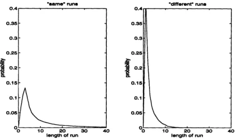
parse the scan-line into runs of Os ("same" runs) and s ("different" runs).
Figure 4-5 shows the 2D run-length distributions for the same set of documents. Clearly, the peaks are much sharper, indicating that there is a higher degree of redundancy in the
images with this model than with one-dimensional run-length coding. Because of this, the
run-lengths will take fewer bits to represent after passing through the entropy coding stage.
Using the difference between adjacent scan-lines is therefore an extremely simple way of
n4r . . .
black run