Publisher’s version / Version de l'éditeur:
Engineering Journal, 44, 3, pp. 79-84, 1961-03
READ THESE TERMS AND CONDITIONS CAREFULLY BEFORE USING THIS WEBSITE. https://nrc-publications.canada.ca/eng/copyright
Vous avez des questions? Nous pouvons vous aider. Pour communiquer directement avec un auteur, consultez la première page de la revue dans laquelle son article a été publié afin de trouver ses coordonnées. Si vous n’arrivez pas à les repérer, communiquez avec nous à [email protected].
Questions? Contact the NRC Publications Archive team at
[email protected]. If you wish to email the authors directly, please see the first page of the publication for their contact information.
NRC Publications Archive
Archives des publications du CNRC
This publication could be one of several versions: author’s original, accepted manuscript or the publisher’s version. / La version de cette publication peut être l’une des suivantes : la version prépublication de l’auteur, la version acceptée du manuscrit ou la version de l’éditeur.
Access and use of this website and the material on it are subject to the Terms and Conditions set forth at
Winter water temperatures and ice prevention by air bubbling
Williams, G. P.
https://publications-cnrc.canada.ca/fra/droits
L’accès à ce site Web et l’utilisation de son contenu sont assujettis aux conditions présentées dans le site
LISEZ CES CONDITIONS ATTENTIVEMENT AVANT D’UTILISER CE SITE WEB.
NRC Publications Record / Notice d'Archives des publications de CNRC:
https://nrc-publications.canada.ca/eng/view/object/?id=e8bb9c2f-5ed5-4d32-85fb-086bced7edb3
https://publications-cnrc.canada.ca/fra/voir/objet/?id=e8bb9c2f-5ed5-4d32-85fb-086bced7edb3
S e r
T H I
N 2 1
1 2
n 0 0
' l
l 7
c o 2
(D
NATIONAL RESEARCH
CANADA
DIVISION OF BUILDING
COUNCIL
RESEARCH
B$lipatiq|&
t p T #
t"4it:,.": t:":i1:qtTA STUDY OF WINTER WATER TEMPERATURES
AND ICE PREVENTION
BY AIR BUBBLINC
by
G. P. Williams
REPRINTED FROM
THE ENGINEERING IOURNAL
voL. 44 NO. 3, MARCH 196I, P. 79-84
TECHNICAL PAPER NO. 117
OF THE
DIVISION OF BUILDING RESEARCH
OTTAWA
MARCH T96T
This publication is being distributed by the Division of Building Research of the National Research Council as a contribution towards better building in Canada. It should not be reproduced in whole or in part, without perrn-ission of the original publisher. The Division would be glad to be of assistance in obtaining such permission.
Publications of the Division of Building Research may be obtained by mailing the appropriate remittance, (a Bank, Express, or Post Office Money Order or a cheque made payable at par in Ottawa, to the Receiver General of Canada, credit National Research Council) to the National Research Council, Ottawa. Stamps are not acceptable.
A coupon system has been introduced to make payments for publications relatively simple. Coupons are available in denominations of 5, 25, and 50 cents, and may be obtained by making a remittance as indicated above. These coupons may be used for the purchase of all National Research Council publications including specifications of the Canadian Government Specifications Board.
Winler Woter Temperolures
ond
lce PreYention
hy Air Bubbling
G. P. WiUia,m,s)
M.E.r.c.
Research Ofticer, Ditsision of Building Research, National Research Council of Canailn, Ottawa il$:$iltliii:i:::::llliii*llil:11.:ii:t:::.'.:: t::ltllliiiil::llitlil::tl::ti:::lil
While
much
information
is available
concerning
the prevention
of
ice formation
by the use
of an air bubbling
system,
apparently
there
has
been
no paper
which
summarizes
this information.
This
report
has
been
prepared
primarily
to be used
by field engineers.
i:itiii:#i:':i'iiiiiiit:tiriiltl.::i''l:::','.: ii::#ill,ll,lli*i*l::.::::l::1.:::' il::it::$t:1itit.*i:::il-lr,l.::1ffi
1rIONSIDERABLE jnterest has
de-U velooed recentlv in Canada in
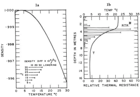
the prerreition iof ice iormation by the use of ail bubbling systems. Although compressed air jets have beerr used to plevent ice formation for many years,r there has been apparently no paper which summarizes completely the information available. This report has therefole been prepared to pre-sent the espre-sential technical informa-tion now available on air bubbling systems. It is designed primarily for field engineers, who are interested in the use of air bubbling systenns but have not yet had an opportunity of investigating their application in de-tail. t . o o o . 9 9 9 l a D E N s t r Y o r F F * , o 3 f c l o 2 0 3 0 L o w E R I N G 3 5 + 30 ---{ 25 ---1 oc 20.'...t 5 -t o &l-t; 5 < ' 9 9 7 . 9 9 6
Fig. la. Density as a function o,I temperature and density difference per degree C lowering for distilled water'
Fig. fb. A tnrical summer temperature profile and associated resistance to mixing.2
o 5 l o 1 5 ? O 2 5 3 0 T E M P E R A T U R E " C
cl R.T.R. = 8 x 10⁻⁵ i.e. the density difference between water at 5'C and 4'C for columns of water 0.5 metres long.
to present some typical observations of water temperatures under winter conditions.
Water Temperatures in Lakes
The temperature of lake water is largely controlled by the process of convectional overturning of water from the surface to the bottom of the lake. The fact that fresh water has its maximum density at 39'2"F affects the circulation and the resulting tem-perature pattern markedly. Fig. la shows density as a function of tem-perature for distilled water as ob-tained from a recent paper by Val,lentyne.2 The density difference per degree centigrade change of perature for water at different tem-peratures is shown in the lower part of Fig. la. Vallentyne stresses that in order to mix fluids physical work must be done and, other factors being constant. that the amount of work is proportional to the density gradient ]n the fluid. As an example he states that "Forty times as much work is required to mix layered water masses at 30' and 29' as the same masses at 5' and 4', because the density dif-ference is approximately forty times greater."
Vallentyne analyz.ed, the tyPical lake temperature profile shown in Fig. lb. He divided the temperature curve into rh metre intervals and, from the dependence of the density on tem-perature, obtained t&re density at the top and bottom of each interval. He defined 'one unit of relative thermal resistance as the resistance to mixing offered by at/z metre column df water with a temperature of 5'C at the toP and 4'C a[ the bottom. BY calculat-ing the density differences between the top and the bottom of. the r/z
> . 9 9 8 F @ z U c!
Air bubbling systems depend on the fact that sub-surface warm water can be brought to the surface by rising air bubbles and thus used to prevent surface ice formation at spe-cific locations. In order to plan an efficient air bubbling system, informa-tion is therefore required on the amount 'of heat available in a water mass. The amount of this thermal reserve can be estimated if water temperatures are known. Information on water temperatures and the factors which affeet them are not generally available to Canadian engineers, so that it is a further purpose of this report to outline briefly the factors which govern water temperature, and
^ o V E lb TEMP "C 5 r o 1 5 2 0 ? 5 3 0 3 5 0 r 0 2 0 5 0 4 0 s 0 6 0 7 0 R E L A T I V E T H E R M A L R E S I S T A N C E 4 6 lrj E F 6 lrl E z 8
E r o
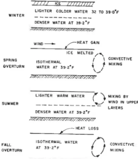
o-U o t 2 l 4 t 6ffi/ , t / / t c L / / / / / / / / / 7 L I G H T E R C O L O E R W A T E R 3? TO 59,0'F W I N T E R D E N S E F W A T E R A T 3 9 2'F wtND + /-BEAI GAIN t c E M E L T E D / , \ S P R l t G t s o T H E R M A L / l c o f f v E c r l v E 9 V E R T U R N W A T E R A r 3 9 2 . F { | v t x t l c 2ZVV:<VpN;W7TZ L T G H T E R w a R M w A r E R f \ u r x n c a v S U T M E R - . E / - _ W I f l D I N U P P E R L A Y E R S O E N S E R W A T E S A T 5 9 2 ' F W/NWpNZSzpNv - H E A T L O S S
:i:.",,""
11"T"::::'**^
p ;:llT',*
Fig. -2.^ Annugl temperature cycle illus-kated for a deep lake in the iemperate
metre intervals and comparing them with the standard, he then catrculated for each interval the relative thermal resistance to mixing. The results of his calculations are shown in Fig. lb. It may be seen that a slight increase in temperature difference in the warm water at the surface results in a large increase in the resistance to mixing. Fig. 2 illustrates annual tempera-ture changes in a typical deep lake. The water temperature of lakes is so markedly influenced by the process of convective heat transfer that it has been used as a basis of classification for fresh water lakes. Horton3 divided lakes into three basic types:
(i) Uglar - surface temperature always below 39.2'F
(ii) temperate-surface tempera-ture alternating above and below 39.2'F
( i i i ) tropical-n e ve r be I o w 39.2'F.
He further divided the lakes into three classes according to depth: the first order 200 ft. and greater, second order 25 to 200 ft. and the third order 25 ft. and less.
In Canada most lakes of interest can be olassed as temperate. In this type, with a first order lake, there are usually two turnover periods, in the spring and fall (Fig. 2). A second order lake, of depth 25 to 200 ft., also has two rnarked overturn periods in the fall and spring, but often in the summer there is cromplete mixing to the bottom, and in the winter the water on the bottom of the lake can cool below 39.2'F. A third ,order or shallow lake will have cornplete circulation at all seasons except wben the surface is frozen. Brewera indi-cates that water in a shallow lake at Barrow, Alaska, was essentially
iso-thermal at any time during the ice free period. Fig. 3 illustrates the convective mixing ,of a shallow body of water during a period of cooling. Tlhese measurements made by thi author illustrate that water remains essentially isothermal as long as the surface temperature is above 4.0'C
(3e.2'F).
Although water in third order lakes
surface and bottom water is so great that the wind is unable to induce complete mixing, even though the lake is only three metres deep. The density difference is caused by large amounts of dissolved Epsom salts.
The importance of depth in study-ing the thermal regime of lakes can-not be overemphasized. Lebedev5 states that "In the majority of cases the range of the lake heat budget is determined by the mean depthr'. In Sweden Mehne made some tempera-ture measurements on Lake Kallsjiin, which consists of three separate basins of different depths, coniected by narrow shallow puisager. He con-cluded that in thermal respects eaah basin could be classified as a separate lake. The shallow basin warmed more rapidly in the spring and cooled more rapidly in the fall, and the water temperature reaahed higher tempera-tures in the summer than in the other basins at corresponding depths.
In a Iake considerable mixing can be caused by wind action. BrettT
water to the surface. He also suggests
A 4 0
E. U b U3
a n r " ' F L u I O O o 1 2 0Iig. 3: Temperatu,re _variations in shallow pool of water subject to cooling condi-tions. Feb. 17, 1959, Ottawa.
o . 5 r . o r . 5 2 . o
T E M P E R A T U R E Fig. 4. Variations of water temperature with depth in the northernmost part of Lake Kallsjon, Sweden in March 1939 to 1945. Lowest water temperature ob-served during warm winter. Winter temperature of water in deep lakes is dependent on factors other than winter air temperature.ro
that in treezing weather an air hole can be made larger by wind circula-tion, as the edge of the ice melts when warmer water is brought to the surface by wind action.
One major factor in determining water temperature is the heat flowing into or out of a specified area because of different water currents. Rauson0 in a study of water temperatures in Great Slave Lake indicates the varia-tion in water temperatures that can be caused by inflow from a large river.
It is not always appreciated that the winter water temperature of a
Iake shows considerable variation
when observations are taken at the same time in different years. Fig. 4 shows the variation of water
tempera-ture with depth in lake Kallsjrin,
Sweden, for different years. Melin 10 noted that the mean winter tempera-ture of lake water did not necessarily depend on the mean air temperature. According to his report the coldest
W A T E R T E M P E R A T U R E ( " C ) o " + l + z + 3 l r l l + 4 + 5 + 6
r t l
+ 7 + 8 + 9 + l O + i l + t 2 + 1 3l l t t r l l6
UJ ! (t 2 lr, o lr E, f o=
o G,u
-F G lrl cto
2 4 6 8 t o-\
t I l _ I t\
\
0 8 3 0 H R a v - l r r u c x o r T O M OF TANK 9 3 o l 7 3 o | 5 3 o H R I H R I N Nwater temperatures were observed during a comparatively warm winter.
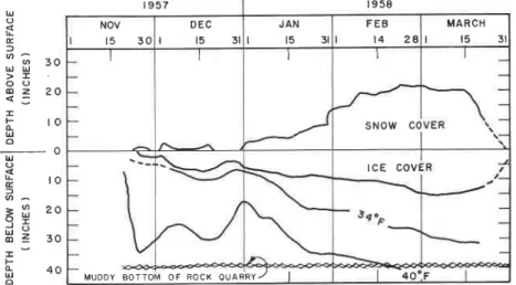
Fig. 5 illustrates the gradual water' temperature changes underneath the ice covel of a small pond in the Ottawa area measured by the author during 1957-58. At this particular site, the water at the bottom of the pond did not reach its maximum
density until mid-February, although
it should be noted that in late De-cember a mild spell reduced the thick-ness of ice cover and appeared to increase the water temperature ap-preciably.
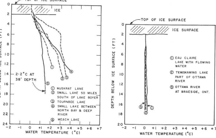
Fig. 6 shows some water
tempera-ture profiles under ice covers in
small lakes obtained by the author in the Ottawa area. These are more typical of conditions in this region and may be compared with water temperature profiles taken in several lakes in north Sweden by Melin.lo The lakes in the Ottawa area may be classed as third order or shallow lakes, whereas the lakes in Sweden may be classed as second order lakes. River Water Temperatures
In rivers the water mass is kept at nearly the same temperature by
mix-ing. Thus an ice cover will not start to form until the temperature of the whole mass of river water is close to 32'F. Fig. 7 shows some tlpical water
temperature profiles taken by the
author in the Ottawa area in March, 1959. Even in Lake Temiskaming, a wide part of the Ottawa river where the flow velocities must be very low, there was sufficient mixing to prevent an appreciable temperature gradient
from develroping.
It is obvious that in rivers the heat inflow from upstream sources must have an important effect on the water temperatures at a particular site. For example, Cousineaull states that the water temperature at a particular sec-tion of Bersimis River never dropped to freezing point although this river is subject to fairly extreme winter cooling conditions. U o f
3 f r 3 0
> -o -o @ z ? O < : Ih
r o
U o - o U o E , -l @ ^ = l ? ? o 6 z 3 0-c a 6 u ' -o
Fig. 5. Temperature variations under small ice covered pond - NRC grounds, Ottawa.
TABLE T
Surnrnary of Air Bubbling Systerns Reported in the Literature
PInce
Size of Spacing of Slze ot
Hol.e- HoIe Line
Size of Depth to
Cornpressor Boltont General
| 9 5 7 t 9 5 8 NOV D E C t t 5 3 J A N l 1 5 3 l F E B l 4 2 A M A R C H t t 5 3 l s N o w cc M U O D Y B O T T O t c E c o v l o F R o c K o u A R R Y - / | 4 o " . F Lake Miilaren Sweden 0.75 mm 10 metres l l l i n . I . D . 1 . 5 m 3 / m i n . a t , anchored at 4 atmospheres 1-2 m from bottom 10-15 Reference #14
metres approx. 900 metres
length of area eleared of ice Riddar Bay, Sweden 0.75 mm 50 mm I.D. and 22 mm I.D. 8m3/min. D - / . O metres 5-20
metres variable successReference # 14, Prescott,
Ontario
l/32 in. 6-ft.
intervals I ft. from bottom3/4 in. anchored at 15-ft. centres alr pressure 40 p.s.i. 5-11 fr. Reference # 19 Celgar Ltd. B.C. 40-fr.
intervals 2O0O' of fu ilr.600' 1-1.5 in.
125 c.f. per mtn.
I/32 in. 15-20 ft. Reference #20,
2-acre pond free of ice
Vernon Lake Narrows, Ont. 1/16 in. 1O-ft. intervals 1.5 in. across 800-ft. channel Reference #21, 200-ft. strip kept open Kaministiquia River, Ft. William, Ont.' I%-llh in., 2000 ft. anchored 1 ft. from bottom Reference #12, open water approx.
400 ft. x 15 ft. throughout winter Slave Falls,
Manitoba
1.5 in. iron pipe at 14 ft. along
1200-ft. dam
Reference # 12
Mid-Finland District,
Finland 0.8 mm metres3-3.5 |l-in. steel pipealso fu irl^.
plastic hose compressors at both banks of river Reference #22, area 15 metres by 15 metres opened
Finland Norn: A 170-metre channel with an ice cover 60-70 cm
thick required 43 compressorfiours and 7! man
hours to'melt. Reference #23
0.75 in. 3.5 metres 50 ft. Reference #24 200 c.f. per mln. l-lft steel pipe 1000 ft. Safe Harbour, Maine
Sea-Water Temperatures
Although air bubbling systems have been used in sea water,12 careful studies must be made of water tem-perature and salinity to ensure that ice can be removed or melted bv this technique. The maximum density of sea water does nrot occur at 39.2"F and, therefore, convective mixing of the water may continue until ice forms at the surface. For air bubblins to be successful under these condil tions, it is necessary that the water brought to the surface by the bubbles should have a salinity and tempera-ture such that heat can be released for melting ror preventing ice 'forma-tion, that is the temperature of the salt water is higher than its fteezing temperature. The fireezing point oT salt water decreases with increasing salt content. The action of wind and water currents is likely very import-ant in detertnining water temiera-ture profiles at a specific location. Fig. 8 shows the temperature gradi-ents Tadashils found under an ice oover in sea water.
No mention has been made of the subsurface flow resulting from varia-tions in the amount of materials in suspension or horizontal variations in the amount of salt in sea water. The subsurface flows which result from these density differences are often referred to as "density currents" in engineering literature. For example,
the upstream movement of salt water in open channels is attributed to the greater density of salt water com-pared with that ,of fresh water. The nature of such an intrusion is depend-ent upon the range of the tide and salinity of the sea water and the physical and hydraulic characteristics of the site. The effect of such intru-sions are important in analyzing the thermal regime at those sites where salt water is mixing with fresh water or water of different salinity. Design Considerations for Air Bubbling Systems
In any careful study of the feasi-bility of using an air bubbling tech-nique to prevent ice formation, a thorough field investigation of the thermal regime of the particular site in question is an absolute necessity. An understanding of the heat losses to be expected from the surface and the lateral inflow of heat are also usually essential. In Swedenla a case was reported where an area 50 metres by 1.5 metres was kept free of ice when the mean water depth was only one to two metres. Converselv an-other instance was reported in the North Baltic where an installation in quite deep water was a failure be-cause -of supercooled water flowing into the area from a river source.
In the case of an open body of water under winter conditions, there
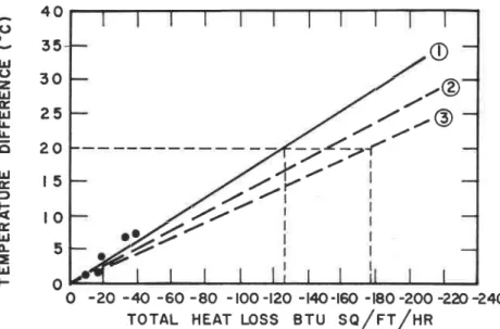
can be very large heat losses from the surface. Fig 9 compares varjous empilical formulaeu' 16 1? which give estirnated heat losses for various air-water surface temperature differences. From these formulae it can be esti-mated that for a mean air-water sur-face temperature difference of 20'C (36'F), the total heat losses from an open water surface would be ap-proximately 725 to 175 B.t.u. per sq. ft./hr.
Once an ice cover has formed, the rate of heat loss will be rapidly re-duced because of the insulatine value of the ice cover. For examplJ, with an ice cover of 6 in. and a temoera-ture gradient through it of 1.5'Flin., the heat loss is approximately 22 B.t.u./sq. tt./hr. It the ice cover is removed by air bubbling and the air-water surface temperature difference is approximately 20"C (36'F), then the heat lross would be L25 to 175 B.t.u. per sq. ft./hr.
If, for this example, the depth of the water was 20 ft. and the mean water temperature *33'F, then the thermal reserve would be 1250 B.t.u./sq.ft. of open water area. If the rate of heat loss rvas 125 B.t.u./sq.ft./hr. and no ice cover existed, the mass of the water would be cooled to 32'F within l0 hours. In the case where there is an ice cover and part of the ice is removed by air bubbling, the heat in the water Fig. 6. Typical water temperature profiles under ice cover
for small lakes in Ottawa area Mar-ch 9-ll. i0t-9.
2
//72' ,",
2 . 2 " c A T 3 8 . D E P T H @ v u s x R n r L a u e @ s r r , l a u l L A K E 5 0 M t L E s S O U T H O F L A K E B O Y E R @ r o u n n e e e l a x e @ s u n u l L A K E B E T w E E N N O R T H B A Y A O E E P R I V E R O M E A C H L A K E;
u _ b ; 8 E = t O at lrj < > 1 2=
o 1 4 J trj dl t 6 I F (L trJ 18 o - l O + l + 2 + 3 + 4 + 5 + 6 W A T E R T E M P E R A T U R E ( " C )Fig. 7. Typical water temperature variation under ice sheet in flowing rivers,_ _Qqa*a area, March lg5g, (Temp.
gradient less than 0.1.C l0
feet.)-/ . - T O P O F I C E S U R F A C E
2
%
r c E suRFAcE
O E A U c L A T R E L A K E W I T H F L O W I N G W A T E R @ r e u t s r a u r H G L A K E P A R T OF OTTAWA R I V E R @ o r T A w a R r v E R A T B R A E S I O E , O N T . o + l + 2 + 3 + 4 + 5 + 6 W A T E R T E M P E R A T U R E ( . C );
L 4
;
o o E f 8 U' UJ o l O b 1 2 J lrJ r D A Fft 16
o l 8 2 0? z
2 4- 2 2 0 + 7 - 2 - l + 7S E A W A T E R T E M P E R A T U R E - 3 - 2 - t O + l
r t t t l
for some distance surrounding the open area is available by advection for maintaining the water in the open area above 0'C.
Additironal heat that can be sup-plied from the bottom of a lake or river is usually considered a minor factor. Nybrantls states that in lati-tude 50 to 60'N, the heat flow from the typical bottorn material in Octo-ber is apprroximately 1.8 B.t.u./sq. ft./hr; in December-January 1 to 1.8 B.t.u./sq. ft.,/hr, decreasing to almost negligible flow in April.
To plan the spacing and depth of air holes in a bubble system, informa-tion is required on the area of influ-ence of a single air iet, 'on the size of air hole, and on the most efficient quantity of air to use. Since most studies on air bubbling systems ap-pear to have been empirical, designed to give an answer for a specific loca-tion, there does not appear to be an engineering procedure for obtaining this design information. A summary of the various applications is outlined on Table I which gives the design values that have been reported in the literature. Although this table does not present a means of determining such things as air hole spacing, it does list the values which apparently have been satisfactory for the specific locations listed. In addition to the
S A L I N I T Y (% ) 3 f 3 2 3 3 3 4
l l t l
list of studies shown in Table I, there are a number of other cases reported where the technical information is so meagre as not to warrant inclusion in this table.
Experimental Investigations
Although most of the studies re-ported were empirical, there have been several experimental investiga-tions on air bubbling techniques. Owen25 in 1942 reported a detailed investigation of the flow pattern of various orifices studied in the de-velopment of an orifice to use For ice orevention at the Grand Coulee Dam. An orifice was developed which gave a balance between flow pattern, eco-nomy of operation, and non-freezing characteristics of the orifice.
One of the few other experiments in the laboratory on the flow of water induced by a rising column rof air bubbles was recently completed by Baines and Hamilton.26 They con. cluded that because the momentum of the vertical jet increases with dis-tance from the source, other factors being equal, air bubbles increase in efficiency with depth. They indicated that the ratio of water discharge to air discharge increases with depth, but decreases with increasing air dis-chalge. They also concluded that, with single orifices of 0.02 in. size or
larger, flow is independent of size of orifice and depends only ron the air discharge. They reported, 'finally, that further experiments might indi-cate that it is possible to apply scal-ing laws and thus have reliable model tests of air bubbling systems.
Clinch, Millman, Erickson2? at-tempted to obtain some quantitative information on air bubbling systems under field conditions. Their calcu-lated air-water flow ratios for a par-ticular site varied over a wide range, but this they attributed to the inade-quacy of field observations.
The area of influence of one air jet and the resulting water tempera-ture distribution during air bubbling operation is a basic question which has not been answered satisfactorily. The only quantitative measurements on this problem of which the author is aware were made by Nybrant.2E He noted that essentially the same water temperature was maintained throughout the whole body of water as far as 50 metres from the h,ose. He also noted that there did not seem to be a decrease in water temperature above the hose. as the mean tem-perature of the adjacent water was about the same. These observations suggest that, for this one applicati,on, the air bubbling system obtains very complete mixing of water within 50 metres of the hose. Although this one example is not sufficient to lead to a definite conclusion, it does suggest that the spacing of holes might be larger than is commonly used, as shown in Table I. In the Malar in-vestigationsla it was found that chang-ing the spacchang-ing of the holes from 5 to l0 metres did not seem to change the area kept free from ice formation,
In what is perhaps the most de-tailed'field investigation of air bubbles systems, Kaitera2e made many obser-vations of water temperature during air bubbling trials. He noticed that the temperature of the water did not fall as low as would be expected above the hose, though considerable heat was used to melt the ice and keep the area free of ice. He suggests that there must be considerable lateral movement of heat into the area near the air hose from the adioining water mass.
Kaitera also investigated the de-pendence of ice melted on the volume of the compressed air used, the tem-perature of the water and the depth of bhe nozzle. Fig. l0 summarizes his findings. As might be expected, the higher the water temperature and the greater the depth of nozzle, the better the ice melting rate. His experiments provide some useful information on actual quantities of ice that can be
("c )
+ ?I
3 5I
30 I J- 6 0
tt) IrJ E 8 0 F t!3 r o o
r
F 2 0 o-lrl o 4 0 2 0 4 0 8 0 2 0 0 A T 4 O O M E T R E S S A L I N I T Y A T 4 O O M E T R E S = 3 3 ' 6 ? " h F R E E Z I N G P T . = - 1 . 8 3 " CFig. 8. Sea water temperature and salinity profiles at time of ice formation and under ice cover.l3
6 0
s H A L L o w
w A r E R ( . r o r r o * |
p R o F t L E W A T E R i'*-lY'-..wj\rER
P R O F I L E T E M P = - 0 . 2 9 " cmelted under field conditions. Conclusion
It is possible that much of the in-formation available on air bubbling systems has not been made public. Judgur-g from the reports that are available, however, considerable in-vestigation is sti'll needed before this technique can be so developed as to be the most efficient way of using the heat stored in water under ice cover to prevent ice formation. Aclcnowledgements
This paper is a contribution of the Division of Building Research of the National Research Council of Can-ada, and is published with the ap-proval of the Director of the Division. The author is indebted to several members Of the Division, particularly to Mr. L. Gold, for helpful criticism of this report, and to Mr. R. Armour for help with some of the temperature measurements.
References
l. Skerrett, R. G. Reducing fce Pressures
wilh Compessed Air.-Canadian
En-gineer, Vol. 45. 7923, pp. 181-185.
2. Vallentyne, J. R. Principles of Modern
Ljrnlology. American Scientist, Vol.
45, No. 3, June 1957, pp. 278-244.
3. Horton, R. E. General Report on
Lim-nology. fnternational Union of
Geo-desy and Geophysics, International
Association of Scientific Hydrology.
1939.
4. Brewer, Max C. The Thermal Recime
of an Arctic Lake. Amer.
Geopf,ysi-cal Union, Transacilons, Vol. 99, No.
2. April 1958, pp. 278-284.
5. Lebedgv, V. N. The Probletn of
Quan-lilalive Delermination of
Tembera-lure Condilions in Fresh Water Ilakes
wilh neference lo lhe Factots
Al-leclLrg It. International Union of
Geodesy and Geophysics,
Interna-tional Association of Scientific
Hy-drology. 1939.
o
t
- t @
./ -(o
?{' - @
!.
I. _ - / _
7
/-'//'
'./.2//'
.(J c lrJ o 2 lrl E ul l!5
o
lrl G, f F {L E UJc
=
lrl4 0
3 5
3 0
2 5
2 0
l 5
! o
5
o
o -20 -zto -60 -80 -too -t20 -t40-t@ -t80 -200 -2n-2.40
T O T A L H E A T L O S S B T U S A /N / N A
/ /
Fig. L Various empirical forrnulae for estimating total heat loss from open water
sq;fgggs15,16,1r.
o observations on heat losses from small lake in lg59 by G. P. Williams.
zr. a*P"Iil're53.9;11 warer work
Fig. 10. Dependence of melted ice on depth oI nozzle under various conditionszg. *10.'ln,Bl"inTti*iri'ecord' vol'
6. Melin, Raqnar. TetnDeralure
ObEetva-tions in Bwedish Likes, International
Union of Geodesy and Geophysics,
International Association of
Scien-tific Hydrology. 1939.
7. Brett, J. R. The Pbysical Limnology of
Lakelge Lake, B.C. Journal of
Fish-eries Research Board of Canada.
Sept. 20, 1949, pp. 82-102.
8. I(uenen, P. H. Realtns of Waler, p. 245.
Cleaver-Hu.me Press Ltd.. London.
1955.
9. Rauson, D. S. The Physical LimnoloEy
ol Greal Slave Lake. Journal of
Fisheries Research Board of Canada.
Vol. 3. 1950-52. pp. l-66.
10. Melin, Ragnar. Invesligalions al the
Meleorological and Hydrological
In-slilule of Sweden Concerning the lce
Condllions on Lakes and nivers.
Swedish Hydro Met. Inst.,
Communi-cation Series No. 1. 19,W.
11. Cousineau, J. E. Some Aspects of Ice
Problems Connecled wilh
Hydro-Elecldc Developmenls. Proceedings,
Eastern Snow Conference. 1959.
12. Temperalure Fallg Bubbleg Rise, Ice
Mells. Compressed Air Comments.
Atlas Copco, Vo]. 2, No. 1. Feb. 1959.
13. Tadashi, T. On lbe Formation and
Growlh ol Sea lce, Especially on the
Okholsk Sea. Proceedings of
Confer-ence on Arctic Sea Ice., Nat. Acad.
of scienee, u.s. NRC Publ. 598. Feb. 1958. pp. 169-180.
14. Holm, A. Plaslic TuJoing and
Com-pressed Air WiU Provide Walerways
Free from lce-Plastverlden hr 4.
1957.
15. Wemelsfelder. P. J. The Inllrence of
an Ice Cover on llte Dischuge
Con-dilions of a River. International
Union of Geodesy and Geophysics,
International Association of
Scien-tific Hydrology. 1954. pp. 182-190.
16. St. Lawrence Walerway Proiecl,
ne-porl ol toinl Board of Englneers.
Ice Formation in the St. Lawrence
and Other Rivers, Appendix E.
(1924). p. 40S.
17. Wardlaw, R. L. A Sludy of Heat Losses
from a Waler Surface as nelated lo
Winler Navigation Proceedings,
Eastern Sno\/ Conferenee. Vol. 2.
1953 and 54,
18. Nybrant, G. Water Tenrperalure in
Winler in a Pond md ils Dependence
upon Flow. Seminar, Ice Problems in
Hydraulic Structures. 8th Congress
fnt. Assn. .tor Hydraulic Research,
r959.
19. Private Communication.
20. Bubbles Eliminale lce from Loq Ponds,
Timber of Canada, Vol. 18, No. 4.
22. Translation of article The OpenirrE ol
Ferry Chamels Using the
Cbm-pressed 5'ir Melhod. I. Alanko.
(Pri-vate Communication.)
23. I{inch, K. Winter noad Conference in
Finland, Svenska Vegforening Ted.
Vol. 40. April 1953. pp. 111, 112.
24. Granbois, Kenneth J. Experimental
Use oI Air Bubbles for the Control
of Sheel lce al SaIe Harbof.
pro-ceedings Eastern Snow Conference,
Vol. 2. 1953-54.
25. Owen, T. G. Ice Prevention by fhe
Air-Lift Syslem al Grmd Coulee.
Trals- A.S.M.E. vol. 64. t9rt2. pp.
2.Ot-206.
26. Baines, W. D. and G. F. Harnilton. On
lh€ Flow of Water Induced by a
Rising Colum! of Air Bubbles. Int.
A-ss,n. for Hydraulic Research. Aug.
1 0 E O
27. Clinch, n. L., R. N. Millman and O. M.
Erickson. Ice Problems at lilcCormick
Dam. Seminar, Ice Pxoblems in
Hv-draulic Structures. 8th Congress ltit,
Assn. for Hydraulic Reseaich. 1959.
28. Nyilrant, G. Investigallon! orr the
Waler Tenperalure-al A'ir Bubbles
Syslems in La&er. Seminar, Ice
prob-lems in Hydraulic Structures. 8th
Congress Int. Assn. for Hydraulic
Research. 1959.
29. Kaitera, P. Keeping Waler from
Freez-tnS by Means of Compresa€d Air.
International Union of Geodesy and
Geophysics, International
Astocia-tion of Scientific llydrology. I948.
pp. 3e0-3e8. U al 160,