HAL Id: hal-02112282
https://hal.inria.fr/hal-02112282
Submitted on 26 Apr 2019
HAL is a multi-disciplinary open access
archive for the deposit and dissemination of
sci-entific research documents, whether they are
pub-lished or not. The documents may come from
teaching and research institutions in France or
L’archive ouverte pluridisciplinaire HAL, est
destinée au dépôt et à la diffusion de documents
scientifiques de niveau recherche, publiés ou non,
émanant des établissements d’enseignement et de
recherche français ou étrangers, des laboratoires
Programmable Networks
Andrea Tomassilli, Giuseppe Di Lena, Frédéric Giroire, Issam Tahiri, Damien
Saucez, Stéphane Perennes, Thierry Turletti, Ruslan Sadykov, François
Vanderbeck, Chidung Lac
To cite this version:
Andrea Tomassilli, Giuseppe Di Lena, Frédéric Giroire, Issam Tahiri, Damien Saucez, et al..
Bandwidth-optimal Failure Recovery Scheme for Robust Programmable Networks. [Research Report]
INRIA Sophia Antipolis - I3S. 2019. �hal-02112282�
0249-6399 ISRN INRIA/RR--9272--FR+ENG
RESEARCH
REPORT
N° 9272
April 2019Project-Teams Coati and Diana
Bandwidth-optimal
Failure Recovery Scheme
for Robust
Programmable Networks
A. Tomassilli , G. Di Lena , F. Giroire , I. Tahiri , D. Saucez , S.
Perennes , T. Turletti , R. Sadykov , F. Vanderbeck , C. Lac
RESEARCH CENTRE
SOPHIA ANTIPOLIS – MÉDITERRANÉE
2004 route des Lucioles - BP 93
A. Tomassilli
∗, G. Di Lena
† ‡, F. Giroire
∗, I. Tahiri §, D.
Saucez
†, S. Perennes
∗, T. Turletti
†, R. Sadykov §, F.
Vanderbeck §, C. Lac
‡Project-Teams Coati and Diana and RealOpt Research Report n° 9272 — April 2019 — 21 pages
Abstract: ISP networks are taking a leap forward thanks to emerging technologies such as Soft-ware Defined Networking (SDN) and Network Function Virtualization (NFV). Efficient algorithms considered too hard to be put in practice on legacy networks now have a second chance to be considered again. In this context, we rethink the ISP network dimensioning problem with protec-tion against Shared Risk Link Group (SLRG) failures. In this paper, we consider a path-based protection scheme with a global rerouting strategy, in which, for each failure situation, we may have a new routing of all the demands. Our optimization task is to minimize the needed amount of bandwidth. After discussing the hardness of the problem, we develop two scalable mathematical models that we handle using both Column Generation and Benders Decomposition techniques. Through extensive simulations on real-world IP network topologies and on random generated in-stances, we show the effectiveness of our methods. Finally, our implementation in OpenDaylight demonstrates the feasibility of the approach and its evaluation with Mininet shows that technical implementation choices may have a dramatic impact on the time needed to reestablish the flows after a failure takes place.
Key-words: Software Defined Networking, Network Function Virtualization, network resilience strategies
∗Université Côte d’Azur, CNRS, Inria Sophia Antipolis, France †Inria, Sophia Antipolis, France
‡Orange Labs, France
Contents
1 Introduction 4
2 Related Work 5
3 Problem Statement and Notations 5
4 Optimization Approaches 6
4.1 A layered network model . . . 7
4.2 Compact ILP Formulation . . . 7
4.3 A Column Generation Approach . . . 8
4.4 Benders Decomposition Approach . . . 10
4.5 The Min-Overflow problem . . . 10
5 Numerical Results 13 6 Experimental evaluation 16 6.1 Implementation options . . . 16 6.2 Experimental setup . . . 18 6.3 Recovery time . . . 18 6.4 Operational trade-offs . . . 19 7 Conclusion 19
1 Introduction
Network failures such as cable cuts, natural disasters, faulty interfaces, and human errors arise as part of ISP’s everyday operations [1]. Clearly, they need to be taken into account when allo-cating resources to the network. Faults in the IP and optical layer tend to be correlated between them [2]. Indeed, the failure of a component located on a common router, such as a linecard, or in the underlying optical infrastructure, such as a common fiber, may result in the consequential failure of multiple entities at the IP layer. To model this correlation, Shared Risk Link Groups (SRLGs) have been introduced [3]. SRLGs allow to easily express a risk relationship, and also, they can represent different types of failures, such as single and multiple, nodes and links failures. We consider in this paper a protection technique called unrestricted flow reconfiguration, also known as global rerouting [4]. In each of the possible failure situations, a new set of backup paths are defined, one for each demand. This makes this protection method bandwidth-optimal. However, this also means that each failure may result in a completely different routing for the demands. In legacy networks, it is impractical to implement this technique due to the large number of rules to install on the network devices and hence signaling overhead. However, the introduction of SDN may change the game.
With SDN the network control is decoupled from the packet forwarding data plane. Network in-telligence is centralized in the controller that maintains a global view of the network [5]. Routing decisions are taken in a single location, the controller, with a complete knowledge of the network state instead of resulting from a distributed algorithm. As a result, with SDN, the global rerout-ing protection schema may be put in practice.
We address in this paper the problem of designing an SDN programmable network with NFV Infrastructure (NFVI)-enabled servers that provides SRLG-failure survivability under the global rerouting protection schema.
Our goal is to compute for each demand, a primary and a backup path for each SRLG failure scenario, while ensuring that the required network functions will be performed on the packets in the order specified by its Service Function Chain.
The studied problem is a dimensioning problem for an ISP which has to understand the amount of resources which need to be deployed in the network and want to minimize resource usage, while guaranteeing protection against an SRLG failure. Even though, at first glance, the problem may appear easy due to the absence of capacities constraints, we demonstrate that it is not the case. Indeed, we show that even for a single demand the problem is NP-Hard and inapproximable within (1 ✏) ln(|R|) for any ✏ > 0 unless P=NP, where |R| denotes the number of SRLG failure scenarios.
Our contributions can be summarized as follows.
– To the best of our knowledge, we are the first to provide a scalable exact method to solve the problem of global rerouting in SDN/NFV-enabled networks with SRLG constraints.
– We also propose a fast 2-phase polynomial method. The first phase consists in solving the fractional relaxation of the problem. The second one is building an integral solution from the fractional one. It leads to an optimization problem we named Min Overflow Problem. We show that the problem is NP-complete, but that there exists a (1 + 1
e+ ")–approximation
algorithm to solve it.
– We demonstrate the applicability of our proposed protection method in Mininet and study metrics such as the burden on the network elements and time to recovery from a failure. We also discuss the technical choices to be taken into account by the network operator in order to put in practice our proposed technique.
The rest of this paper is organized as follows. In Section 2, we discuss related work. In Section 3, we formally define the problem to be studied, as well as notations that will be used in
this paper. Section 4 develops the proposed optimization approaches. In Section 5, we validate our models by various numerical results on real world and randomly generated data instances, and in Section 6, we use Mininet to demonstrate the feasibility of our proposal. Finally, we draw our conclusions in Section 7.
2 Related Work
The problem of providing network protection against failures has been widely investigated in the last decades, see, e.g., [6]. With the advent of SDN/NFV, there are more opportunities to create, deploy, and manage networks more efficiently. Indeed, with SDN and its control–data planes decoupling, routing decisions can be done using a logically centralized approach. This paves the way for a broadening of perspective in terms of fault management [7].
Chu et al. [8] consider a hybrid SDN network and propose a method to design the network in such a way that fast failure recovery from any single link failure is achieved. Their proposal consists in redirecting the traffic on the failed link from the routers to SDN switches through pre-configured IP tunnels. Next hops are pre-configured before the failures take place, and the set of candidate recovery paths for different affected destinations is chosen by the SDN controller in such a way that the maximal link utilization after redirecting the recovery traffic through these paths is minimized.
Suchara et al. [9] propose a joint architecture for both failure recovery and traffic engineering. Their architecture uses multiple pre-configured paths between each pair of edge routers. In the event of a failure, the failover is made on the least congested path that ensures connectiv-ity. Besides, Sgambelluri et al. [10] propose a controller–based fault recovery solution that uses OpenFlow’s Fast Failover Group Tables to quickly select a pre-configured backup path in case of link-failure.
Different from previous studies on failure recovery, we present a simple and bandwidth-optimal approach based on multiple backup paths to protect the network against SRLG failures where SDN switches are deployed. We previously introduced the concept in [11].
The idea of using a set of pre-configured multiple backup network configurations is not new. For instance, in [12, 13] the authors propose a pre-configured proactive IP recovery schema that makes use of multiple routing backup configurations as a method for fast recovery. The main idea is to create a small set of backup routing configurations to be used in the case of a single link or node failure. Since the backup configurations are kept in the routers, it is necessary to reduce their number in order not to require the routers to store a significant amount of state information.
Herein, we take to the extreme the idea of multiple routing configurations by allowing a com-pletely different routing in response to an SRLG failure situation. Different from the above works, our aim is to provide a bandwidth-optimal mechanism to design a reliable network. Be-sides guaranteeing the recovery, our proposed approach also takes into consideration the SFC requirement of the flows.
3 Problem Statement and Notations
We model the network as an undirected graph G = (V, E), where V represents the set of nodes and E the set of links. We are given a set of SRLG eventsR that can incur link failures. Each r 2 R consists of a set of links that share a common physical resource. We denote by D the set of demands. As we are solving a dimensioning problem, we assume prior full knowledge of traffic demands, i.e., traffic matrices are known beforehand. A demand d 2 D is modeled by
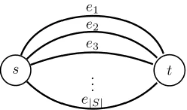
s ... t e1 e2 e3 e|S|
Figure 1: The multigraph resulting from the reduction
a quadruple (sd, td, bwd, Cd) with sd the source, td the destination, Cd the ordered sequence of
network functions that need to be performed to all the packets belonging to the flow of the demand, and bwd the required units of bandwidth. We denote by `(d) the length of the SFC for
a demand d.
Network functions need to be executed on the so called NFVI nodes. Not all the nodes are enabled to run virtual functions. We denote by Vvnf✓ V the set of VNF-enabled nodes.
Moreover, we assume that an NFVI-enabled node can only run a subset of the network functions, as there may be constraints on their location in the network (e.g., geography or regulatory constraints and anti-affinity rules).
Given the network topology and the traffic rate of the demands to be supported, the purpose of the design problem is to precompute a set of paths to guarantee the recovery of all the demands in the event of an SRLG failure, while satisfying their SFC requirements. The considered optimization task is to minimize the required bandwidth in the network. We refer to this problem as the Global Rerouting problem.
4 Optimization Approaches
We begin the section by proving hardness and inapproximability results for the Global Rerout-ing problem. Then, we propose a scalable decomposition model which relies on the Column Generation technique which is based on a layered network model.
Proposition 1. The Global Rerouting problem is NP-hard even for a single demand, and cannot be approximated within
(1 ✏) ln(|R|) for any ✏ > 0 unless P=NP, where |R| denotes the number of failing scenarios. We use a reduction from the Hitting Set Problem, which is defined as follows. We are given a collection C of subsets of a finite set S and the problem consists in finding a hitting set for C, i.e., a subset S0 ✓ S such that S0 contains at least one element from each subset in C of
minimum cardinality. Given an instance I = (S, C) of Hitting Set, we can build an instance I0 = (G,D,R)of Global Rerouting in the following way. G = (V, E) is a multigraph with
V ={s, t} and E = {ei, i = 1, ...,|S|}. All the edges have s and t as endpoints. See Fig 1 for an
example. For each C0✓ C, we add a failing scenario r
C0 = E\ C0 to R, corresponding to edges
that cannot be used in the failure situation r. Finally, we add to D, a demand d with s and t as source and destination respectively, and with charge equal to 1. The goal now consists in finding a path for each of the failure scenarios r 2R minimizing the needed capacity to deploy. The total capacity needed to satisfy d in each of the failure situations does not exceed c () there exists a hitting set of cardinality not greater than c. The proposition follows immediately from the fact that Hitting Set is NP-Hard [14] and cannot be approximated within a factor of ln|S| [15], unless P=NP.
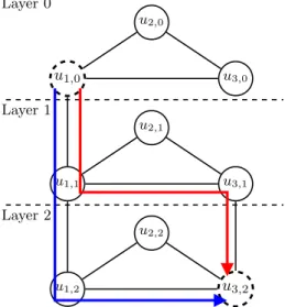
Layer 0 u1,0 u2,0 u3,0 Layer 1 u1,1 u2,1 u3,1 Layer 2 u1,2 u2,2 u3,2
Figure 2: The layered network GL(d)associated with a demand d such that s
d = u1, td = u3,
and Cd= f1, f2, with G = (V, E) being a triangle network. We assume f1 installed on Node u1
and f2 installed on Nodes u1and u3. Source and destination nodes of GL(d) are u1,0 and u3,2,
respectively. They are drawn with dashed lines. Two possible Service Paths that satisfy d are drawn in red and blue.
4.1 A layered network model
The traffic associated to each demand must be processed by an ordered sequence of network functions. Similarly to [16], we use a layered graph to model this constraint.
Let G = (V, E) be a graph. We associate to each demand d 2Da layered graph GL(d) = (V0, E0).
GL(d)is defined as follows. For each u 2 V , V0contains the vertices (u, 0), (u, 1), ..., (u, `(d)). An
edge ((u, i), (v, j)) belongs to E0if and only if (1) (u, v) 2 E and i = j, or (2) u is a VNFI-enabled
node, u = v, j = i + 1, and the jth function of C
d is installed on u.
Given a demand d, let sd and td be the source and the destination node, respectively. A path
starting at vertex (sd, 0)and finishing at vertex (td, `(d))of GL(d)defines (a) which edges of G are
used to route the flow associated to the demand; and (b) on which VNFI-enabled nodes the traffic is processed by each of the requested network functions. We refer to a path in GL(d) = (V0, E0)
as a Service Function Path (SFP). See Figure 2 for an example.
4.2 Compact ILP Formulation
A straightforward way to model our problem consists in using an ILP. The goal of the ILP is to find for each demand d 2Da Service path on the layered graph GL(d)for each SRLG event such
that the total bandwidth required in the network is minimized. In order to take into account the no failure scenario, we add an SRLG associated with an empty set of links toR. Thus, the SRLGs set is extended to R [ ;.
Variables:
• 'd,r(ui,vj) 2 {0, 1}, with ' d,r
(ui,vj) = 1 if demand d uses link ((u, i), (v, j)) of GL(d) in the SRLG
failure event r. • xr
Objective: minimization of the bandwidth needed in the network in order to guarantee the recovery. min X (u,v)2E max r2R x r uv (1)
Flow Conservation: for each demand d, SRLG set r 2R, X (v,j)2!((sd,0)) 'd,r(sd0,vj)= X (v,j)2!((td,`(d)) 'd,r(td`(d),vj)= 1 (2) X (v,j)2!((u,i)) 'd,r(ui,vj) 2 v2 V \ {(sd, 0), (td, `(d))} (3) X (v0,j0)2!((u,i))\{(v,j)} 'd,r(ui,v0j0) ' d,r (ui,vj) v2 V \ {(sd, 0), (td, `(d))}, ` 2 !((u, i)) (4)
Unavailable links in an SRLG failure event: for each r 2R, X d2D X (u,v)2r `(d) X k=0 'd,r(uk,vk)= 0. (5)
Bandwidth utilization in an SRLG failure event: for each SRLG set r 2R, link (u, v) 2 E, X d2D bwd· `(d) X k=0 'd,r(uk,vk) xr uv. (6)
4.3 A Column Generation Approach
One can apply the Dantzig-Wolfe decomposition to the ILP formulation, to exploit its block structure per demand d 2D. The resulting model takes the form of a path flow formulation. In order to model the ordered sequence of network functions by which the traffic associated to a demand must be processed, we use a layered graph, similarly as in [16]. Let G = (V, E) be a graph. We associate to each demand d 2 D a layered graph GL(d) = (V0, E0). GL(d) is
defined as follows. For each u 2 V , V0 contains the vertices (u, 0), (u, 1), ..., (u, `(d)). An edge
((u, i), (v, j)) belongs to E0 if and only if (1) (u, v) 2 E and i = j, or (2) u is a VNFI-enabled
node, u = v, j = i + 1, and the jth function of C
d is installed on u. We refer to a path in
GL(d) = (V0, E0)as a Service Function Path (SFP).
We denote by ⇧r
d, the set of service function paths for a demand d in the SRLG failure situation
r. Each service path ⇡ is associated with an integer value a⇡
uv 0 telling the number of times
link (u, v) is used in the service path ⇡. Variables:
• yd,r
⇡ 0, where yd,r⇡ = 1if demand d uses path ⇡ as a service path in the SRLG failure event
r2R.
• xuv 0, is the bandwidth allocated on link (u, v) 2 E.
Objective: minimization of the required bandwidth min X
(u,v)2E
One service path for each demand and SRLG failure event: for all d 2D, r 2R
X
⇡2⇧r d
yd,r⇡ 1. (8)
Bandwidth utilization: for all (u, v) 2 E, r 2R
xuv X d2D X ⇡2⇧r d bwd· a⇡uv· y⇡d,r. (9)
Given its very large number of variables, column generation is an efficient technique to handle the above linear integer programming model. One starts with a limited set of variables in a so-called restricted master program (RMP). At each iteration, the RMP is solved. The dual values associated to the constraints are used to generate new paths with negative reduced cost and the associated variables are added to the RMP that may enable to improve the current solution. This process is repeated until no more columns can be added to the RMP, i.e., no more columns with negative reduced cost exist. We refer to [17] for more details regarding this technique. The pricing subproblem is solved independently for each demand d and SRLG failure event r and it returns a service path ⇡. It consists in finding a minimum cost service path in the layered graph where the weight of a link is defined according to the dual values of the associated constraint. Variables:
• '(ui,vj)2 {0, 1}, where 'd,r(ui,vj)= 1 if the flow is forwarded on link ((u, i), (v, j)) of G L(d).
Let ↵sd
! 0and uvr 0be the dual values relative to Constraints (8) and (9), respectively. The
service path reduced cost for a given demand d and an SRLG r can be written as:
min ↵dr+ bwd· X (u,v)2E r uv· `(d) X k=0 '(uk,vk) (10)
The first term is a constant for each request, and the second term corresponds to a summation over the links of the network. Therefore, the objective function becomes:
min X (u,v)2E r uv· `(d) X k=0 '(uk,vk). (11)
Thus, for each request and for each failure situation, the pricing subproblem corresponds to a weighted shortest-path problem in the layered graph. In a given SRLG failure situation r and for all the demands d 2 D, the weight of a link ((u, i), (v, j)) of GL(d) is defined to be r
uv if
i = j, 0 otherwise. Either one of these paths leads to a negative reduced cost column, or the current master solution is optimal for the unrestricted program. In the former case, the new configurations found are then added iteratively to the RMP. In the second case, the solution of the linear relaxation of the RMP z⇤
LP is optimal. Convergence of the basic column generation
procedure suffers from dual oscillations as the number of constraints (9) is large. To improve the convergence and reduce the fluctuations in the dual variables, we use a piecewise linear penalty function stabilization described in [18].
Associated to the optimal solution of the linear relaxation of the RMP, for each demand d and SRLG failure situation r, there is a set of service paths identified by all the variables yd,r ⇡
with value greater than 0. These service paths guarantee the minimum cost in terms of required bandwidth to deploy to guarantee the recovery in the splittable flow case. However, if we restrict our attention to the unsplittable flow case, we have to select only one service path for each de-mand and SRLG failure situation. The problem now consists in making this choice by reducing the overflow introduced in the network.
One possible way consists in changing the domain of the variables in the last RMP from contin-uous to integer and use an ILP solver. We refer to this strategy as MasterILP.
4.4 Benders Decomposition Approach
Applying Benders Decomposition technique [19] to our compact model consists in splitting the original problem variables into first stage link capacity assignments on one hand, and second stage routing decisions on the other hand. The master problem is in terms of the xuv variables.
It takes the following form.
Objective: minimization of the bandwidth used in the network min X (u,v)2E xuv (12) Metric inequalities X (u,v)2E µuv· uv,r· xuv X d2D d(µ)· bwd 8 µ 2 R+E (13)
where the latter constraints are known as metric inequalities. They can be separated in poly-nomial time by solving an LP. Hence, they can be handled in a lazy way by generating them dynamically, which allows to solve the problem using the cutting plane algorithm. These cuts are iteratively added to the master problem until the difference between the lower bound, cor-responding to the solution of the master problem, and the upper bound, corcor-responding to the solution of the subproblems, falls under a fixed value ✏.
Benders separation subproblem is solved given the link bandwidth vector x. This capac-ity assignment is globally feasible (for the splittable problem) if and only if for each vector µ ={µuv 0 : (u, v)2 E} and for each SRLG failure situation r 2R, the inequality
X (u,v)2E µuv· uv,r· xuv X d2D d(µ)· bwd
holds, where uv,r2 [0, 1] is the available portion of link (u, v) under scenario r, and d(µ)is the
length of the shortest path for demand d with respect to link metrics µ.
Associated to the optimal solution of the Master problem, we have the optimal link capacities in the splittable flow case, as in the Column Generation case. The main difference relies in the fact that we do not have the selected paths. We thus have to find a path for each demand and failure situations trying to minimize the overflow, with respect to the solution found in the splittable flow case.
4.5 The Min-Overflow problem
As it is costly to solve (exactly) the integer version of the master program, to obtain a “good” integer solution, we could use another approach. That is, we may start by efficiently computing a fractional solution to the linear relaxation of the problem (i.e., when flows are splittable) using either the Column Generation algorithm or the Benders Decomposition technique and then we try to obtain a good integer solution to the problem (i.e., when flows are unsplittable) by minimizing the cost to pay in terms of additional capacity (i.e., the overflow) over all the scenarios. We define overflow as the total amount of additional bandwidth to be allocated in the network in order to satisfy all the demands. One possible strategy to do that may consist in considering each scenario one at a time, and formulating a multicommodity flow problem as an ILP. The objective function consists in minimizing the overflow to be allocated in the network. We refer to this strategy as IterILP.
we have to solve an ILP for each SRLG failure scenario.
Another strategy consists in using an algorithm to route the demands while minimizing the overflow. The problem to be solved for an SRLG failure scenario which we refer to as Min Overflow Problem can be stated as follows.
Input: A graph G = (V, E), a collection D of demands, each associated with a source, a destination and the units of flows to be routed. Also, each demand is associated with a set of paths, corresponding to the fractional solution of the splittable flow version of the problem. Lastly, a capacity function c⇤ : (u, v)! c⇤
uv, according to the optimal capacities found solving
the linear relaxation of the general problem. Output: a path for each demand.
Objective: minimize the overflow, i.e., minimize P(u,v)2Ec(u,v)˜ c⇤
uv with ˜c(u, v) defined as the
maximum between c⇤
uv and the capacity of the link (u, v) after having selected one path per
demand.
Note that, contrary to the classical version of the problem, we do not have hard capacity constraints to respect while computing an integer routing. Herein, the goal is to route all the demands reducing the increase in terms of capacity over each of the links (i.e., the overflow) with respect to the free given capacities already available in the network.
Proposition 2. The Min Overflow Problem is APX-hard (and so is NP-Hard) and cannot be approximated within a factor of 1 + 3
320, unless P=NP.
Proof. We use a reduction from Max 3-SAT. Let I be an instance of Max 3-SAT with n variables Vi, 1 i n and m clauses Cj, 1 j m. We associate each boolean variable Vi to
a demand di asking for one unit of flow from a source sdi to a destination tdi connected by two
paths P0(Vi) and P1(Vi). Selecting P1(Vi)(respectively P0(Vi)) correspond to assign to Vi the
true (respectively false) value.
We associate each clause C to to an edge (uC, vC) and we build the paths in the
follow-ing way. For each variable Vi, we consider all the set C(Vi) with all the clauses in which
Vi appears as positive literal. C(Vi) = Ci1, Ci2, ..., Cim with i1 i2 ... im. Then,
P1(Vi) = sdi, (ui1, vi1), (ui2, vi2), ..., (uim, vim), tdi.
In a similar way, we consider now all the clauses in which Vi appears as negative literal. C(Vi) =
Ci1, Ci2, ..., Cimwith i1 i2 ... im. P1(Vi)is defined as sdi, (ui1, vi1), (ui2, vi2), ..., (uim, vim), tdi.
As we build paths in this way, the load of an edge (uC, vC)is equal to the number of literals in
the clause C assigned to the false value. There are Pn
i=1(2im+ 1)(2im+ 1) = 6m + 2nedges
in the construction, asPn
i=1|C(Vi)| + |C(Vi)| = 3m, the numbers of literals in the formula. We
now assign each edge a capacity 2. A fractional routing always exists. Indeed, routing one half of the the charge of each demand di on P0(Vi) and the half on P1(Vi) is feasible, since after
identification an arc receives at most 3 ⇥1
2 2. The case of an integral flow is quite different,
since, in such a case, only one between P0(x)or P1(x)can be chosen. Since the capacity of the
edges is 2, the cost will be 2 on each identified edge () the formula is satisfiable. This proves that the problem is NP-complete (as 3-SAT is NP-complete). Then, we derive an inapproxima-bility result using the fact that it is NP-hard to satisfy more than 7
8 of the clauses (even if the
formula is satisfiable) [20]. So, we may have to pay 3 on m/8 edges (even though the optimal is 2 on all edges). Since the initial cost is less than 2 times the number of edges, it is less than 2⇥ (6m + 2n) = 12m + 4n. We have n m3. So, it is NP-hard to decide if the cost is 1 or
(12+4 3)m+ m 8 (12+4 3)m = 1 + 3 320.
Proposition 3. The Min Overflow Problem can be approximated with high probability within a factor of (1 + 1
Let c⇤
uv be the optimal capacity of an edge (u, v) in the splittable flow case. After having
computed a fractional flow, we have associated to each demand d 2Da set consisting of n(d) 1 paths Pd={Pd,i: i = 1, ..., n(d)}. Each path Pd,i is associated to a multiplier 0 d,i 1 such
thatPn(d)
i=1 d,i= 1 which gives the amount of flow d,i· bwdrouted on Pd,i. Let d,i(uv)be the
fraction of flow routed on the edge (u, v) by a demand d. Note that for each edge (u, v) we have P
d2D
Pn(d)
i=1 bwd· d,i(uv) c⇤uvsince by hypothesis these capacities are feasible for the splittable
flow case. In order to find an unsplittable solution, we use a rounding–based heuristic referred to as Randomized Rounding, which assigns to a demand d a path Pd,i with probability d,i.
We consider now the impact in terms of load on an edge (u, v). Let fuv be the flow on (u, v) at
the end of the rounding procedure. Clearly, for each edge (u, v) E(fuv) c⇤uv holds. Let Ouv be
the overflow on the edge (u, v) defined as max(0, fuv c⇤uv). We denote by P0(uv) = P[fuv= 0]
the probability that the edge (u, v) is not used. E[Ouv] = P0(uv)· 0 + (1 P0(uv))E[fuv|fuv > 0] c⇤uv
= (1 P0(uv))E[fuv|fuv> 0] c⇤uv(1 P0(uv))
Moreover,
E[fuv] = P0(uv)· 0 + (1 P0(uv))E(fuv|fuv > 0)
E[fuv|fuv > 0] = E[fuv
] 1 P0(uv)
We can therefore bound the expected overflow of a link (u, v). E[Ouv] =E[fuv] c⇤uv(1 P0(uv))
= P0(uv)c⇤uv (c⇤uv E[fuv]) P0(uv)c⇤uv
Let us now consider the probability P0(uv)that an edge is not used after the randomized
round-ing. Given an edge (u, v), we define Puv to be the paths that contain (u, v) as an edge.
P0(uv) =
Y
Pd,i2Puv
(1 d,i)
The probability for an edge not to be selected is maximized when all d,i are equal (i.e., d,i= 1 |Puv| 8 d,i2 Puv). Thus, P0(uv) = (1 1 ⇢|Puv|) |Puv|
where ⇢ is defined to be E[fuv]
c⇤uv . This gives an upper bound for the possible value of P0(uv).
Indeed, P0(uv) lim n!1(1 1 ⇢n) n= 1 e⇢.
The function is minimized with ⇢ = 1. We thus get E[Ouv] 1 e⇢c⇤uv (c⇤uv E[fuv]) c⇤ uv( 1 e⇢ (1 ⇢)) 1 ec ⇤ uv⇡ 0.37c⇤uv.
Algorithm 1 Iterative Randomized Rounding
1: Solve the linear relaxation of the general problem
2: ˜c c⇤
3: for each r 2Rdo
4: (a) route the demands on G0 = (V, E\ r, ˜c) solving a fractional multicommodity flow
problem
5: (b) use RandomizedRounding to find a (1 +1e+ ✏)–approximate integer routing
6: (c) update ˜c with the introduced overflow (if any) 7: end for
8: return ˜c
Finally, the expected cost of the solution provided is
E " P (u,v)2EOuv P (u,v)2Ec⇤uv # = P (u,v)2EE[Ouv] P (u,v)2Ec⇤uv 1 e ⇡ 0.37.
By using the Markov inequality, the probability that the obtained solution has a cost larger than 1.37(1 + ✏)is at most 1+✏1 . The overflow resulting from the execution of the randomized rounding can be checked in polynomial time. If the overflow exceeds the factor of (1 +1
e) + ✏, another trial
may be necessary in order to find a solution below this value. The number of trials depends on the chosen value for ✏. For instance, if we set ✏ = 1
10, we need an average of 10 trials in order to
find a solution with cost not greater than 1.507 (= 1.37+0.137) times the optimal fractional one. As just shown, the problem of minimizing the overflow can be approximated efficiently for a single scenario. The proposed schema consists in a randomized rounding to be performed according to the value of the splittable flow solution. We may extend Randomized Rounding to the case of multiple scenarios by simply solving the scenarios in an iterative fashion. At each iteration, an SRLG r 2 R is considered. First, a fractional capacitated multicommodity flow is solved. Then, a (1 + 1
e + ✏)–approximated integer solution is found using the RandomizedRounding
procedure. The overflow introduced (if any) by the procedure is then added. We refer to this method as Iterative Randomized Rounding. See Algorithm 1 for the pseudo-code of our proposed algorithm.
5 Numerical Results
In this section, we evaluate the performances of our proposed algorithmson both real and syn-thetic instances. The compared methods are MasterILP, in which in the last RMP is solved as an ILP by setting the domain of the paths variables from fractional to binary. IterILP, in which each scenario is solved independently with an ILP that has, as a goal, the minimization of the overflow and IterRR, in which instead of using an ILP to minimize the overflow, we use a (1 + 1
e + ✏)–approximation algorithm. We show the effectiveness of our algorithms in terms of
scalability and of Global Rerouting in terms of bandwidth usage.
Data sets. We conduct experiments on three real-world topologies from SNDlib [21]: polska, (12 nodes, 18 links, and 66 demands), pdh (11 nodes, 34 links, and 24 demands) and nobel-germany (17 nodes, 26 links, and 121 demands). For these networks, we use the given traffic matrices. No information is available about the SRLGs for these networks. Thus, the collection of network failuresRfor these instances contains single edge failures. We also conduct experiments on ran-domly generated instances of different sizes. We build our synthetic instances using a similar
1 10 20 30 40 50 60 70 80 90
Number of Demands
101 102 103 1hTime
(s)
ILP IterILP MasterILP IterRR 1 10 20 30 40 50 60 70 80 90Number of Demands
0 1 2 3 4 5Solution
F
ound
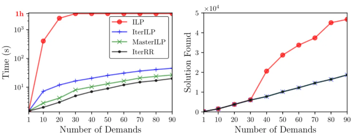
⇥104Figure 3: Time and Value of the solution found by the ILP and by our proposed methods as a function of the number of demands.
method to the one in [2]. We generate two networks in which we place nodes in a unit square. In each of them, we add links according to the Waxman model [22]. The probability of having a link (u, v) is defined as ↵ exp dist(u,v)L where dist(u, v) is the Euclidean distance from node u to
node v, L is the maximum distance between two nodes and ↵, are real parameters in the range [0, 1]. One of the two networks represents the logical IP network, i.e., IP routers and IP links while the other represents the underlying optical network, i.e., cross-connect and fibers. Each IP node is mapped to the closest optical cross-connect and each IP link (u, v) is mapped onto the shortest path between u and v in the physical network. All the IP links using the same physical link are associated to an SRLG. In addition, we add an SRLG for each undirected link. Demands are generated using the model described in [23]. The model takes into consideration the distance factor exp dist(u,v)2L between two nodes u and v, where L is the maximum distance
between two nodes. As a result, the load of the demands between close pairs of nodes is higher with respect to pairs of nodes far apart. Finally, the chain of each demand is composed of 3 to 6 functions uniformly chosen at random from a set of 10 functions. Each VNF-enabled node can run up to 6 network functions. Indeed, a node may not be allowed to run all the network functions. Similarly as in [16], locations are chosen according to their betweenness centrality, an index of the importance of a node in the network: it is the fraction of all shortest paths between any two nodes that pass through a given node. Experiments have been conducted on an Intel Xeon E5520 with 24GB of RAM.
Limits of an ILP-based approach. To study the limits in terms of computing time of an ILP-based approach, we tested our optimization models on a small random topology with 10 nodes, 16 links, and 26 SRLGs. In Figure 3, we show the impact of the number of demands on the execution time. We compare the time necessary to find an optimal solution (on the left) and the value of the solution found (on the right) by the ILP and by our proposed methods. For each experiment, we set a maximum time limit of one hour. If the time limit is exceeded, the solution reported represents the best solution found so far. For just 30 demands, the time needed by Cplex 12.8 to find an exact solution exceeds 1 hour. For large instances, an optimal solution cannot be found using an ILP approach in a reasonable amount of time. On the other hand, the proposed algorithms can compute solutions for larger instances fairly efficiently. Indeed, they only take 1 minute to solve the problem for 90 demands. As the considered network is small, the computed values tend to be close between them. Performances of the optimization
2 3 4
Number of NFVI Nodes
0 2 4 6Required
Bandwidth
⇥104 1.6x 1.3x 1.3x 2.7x 2.5x 2.5x pdh NP GR DP 3 5 7Number of NFVI Nodes
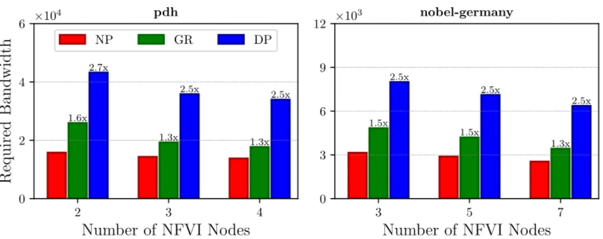
0 3 6 9 12 ⇥10 3 1.5x 1.5x 1.3x 2.5x 2.5x 2.5x nobel-germanyFigure 4: Bandwidth overhead comparison of the global rerouting (GR) and Dedicated Path Pro-tection (DP) schemas with respect to the no-proPro-tection scenario (NP) for pdh and nobel-germany networks. Labels on top of the bars indicate the overhead with respect to the unprotected case.
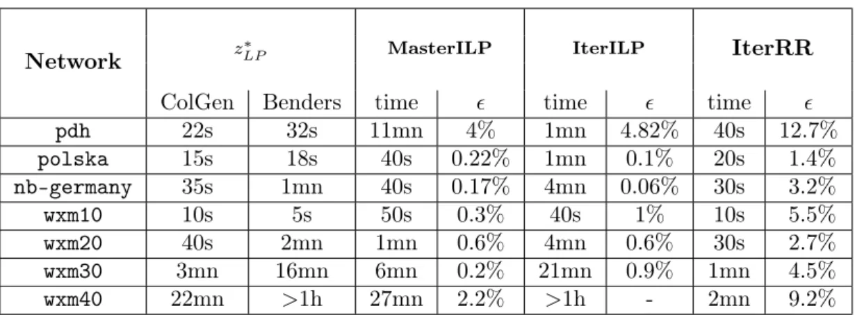
models. Table 1 summarizes the results of our proposed methods for the already presented 3 real networks and for 4 Waxman random networks. Networks are identified as wxm_N with N being the number of nodes. The number of demands is set to be 50, 100, 150, and 200 for the 10, 20, 30, and 40 nodes networks, respectively. Moreover, the number of resulting SRLGs for the Waxman random networks are 22, 40, 53, and 70, respectively. The first column compares the Column Generation (ColGen) and the Benders Decomposition [19] (Benders) techniques to find a fractional solution based on which the heuristics find an integer solution. The Column Generation technique appears to be faster in finding the optimal solution z⇤
LP. Indeed, on the
largest considered network wxm40 only takes 22 minutes to find an optimal solution, while Benders would require more than one hour. The remaining 3 columns refer to our optimization methods. For each method, we present both the time needed to find a solution ˜zILP as well as the ratio
✏ = z˜ILP z⇤LP z⇤
LP with respect to the optimal fractional solution z ⇤
LP. ✏ gives an upper bound on
the maximum overflow to pay in excess with respect to the optimal integer solution z⇤
ILP, since
the optimal integer solution may be larger than the fractional one. Both MasterILP and IterILP allow to find near–optimal solutions. As the size of the network increases, we begin to observe the limits of the IterILP approach, as it solves an ILP for each of the scenario. Although Mas-terILP demonstrates a better scalability and a very high accuracy, for larger networks we have a tradeoff between the time to find the solution and the quality of the solution found. Indeed, for wxm40, IterRR only takes 2 minutes to find a good solution with an accuracy of about 9%, while MasterILP requires 27 minutes to find a solution with an accuracy of 2.2%.
Varying Number of NFVI-enabled Nodes. NFVI nodes are expensive to both purchase and maintain (e.g., hardware, software licenses, energy consumption, and maintenance). If, on one hand, an over-provisioning corresponds to undue extra costs, on the other hand, under-provisioning may result in poor service to user and in Service Level Agreement (SLA) violations. It is thus necessary to find the right trade-off in terms of NFVI nodes in the network design phase. Bandwidth overhead. In Figure 4, we compare the overhead in terms of bandwidth needed in the network by the global rerouting schema and Dedicated Path Protection with respect to the bandwidth needed in the unprotected case. For Dedicated Path Protection we compute, for each demand, two SRLG-disjoint paths, i.e., two paths such that no link on one path has a common risk with any link on the other path. In doing this, we set the bandwidth minimization as an
2 3 4
Number of NFVI Nodes
0 3 6 9 12Num
b
er
of
hops
pdh SP GR 3 5 7Number of NFVI Nodes
03 6 9
12 nobel-germany
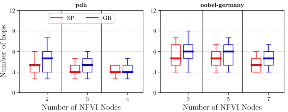
Figure 5: Hops distribution of the backup paths computed by the global rerouting schema (GR) compared with the shortest paths (SP) for pdh and nobel-germany networks. Boxes are defined by the first and third quartiles. Ends of the whiskers correspond to the first and ninth deciles.
optimization task. With an increasing number of VNFI nodes in the network, the required band-width decreases. However, the overhead with respect to the unprotected case tends to remain constant. Indeed, if with global rerouting we only need from 30 to 60% more bandwidth, with dedicated path protection we may need almost 3 times more bandwidth to guarantee the recov-ery. Paths’ delays. In Figure 5, we show the impact of the number of NFVI nodes on the paths’ latencies distribution and compare them with the ones calculated using shortest paths on the layered network. As expected, we see that the number of hops decreases as the number of NFVI-enabled nodes increases. The reason is that, the more NFVI-nodes in a network, the higher the opportunity of easily finding closer NFVI-nodes which can perform some of the required network functions. Another result is that the length of the paths computed using our method are almost as good (in terms of number of hops) as the shortest paths.
6 Experimental evaluation
In this section, we discuss how to implement our proposition with OpenFlow and we evaluate it with Mininet. Our evaluation in realistic conditions shows that implementation choices have a significant impact on the recovery time of protection mechanisms.
6.1 Implementation options
A first option to implement the protection scheme in OpenFlow is to let the OpenFlow controller fully update the flow tables on the switches upon failure. When the controller detects a failure, it sends the new flow tables to the impacted switches. This approach minimizes the memory usage on the switches but incurs high signaling overhead between the controller and the switches, and imposes the latter to install a full flow table at every network change. We refer to this option as full. A variation of this option is to only send the changes to be performed on the flow tables to the switches to reduce the signaling load and the number of flow table updates on the switches. We name this option delta. Another option is to leverage the Multiple Flow Tables capability introduced in OpenFlow 1.3 to pre-install the flow tables for each SRLG failure scenario in the
Full Delta Notification Ideal 101 102 103 Reco very time (ms) GR DP
Figure 6: Recovery time comparison of various imple-mentation options for Global Rerouting (GR) and Dedi-cated Path Protection (DP) for the polska network.
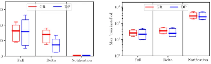
Full Delta Notification 0 10 20 30 40 50 60 Max flo ws changes GR DP Figure 7: Comparison of the number of flow table changes of various imple-mentation options for Global Rerouting (GR) and Dedi-cated Path Protection (DP) for the polska network.
Full Delta Notification 101 102 103 Max flo ws installed GR DP Figure 8: Comparison of the flow table sizes of var-ious implementation options for Global Rerouting (GR) and Dedicated Path Protec-tion (DP) for the polska net-work.
Full Delta Notification Ideal 101 102 103 Reco very time (ms) GR DP
Figure 9: Recovery time comparison of various imple-mentation options for Global Rerouting (GR) and Dedi-cated Path Protection (DP) for the wxm10 network.
Full Delta Notification 0 20 40 60 Max flo ws changes GR DP Figure 10: Comparison of the number of flow table changes of various imple-mentation options for Global Rerouting (GR) and Dedi-cated Path Protection (DP) for the wxm10 network.
Full Delta Notification 100 101 102 103 Max flo ws installed GR DP Figure 11: Comparison of the flow table sizes of var-ious implementation options for Global Rerouting (GR) and Dedicated Path Protec-tion (DP) for the wxm10 net-work.
Network
zLP⇤ MasterILP IterILPIterRR
ColGen Benders
time
✏
time
✏
time
✏
pdh
22s
32s
11mn
4%
1mn
4.82%
40s
12.7%
polska
15s
18s
40s
0.22%
1mn
0.1%
20s
1.4%
nb-germany
35s
1mn
40s
0.17%
4mn
0.06%
30s
3.2%
wxm10
10s
5s
50s
0.3%
40s
1%
10s
5.5%
wxm20
40s
2mn
1mn
0.6%
4mn
0.6%
30s
2.7%
wxm30
3mn
16mn
6mn
0.2%
21mn
0.9%
1mn
4.5%
wxm40
22mn
>1h
27mn
2.2%
>1h
-
2mn
9.2%
Table 1: Numerical results for the proposed optimization models. First column refers to the time needed to find the optimal fractional solution z⇤
LP. We set a maximum time limit of 1h.
The other columns refer to the proposed methods to obtain an integer solution ˜zILP. For each
method, we show the additional time needed and the quality of the solution found, expressed as the ratio ✏ = z˜ILP z⇤LP
z⇤ LP .
switches. When the controller sends a failure notification to a switch, the switch activates the appropriate flow table in only one operation (using goto). This approach minimizes the signaling load and flow table changes but consumes more memory on the switches than the other options. This option is referred to as notification.In the rest of the paper, we study the impact of the technical choices on the recovery time in realistic operational scenarios.
6.2 Experimental setup
Our experimental platform is a dual Intel Xeon E5-2630 CPU server with 128GB of RAM running Mininet 2.2.2and the controller OpenDaylight Oxygen with OpenFlow 1.3.
The routing logic is implemented as a network application orchestrator that communicates with the controller with the HTTP OpenDaylight Northbound API. This approach is recom-mended as it decouples the implementation of the logic from the implementation of the controller. We also made an ideal implementation to assess the best possible performance one could have. It is equivalent to the notification option but is implemented directly in Mininet with Open vSwitch commands. Mininet emulation is centralized, so we are able to synchronize all failure notifications to the switches just after the failure occurs bypassing the controller.
Due to the limited number of CPU cores on our emulation server, we could only evaluate the wxm10 and the polska networks.
6.3 Recovery time
The recovery time is the span of time between a failure event and the moment in which all switches are updated to be in a state that circumvents the failure. To measure the recovery time, we continuously probe end-to-end paths with UDP datagrams. Fig. 6 shows the recovery time for our three OpenDaylight implementation options and the ideal one. It compares our Global Rerouting (GR) protection scheme to the Dedicated Path Protection (DP) scheme. The figure highlights the importance of implementation choices on the recovery time: the notification option significantly outperforms the other options. The ideal implementation also shows that the tools used to implement the protection scheme have a significant impact on the recovery time as,
all things considered, our ideal is just a way of implementing the notification option without a controller. Actually, a significant fraction of the recovery time in OpenDaylight implementations is caused by the usage of the Northbound API. All implementation options offer sub-second recovery time for the considered network. Fig. 6 and 7 show that there is a direct link between the number of changes to be performed on the switches and the recovery time. Fig. 7 reports, for each switch, the maximum number of flow table changes observed expressed in number of flow entries for the three OpenDaylight implementation options. Dedicated path protection has longer recovery time than global rerouting when the full implementation is used. This is because with DP two SRLG-disjoints paths are always provided while GR only provides the paths of the current scenario. On the contrary, DP converges faster than GR with the delta implementation as less path changes are needed for DP than for GR. When notifications are used GR and DP reach the same performance.
6.4 Operational trade-offs
Based on the recovery time, one would recommend to deploy the notification option. However, the reduction of the recovery time comes at the cost of increasing flow table sizes on switches. Fig. 8 reports, for each switch, the maximum observed flow table size expressed in number of flow entries for the three OpenDaylight implementation options. The full option minimizes the number of entries as it only requires to have the flow table for the current routing case. The delta option consumes slightly more space than the full one as the flow table always contains the “no-failure” scenario flow table and the additional flow entries needed to circumvent the current failure. Finally, the notification option has significantly larger flow tables (one order or magnitude more) as flow tables always contain all the potential failure scenarios.
As the robustness of the controller is an orthogonal problem that must be treated by all SDN solutions and because it is already largely studied [24], it was not considered here.
7 Conclusion
In this paper, we studied the ISP network dimensioning problem with protection against a Shared Risk Link Group failure. We considered a path-protection method based on a global rerouting strategy, which makes the protection method optimal in terms of bandwidth. We proposed algorithms to compute the backup paths for the demands which rely on the Column Generation and Benders Decomposition techniques. We validated them experimentally on real-world and on random generated instances. Finally, we showed the applicability of the global rerouting protection method thanks to SDN with a real implementation using OpenDaylight.
References
[1] A. Markopoulou, G. Iannaccone, S. Bhattacharyya, C.-N. Chuah, and C. Diot, “Character-ization of failures in an ip backbone,” in Proceedings of IEEE INFOCOM, 2004.
[2] S. Kandula, D. Katabi, and J.-P. Vasseur, “Shrink: A tool for failure diagnosis in ip net-works,” in Proceedings of the 2005 ACM SIGCOMM workshop on Mining network data. ACM, 2005, pp. 173–178.
[3] D. Papadimitriou, “Inference of shared risk link groups,” Internet-draft: draft-many-inference-srlg-02. txt, 2001.
[4] M. Pióro and D. Medhi, Routing, flow, and capacity design in communication and computer networks. Elsevier, 2004.
[5] N. McKeown, T. Anderson, H. Balakrishnan, G. Parulkar, L. Peterson, J. Rexford, S. Shenker, and J. Turner, “Openflow: enabling innovation in campus networks,” ACM SIGCOMM Computer Communication Review, vol. 38, no. 2, pp. 69–74, 2008.
[6] A. Fumagalli and L. Valcarenghi, “Ip restoration vs. wdm protection: Is there an optimal choice?” IEEE network, vol. 14, no. 6, 2000.
[7] P. Fonseca and E. Mota, “A survey on fault management in software-defined networks,” IEEE Communications Surveys & Tutorials, 2017.
[8] C.-Y. Chu, K. Xi, M. Luo, and H. J. Chao, “Congestion-aware single link failure recovery in hybrid sdn networks,” in Proceedings of IEEE INFOCOM, 2015.
[9] M. Suchara, D. Xu, R. Doverspike, D. Johnson, and J. Rexford, “Network architecture for joint failure recovery and traffic engineering,” in Proceedings of the ACM SIGMETRICS joint international conference on Measurement and modeling of computer systems. ACM, 2011, pp. 97–108.
[10] A. Sgambelluri, A. Giorgetti, F. Cugini, F. Paolucci, and P. Castoldi, “Openflow-based seg-ment protection in ethernet networks,” Journal of Optical Communications and Networking, vol. 5, no. 9, 2013.
[11] A. Tomassilli, G. Di Lena, F. Giroire, I. Tahiri, D. Saucez, S. Pérennes, T. Turletti, R. Sadykov, F. Vanderbeck, and C. Lac, “Poster: Design of Survivable SDN/NFV-enabled Networks with Bandwidth-optimal Failure Recovery,” Proc. of IFIP Networking 2019. [12] A. Kvalbein, A. F. Hansen, S. Gjessing, and O. Lysne, “Fast ip network recovery using
multiple routing configurations,” in Proceedings of IEEE INFOCOM, 2006.
[13] A. Kvalbein, T. Cicic, and S. Gjessing, “Post-failure routing performance with multiple routing configurations,” in Proceedings of IEEE INFOCOM, 2007.
[14] G. Ausiello, A. D’Atri, and M. Protasi, “Structure preserving reductions among convex optimization problems,” Journal of Computer and System Sciences, vol. 21, no. 1, pp. 136– 153, 1980.
[15] I. Dinur and D. Steurer, “Analytical approach to parallel repetition,” in Proceedings ACM STOC 2014.
[16] N. Huin, B. Jaumard, and F. Giroire, “Optimal network service chain provisioning,” IEEE/ACM Transactions on Networking, 2018.
[17] G. Desaulniers, J. Desrosiers, and M. M. Solomon, Column generation. Springer Science & Business Media, 2006, vol. 5.
[18] A. Pessoa, R. Sadykov, E. Uchoa, and F. Vanderbeck, “Automation and combination of linear-programming based stabilization techniques in column generation,” INFORMS Jour-nal on Computing, 2018.
[19] J. F. Benders, “Partitioning procedures for solving mixed-variables programming problems,” Numerische mathematik, vol. 4, no. 1, 1962.
[20] J. Håstad, “Some optimal inapproximability results,” Journal of the ACM (JACM), vol. 48, no. 4, pp. 798–859, 2001.
[21] S. Orlowski, R. Wessäly, M. Pióro, and A. Tomaszewski, “Sndlib 1.0âsurvivable network design library,” Networks, vol. 55, no. 3, 2010.
[22] B. M. Waxman, “Routing of multipoint connections,” IEEE journal on selected areas in communications, vol. 6, no. 9, pp. 1617–1622, 1988.
[23] B. Fortz and M. Thorup, “Optimizing ospf/is-is weights in a changing world,” IEEE journal on selected areas in communications, vol. 20, no. 4, pp. 756–767, 2002.
[24] Y. Zhang, L. Cui, W. Wang, and Y. Zhang, “A survey on software defined networking with multiple controllers,” J. Netw. Comput. Appl., vol. 103, no. C, pp. 101–118, Feb. 2018.
2004 route des Lucioles - BP 93 06902 Sophia Antipolis Cedex
BP 105 - 78153 Le Chesnay Cedex inria.fr