HAL Id: hal-01791511
https://hal-amu.archives-ouvertes.fr/hal-01791511
Submitted on 14 May 2018HAL is a multi-disciplinary open access archive for the deposit and dissemination of sci-entific research documents, whether they are pub-lished or not. The documents may come from teaching and research institutions in France or abroad, or from public or private research centers.
L’archive ouverte pluridisciplinaire HAL, est destinée au dépôt et à la diffusion de documents scientifiques de niveau recherche, publiés ou non, émanant des établissements d’enseignement et de recherche français ou étrangers, des laboratoires publics ou privés.
Interaction of a planar shock wave with a water surface
V. Rodriguez, G Jourdan, A. Marty, A. Allou, J.-D Parisse
To cite this version:
V. Rodriguez, G Jourdan, A. Marty, A. Allou, J.-D Parisse. Interaction of a planar shock wave with a water surface. 31st International Shock wave Symposium (ISSW 31), Jul 2017, Nagoya, Japan. �hal-01791511�
Interaction of a planar shock wave with a water surface
V. Rodriguez1, G. Jourdan, A. Marty
CNRS, IUSTI UMR 7343, Aix-Marseille Université, 13013 Marseille
A. Allou
CEA, DEN, Cadarache, DTN/STCP/LTRS, 13108 Saint Paul lez Durance Cedex, France
J.-D. Parisse
French Air Force Academy, Salon de Provence, BA701 13661 Salon Air.
Corresponding Author’s name: [email protected]
Abstract This work is about experimental study of a planar shock wave which slide over a
water surface. The aim is to observe the air-water interface and the droplet entrainment which is associated. Experiments are performed at atmospheric pressure in a 200×200-mm²-square-cross-section shock tube for depths of 10, 20 and 30 mm and two incident planar shock waves having Mach number of 1.11 and 1.43. We recorded the pressure histories and high-speed visualization to study the flow patterns, surface waves and spray layers behind the shock wave. We observed two different flow patterns with ripples formed at the air-water interface for the weaker shock wave and the dispersion of a droplet mist for the stronger shock wave. We analyzed pressure signals both in the air and in the water at the same location. From these pressure signals we extracted the delay time between the arrival of the compression wave into the water and the shock wave in air at the same location. We show that the delay time evolves with the distance traveled over the water layer, the depth of the water layer and the Mach number of the incident shock wave.
1 Introduction
A planar shock wave which slides over a liquid surface induces complex situations from the perspective of either shock wave refraction or the hydrodynamics instabilities at the air-water interface. This type of problem is of great interest in many applications such as oceanography and industrial accidents. It is essential to understand the shock hydrodynamics associated with both the shock acceleration and the breakup of the liquid layer. However, relatively few experimental works on the subject have been reported in the literature [1-4]. As reported by Epstein et al. [5] and Milton et al. [6], the Kelvin-Helmholtz mechanism could be responsible for the liquid-surface instability and entrainment. The surface tension and the viscosity are the relevant parameters for the transition from surface ripples to the wrenching of the liquid. With the exception of the recent work of Bitter and Shepherd [7], who experimentally studied detonations and deflagration-to-detonation transition in horizontal pipes partially filled with water, there have been no reports of quantitative variables used to describe the pressure evolution. In the present work, we focusing particularly on the pressure histories recorded both in the air and water at the same location for shock waves of Mach 1.11 and 1.43 and several water-layer depths from 10 to 30 mm.
2 Experimental setup
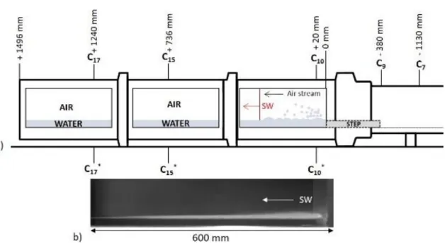
Experiments were conducted at the IUSTI Laboratory of Marseilles to study the interaction of a planar shock wave with a horizontal free water surface [8]. Experiments were performed at atmospheric pressure in a shock tube (T200) with a 200×200-mm²-square-cross-section [9] for depths of 10, 20 and 30 mm and two incident planar shock waves having Mach number of 1.11 and 1.43. We recorded the pressure histories and high-speed visualizations to study the flow patterns, surface waves and spray layers behind the shock wave. Figure 1.a shows the experimental set-up where the T200 shock tube was specifically equipped with a homemade device to complete the experimental chamber of a variable water reservoir of different depths. We placed two pressure transducers in the driven section at stations C7 and C9, and six pressure
transducers were positioned in the test section at stations C10, C10*, C15, C15*, C17 and C17*, as
shown in Fig.1a. We chose this gauge distribution to provide a detailed and accurate pressure map throughout both air and water. Prior to each run, the test section was partially filled with water at room temperature and atmospheric pressure. Image acquisition and slow-motion analysis were obtained via a Photron Fastcam SA1 at 30,000 fps for a spatial resolution of 1,024×176 pixels. In Fig.1b, a picture extracted from an experiment is presented. With these experimental conditions (incident shock wave of Mach 1.43 and a water-layer depth of 10 mm), a thin mist of droplets is ejected into the air and disturbances appear at the air-water interface.
Fig. 1 a) Scheme of the T200 experimental section and principle of the experiment. SW
represents the incident shock wave. b) Picture extracted from an experiment conducted with a water layer having a depth of 10 mm driven by a shock wave with a Mach number of 1.43.
3 Results
We observed two different flow patterns with ripples formed at the air-water interface for the weaker shock wave and the dispersion of a droplet mist for the stronger shock wave (Fig.2).
Fig. 2 Isometric views showing the interaction between a water layer with a depth of 30 mm
and a planar shock wave with Mach number of a) 1.11 and b) 1.43. On each frame is indicated the time (in ms) which is passed since the incident shock wave reaches the beginning of the water layer.
In Fig. 3, we present an example of the pressure histories recorded both in air and water throughout the experimental apparatus.
Fig. 3 Pressure signals recorded during an experiments both in air and water.
As we can see, all pressure gauges record a first pressure increase across the incident shock wave, and later, a second one across the shock wave reflected from the end wall of the driven section. As we can see for this time scale, the signals recorded in air and water are merged.
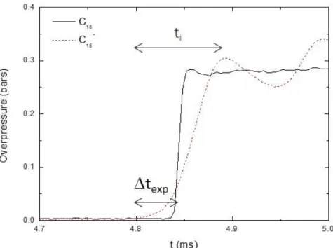
Fig. 4 Pressure increase behind the planar incident shock wave in air (C15 station) and the
compression wave in water (C15*station). Δtexp represents the time gap between the two waves
at the same location and ti represents the duration of the pressure increase in water.
We analyzed pressure signals both in the air and in the water at the same location (Fig.4). From these pressure signals we extracted the delay time between the arrival of the compression wave into the water and the shock wave in air at the same location. We show that the delay time evolves with the distance traveled over the water layer, the depth of the water layer and the Mach number of the incident shock wave.
Fig. 5 Diagrams which represent the scenario proposed by Borisov et al. and used by
Teodorczyk at two times (t0 on the left and t1>t0, on the right) where the incident shock wave is
slower than the speed of sound in water.
In figure 5, we observed that the compression wave does not move at the speed of sound in water but is driven by the planar shock wave in air at any instant. The level of pressure recorded in air and water at the same location are the same (Fig.4). Indeed, to equilibrate the pressure at the air-water interface and to ensure the continuity of the pressure at every instant, a
compression wave transversely propagates in water above the shock wave in air and increases the pressure in the water.
4 Conclusion
We conducted experiments on the interaction of a planar shock wave and a horizontal water layer. The behavior of the water at the air-water interface depending on the strength of the incident shock wave. For the shock wave of Mach 1.11, the patterns at the interface exhibit “ripples” with some macroscopic water droplets ejected into the air. For the shock wave of Mach 1.43, the patterns of the interface have the appearance of a very thin water mist of microscopic droplets and a large wave is moving along the water reservoir. We measure the pressure both in air and water at the same location and at three stations along the experimental chamber of the shock tube. The pressure signals reveal that the propagation of the compression wave in water is driven by the planar shock wave in air at any instant. The delay time between the shock wave in the air and the compression wave in the water and the time over which the pressure increases in water depend on the experimental conditions. These conclusions of pressure signals corroborate the scenario proposed by Borisov et al.
Acknowledgements
This work is supported by CEA Cadarache under contract #4000649074 CJN-001.References
[1] Borisov A.A., Kogarko S.M., Lyubimov A.V., Combust., Explos., and Shock Waves, 1, pp. 31-38 (1965)
[2] Borisov A.A., Gel’fand B.E., Sherpanev S.M., Timofeev E.I., Combust., Explos., and Shock Waves, 17, pp. 86-93 (1981)
[3] Henderson L.F., Ma J-H., Sakurai A., Takayama K., Fluid Dyn Res, 5, pp. 337-350 (1990) [4] Teodorczyk A., Shepherd J.E., technical report no. FM2012.002, Graduate Aeronautical Laboratories, California Institute of Technology (2012)
[5] Epstein M., Fauske H.K., Kubo S., Nakamura T., Koyama K., Nucl Eng Des, 210, pp. 53 -77 (2001)
[6] Milton B.E., Behnia M., Takayama K., Proceedings of the 18th international symposium on
shock waves held at Sendai Japan, 2, pp. 1265-1270 (1991)
[7] Bitter N.P., Shepherd J.E., J Press Vessel Technom, 135, 031203-1 (2013)
[8] Rodriguez V., Jourdan G., Marty A., Allou A., J.-D. Parisse, Exp Fluids, 57, 125 (2016) [9] Houas L., Jourdan G., Schwaederlé L., Carrey R., Diaz F., Shock Waves, 13, pp. 431-434 (2003)
[10] Yarin A.L., Annu Rev Fluid Mech, 38, pp. 159-192 (2006) [11] Yarin A.L., Weiss D.A., J Fluid Mech, 283, pp. 141-173