HAL Id: hal-01392973
https://hal.archives-ouvertes.fr/hal-01392973
Submitted on 5 Nov 2016HAL is a multi-disciplinary open access archive for the deposit and dissemination of sci-entific research documents, whether they are pub-lished or not. The documents may come from teaching and research institutions in France or abroad, or from public or private research centers.
L’archive ouverte pluridisciplinaire HAL, est destinée au dépôt et à la diffusion de documents scientifiques de niveau recherche, publiés ou non, émanant des établissements d’enseignement et de recherche français ou étrangers, des laboratoires publics ou privés.
Metastability of Large Aggregates and Viscosity, and
Stability of The Pearl Necklace Conformation After
Organic Solvent Treatment Of Aqueous Hydrophobic
Polyelectrolyte Solutions
Wafa Essafi, Wifek Raissi, Amira Abdelli, François Boué
To cite this version:
Wafa Essafi, Wifek Raissi, Amira Abdelli, François Boué. Metastability of Large Aggregates and Viscosity, and Stability of The Pearl Necklace Conformation After Organic Solvent Treatment Of Aqueous Hydrophobic Polyelectrolyte Solutions. Journal of Physical Chemistry B, American Chemical Society, 2014, 118, pp.12271 - 12281. �10.1021/jp505852g�. �hal-01392973�
Metastability of Large Aggregates and Viscosity, and Stability of The
Pearl Necklace Conformation After Organic Solvent Treatment Of
Aqueous Hydrophobic Polyelectrolyte Solutions
Wafa ESSAFI 1,*, Wifek RAISSI 1,2, Amira ABDELLI 1,3 and François BOUE 4
1 Institut National de Recherche et d’Analyse Physico-Chimique, Pôle Technologique de Sidi Thabet, 2020 Sidi Thabet- Tunisie
2 Faculté des Sciences de Tunis, département de Chimie, Campus Universitaire, 2092 El
Manar Tunis-Tunisie
3 Faculté des Sciences de Bizerte, département de Chimie, 7021 Jarzouna, Bizerte - Tunisie
4 Laboratoire Léon Brillouin, UMR 12 CNRS - IRAMIS CEA Saclay, 91191 Gif sur Yvette Cedex -France
Abstract:
Aggregates – a phenomenon still not understood, as well as pearl necklace-like chain conformation in aqueous solutions of hydrophobic polyelectrolyte are addressed here, using treatment by an organic solvent. The second appear to be at equilibrium in water, the first appear to be metastable, and surprisingly associated with higher zero shear viscosity. The hydrophobic polyelectrolyte is poly(styrene-co-sodium styrene sulfonate), and the solution treatment is to first add to water an organic solvent, THF, which is then evaporated and replaced by the same amount of water. To investigate polyelectrolyte solutions as a function of THF treatment, we use Small Angle Neutron Scattering in the semi-dilute regime, viscosimetry in dilute and dilute regime (unentangled), and osmometry in similar semi-dilute regime (the contribution of the counterions being dominant).
First, the structure, namely the scattering from all chains, is characterized by a maximum (“polyelectrolyte peak”). Its position, amplitude and scattered intensity at zero angle depend, at a given sulfonation rate of PSS, on the solvent quality through the added amount of organic solvent (THF). This dependence is very pronounced when the sulfonation rate is low (more hydrophobic polyelectrolyte) and is canceled when the sulfonation rate is high (more hydrophilic polyelectrolyte). Second, the viscosity of the polyelectrolyte solutions decreases with THF treatment for the hydrophobic polyelectrolytes. Third, osmometry shows no noticeable increase of the effective charge with THF treatment. It is proposed that the large scale aggregates, especially in the case of very hydrophobic polyelectrolytes, disappear irreversibly with THF treatment, while the pearl-necklace conformation of the chain remains as in its initial state.
Parallel test measurements for a fully hydrophilic polyelectrolyte, poly (sodium-2-acrylamido-2-methylpropane sulfonate) co-(acrylamide): p(AMAMPS) at different sulfonation rates, show no evolution of the structure with THF treatment in the aqueous solution. The same behavior is highlighted by viscosimetry.
Keywords:
poly(styrene-co-sodium styrene sulfonate) Small Angle Neutron Scattering
Intrinsic viscosity
Large Scale Inhomogeneities Osmometry
* Corresponding author. Tel.: +216 21 19 55 23; fax: +216 71 53 76 88; e-mail address: essafi.wafa@inrap.rnrt.tn INTRODUCTION:
Polyelectrolytes (PELs) are polymers containing ionisable groups. Once dissolved in suitable polar solvent such as water, the ion pairs dissociate into charges linked to the polymer backbone and counter-ions dispersed in whole the solution. This combination opens a huge range of opportunities for properties, exploited in industrial as well in living worlds. For a better control of their properties, it is important to well understand the solution structure, i.e. the way polyelectrolyte chains dissolve in water: do they dissolve completely individually, or do they form aggregates? This question is very often addressed for polyelectrolyte solutions, in different situations.
Two main situations are usually considered: when water is a poor solvent for the backbone; polyelectrolytes are called hydrophobic and the process of their solvation is then a combination of electrostatic and hydrophobic interactions. Conversely, backbones of hydrophilic polyelectrolytes are under good solvent conditions in water and interactions have mainly a pure electrostatic nature.
Let us recall the general background about polyelectrolytes chain conformation and interactions in solvent, say water. We start by the dilute regime. While for the hydrophilic polyelectrolytes the single chain is theoretically described as an extended rod-like configuration of electrostatic blobs, 1-3 for hydrophobic polyelectrolytes, the single chain is described in the framework of the pearl-necklace model.4-7 The balance between collapse and extension results in the formation of compact beads (the pearls) joined by narrow elongated strings, in agreement with simulations. 8-12 Experimental results have been reviewed in different papers, like in our previous one, 13 especially on scattering measurements. We summarize them just below.
For poly-(sodium styrene sulfonate)f-(styrene)1-f, it was shown by SAXS that when decreasing the proportion f of hydrophilic monomers, the initially wormlike chains (for f = 1) collapse into more compact objects, further from each other. 14-16 It was proposed that the low internal dielectric constant ε 17 inside the pearls leads to counter-ion/polyion undissociated
pairs, explaining the reduction in osmotic pressure. 18 Another possibility is that counterions condense around the pearls as shown by using X Rays measurements 19 in the same way as they dress the chain string for PSS f = 1.20 For another polymer, it was showed by using addition of miscible bad (or marginal) solvent to water, acetone, that the polyelectrolyte chain undergoes a complete coil to globule collapse transition. 21,22 A third system dealt with anionic chains neutralized by specifically interacting alkaline earth cations, also showing a pearl-string-like conformation. 23,24
In the semi-dilute regime where many chains are interpenetrated with each others, in the case of hydrophilic polyelectrolyte, the chain is a random walk of correlation blobs, 1,2 each blob is an extended configuration of electrostatic blobs, and the correlation length ξ i.e. the mesh size of the isotropic transient network of overlapping chains scales as cp-1/2 where cp
for highly charged hydrophilic polyelectrolyte. 25-27 In the case of hydrophobic polyelectrolyte two regimes have been predicted by Dobrynin et al 6: the string controlled regime and the bead-controlled regime. The string controlled regime exists as long as the pearl size is much smaller than the correlation length ξ; a classical polyelectrolyte behaviour is expected where ξ scales as cp-1/2. When the pearl size becomes of the order of ξ, a bead-controlled semi-dilute
regime is expected with ξ scaling as cp-1/3 and the system behaves as a solution of charged
beads of constant size. Experimentally, two regimes with two scaling exponents being -1/2 and -1/7 have been observed for a solvophobic polyelectrolyte in nonaqueous solvent. 28 For the model hydrophobic PSS in water, the total structure function was measured by Small Angle Scattering studies (SAXS and SANS) and it was found that ξ scales as cp-α where
α decreases from 0.5 to less than 0.4 when decreasing the sulfonation rate of the chain f .16,29 Later, this was also observed by Baigl et al. through SAXS and Atomic Force Microscopy studies. 30,31 Finally, the free counterion concentration in aqueous hydrophobic polyelectrolyte solutions has been studied experimentally and it was found that the effective charge is strongly reduced, 18 compared to the hydrophilic case. 32,33 Condensation has been considered theoretically and recently by including the idea that the pearls can be penetrable to the counterions. 34
Apart from that in the scattering, the presence of low q upturn is most of the time observed for all kinds of polyelectrolyte solutions. It is the signature of large scale aggregates, but their origin remains unanswered: static versus dynamic, hydrophobic versus electrostatic ? To tackle the hydrophobic origin while keeping electrostatic interactions, one route is to monitor the solvent quality (its ability to dissolve the hydrophobic domains and the polyelectrolyte backbone), which we achieved here by adding an organic solvent to water. Indeed, it was shown that the addition of small amount of THF reduces the important low q upturn found with hydrophobic polyelectrolyte solutions: the large aggregates are dissolved by THF addition. 35
Now, we would like to take advantage of another possibility offered by THF plus water mixtures: it is possible, after adding THF, to evaporate it and substitute it by water in order to keep the same concentration. We will call this “THF treatment”. This can enable us to check whether the solution in water is under thermodynamic equilibrium at two scales: at the scale of the pearls and at the scale of the aggregates: do these two kind of objects reform after removing THF back to their initial shape or not ?
So, the aim of the present work is to investigate the effect of THF treatment on the structure of aqueous solutions of sulfonated PSSNa at intermediate sulfonation rates, thus increasing the hydrophobicity of the highly charged polyelectrolyte:
-either by Small Angle Neutron Scattering (SANS) in the semi-dilute regime and thus we determine the total structure function,
-or by viscosimetry measurements in the dilute and semi-dilute unentangled regimes, allowing the determination of the intrinsic viscosity of the different polyelectrolytes as a function of THF treatment.
For comparison, we will study also the behavior of p(AMAMPS), a polyelectrolyte in good solvent in water, at the same intermediate sulfonation rates.
II-MATERIAL
II-1-Polymer synthesis and characterization
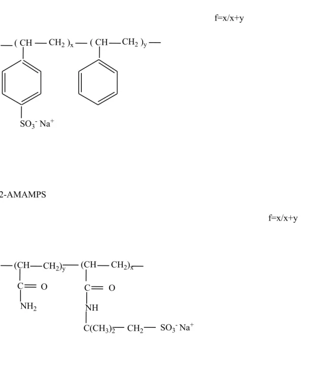
The hydrophobic polyelectrolyte used in this study is a copolymer of styrene and sodium styrene sulfonate (PSSNa) poly-(sodium styrene sulfonate)f–co-(styrene)1-f whose chemical structure is shown on figure 1. It was prepared by post-sulfonation of polystyrene (Mw = 280,000 g/mole of batch n° 16311DB of Sigma-Aldrich Reference 182427) based on the Makowski procedure, 16,36 which enables partial sulfonation and leads to a well-defined polyelectrolyte. 37 We used also a commercial fully charged PSSNa f = 1 (Mw = 666,000 g/mol, its Polydispersity Index Mw/Mn < 1.2) purchased from Polymer Standard Service
(Mainz, Germany), for viscosimetry measurements. The sulfonation rate f of the polyelectrolytes was varied between 0.3 (the limit for solubility in water) and 1 (fully charged). The sulfonation rate f is thus always above the Manning condensation limit for the chemical rate, equal to a/lB ~ 0.3 for PSS in water (a, length of one unit, lB ~ e2/(εkT) ~ 7 Å,
Bjerrum length in water).
The hydrophilic polyelectrolyte also studied in this paper is poly-(sodium-2-acrylamido-2-methylpropane sulfonate)f–co-(acrylamide)(1-f), whose chemical structure is also shown on figure 1. The average molar mass of the monomer is 71 +158*f. It was synthesized by radical copolymerisation of acrylamide with 2-acrylamido-2-methyl propane sulfonic acid, a method reported formerly, 38 which was slightly modified by adjusting the ratio of the two monomers to obtain, after neutralisation, a fraction of ionisable unit (AMPS), f, between 0.3 and 1. Thus these chains are also highly charged polyelectrolytes. Note that both polyelectrolytes (AMAMPS and PSS) are salts of strong acid, bearing SO3- anions as side
groups when ionised, with Na+ counterions. Both backbones are equally flexible (bare persistence length of order 1 nm). So the two polyelectrolytes used in this study differ mainly by the solvation characteristics of their backbone (hydrophobic in the case of PSS, hydrophilic in the case of AMAMPS).
II-2. Preparation of solutions
For the SANS measurements, solutions were prepared by dissolving the dry polyelectrolyte in D2O (used as delivered from Eurisotop) or in the mixture D2O/deuterated
THF noted (THFd) and letting at rest for two days under stirring. The treatment of the
solutions consists in evaporating subsequently THFd, under nitrogen flow and substituting it
exactly by the same volume of D2O. So, the polyelectrolyte solutions are in pure D2O at the
same concentration than initially in the mixture D2O/THFd.
For viscosity or cryoscopy measurements, the dry polyelectrolyte was dissolved in deionised H2O (a resistivity of 18 MΩ.cm) or in a mixture of H2O/THF. After two days under
1-PSS f=x/x+y 2-AMAMPS f=x/x+y
Figure 1: The chemical structure of the polyelectrolytes used in this work, f is the sulfonation rate. ( CH CH2 )x ( CH CH2 )y SO3- Na+ (CH CH2)y (CH CH2)x C O O NH2 C SO3- Na+ CH2 C(CH3)2 NH
All solution concentrations are expressed in mol/L of the corresponding monomer. II-3-SANS measurements
Small Angle Neutron Scattering (SANS) measurements were performed on the PACE spectrometer at the Orphée reactor of LLB, CEA - Saclay, France (www-llb.cea.fr).
A range of scattering vector q = (4π/λ).sin(θ/2) between 0.003 and 0.36 Å-1 was covered by using the following three settings: D = 1m - λ= 6 Å, D = 4.7 m - λ = 13.2 Å and D = 4.7 m - λ = 6 Å. The scattered intensity was recorded on a multidetector with 30 concentric, 1 cm wide rings. The response of each ring was normalized to the (flat) incoherent scattering of light water. Samples were contained in 2 mm thick quartz cells.
All measurements were done at room temperature. The cells were capped and sealed in order to prevent D2O evaporation.
The recorded intensity was corrected for sample thickness, transmission, incoherent and background scattering (the solvent contribution). Using direct beam measurements of Cotton method, 39 the intensities were obtained in absolute units of cross-section; they were then divided by the contrast factor. The SANS data are plotted as S(q) versus q.
II-4-Viscosity measurements
Viscometric measurements of the polyelectrolyte solutions were performed at 25 ± 0.01°C using a SCHOTT viscometer (AVS 470) with a micro Ubbelohde tube of 0.53 mm diameter requiring a sample volume of about 4 ml. Each solution was kept about 5 minutes in the bath prior measurements, for temperature equilibrium.
II-5-Osmometry measurements
The osmometry measurements were performed by mean of a KNAUER vapor pressure osmometer K-7000 which has been designed to exactly measure the total osmolality of fluids. Its principle is based on vapor pressure reduction in solutions corresponding to Raoults law. Two identical thermistors are located in a cell where the gas phase is saturated with solvent vapor. If both thermistors carry drops of pure solvent, the difference in potential between the two is zero. During measurement, one of the solvent droplets is replaced with a droplet of solution (with reduced vapor pressure). This difference is compensated as follows: some vapor of the pure solvent that saturates the gas phase condenses on the droplet of solution. The heat resulting from condensation increases the temperature of the solution droplet, what causes an increase of its vapour pressure, until it equals that of the pure solvent droplet. This increase of the solution temperature is measured with an accuracy of ± 1*10-3 °C
and the number of particles dissolved in the solution, is proportional to this increase. Thus, the osmolality can be determined.
III-RESULTS
The effect of the THF treatment on the hydrophobic polyelectyrolyte solutions was followed mainly by means of two techniques : SANS and viscosimetry.
In what follows, we note “% THF” the percentage by volume of THF used initially in the solvent mixture before evaporation.
III-1-Small Angle Neutron Scattering study in semi-dilute regime
III-1-a- Effect on a hydrophilic polyelectrolyte
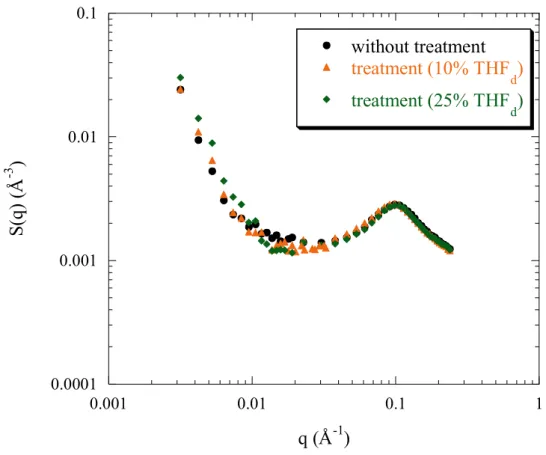
Figure 2 shows the evolution of the SANS profiles without and with treatment from different solvent mixtures of D2O/THFd, for the fully charged p(AMPS) (f = 1) in totally
aqueous solutions in the semi-dilute regime. The polyelectrolyte concentration is kept equal to 0.34 mol/L, for all the samples.
It emerges that the scattering function is independent of the treatment applied to the hydrophilic polyelectrolyte solution, in shape and in intensity. Namely, the position of the peak is unchanged as well as its intensity and the scattered intensity at zero angle (figure 2) is constant whatever the treatment applied to the polyelectrolyte solution.
This indicates that the solvent quality is not improved nor abated as treatment is applied or not to the hydrophilic polyelectrolyte solution.
III-1-b- Effect on a hydrophobic polyelectrolyte
Figure 3 shows the evolution of the scattering profiles for PSSNa f = 0.88 at a concentration of 0.34 mol/L, before and after treatment from different solvent mixtures D2O/THFd, at different angles. We see that all the profiles can be considered as identical, and
so that the scattering function is independent of the treatment applied to this highly charged hydrophobic polyelectrolyte solution, in shape and in intensity. Also, the scattering at the zero q limit (figure 3) is independent of the treatment. So, in the semi-dilute regime, for aqueous solutions of this hydrophobic polyelectrolyte with still a high sulfonation rate, the solvent quality is not improved with treatment. We remain in the situation of the hydrophilic polyelectrolyte solution.
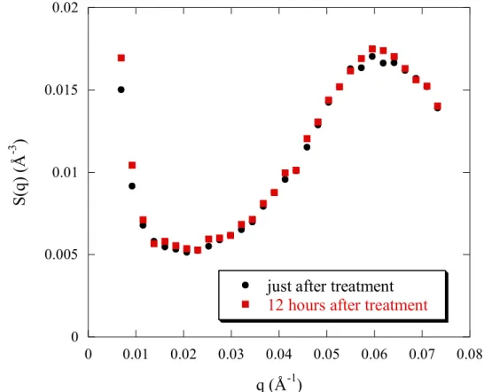
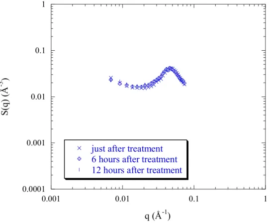
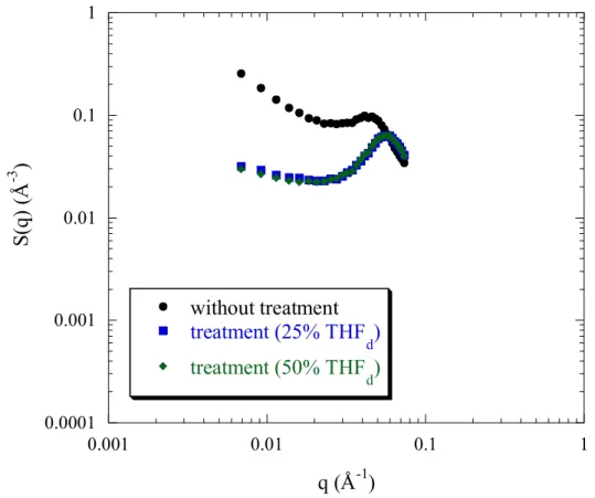
However, if the charge density is decreased, and therefore the hydrophobicity increases, the behaviour becomes different: indeed, for PSSNa f = 0.50 (figure 4a) the peak position q* remains constant with treatment but its height decreases, and also the scattered intensity at small angles decreases. We note that no further structural evolution occurs over time, since the scattering profile recorded after 12 hours is not different from the one just at the end of treatment (figure 4b).
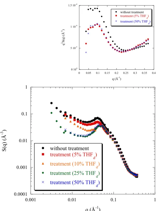
Finally, this trend for change is reinforced when the sulfonation rate decreases furthermore: for f = 0.38 (figure 5), the structure variation with THF treatment is significant: - Obviously, the peak position q* increases slightly and its height decreases (the peak width Δq/q remaining constant). Moreover, the scattered intensity at large angles overlap and are independent of the treatment (figure 5).
- also, at the right of the peak, we notice for the non-treated solution a shoulder (see insert of figure 5). This shoulder transforms into a peak in q2I(q) representation as shown in the insert of figure 5. As earlier commented, 16,29 this is due to the scattering from compact small objects
Figure 2: Evolution of the SANS profiles of totally heavy water solutions of p(AMPS) f = 1 with treatment from initially different solvent mixtures D2O/THFd. The polyelectrolyte
concentration cp = 0.34 mol/L. 0.0001 0.001 0.01 0.1 0.001 0.01 0.1 1 without treatment treatment (10% THF d) treatment (25% THF d) S(q ) (Å -3 ) q (Å-1)
Figure 3: Evolution of the SANS profiles of totally heavy water solutions of PSSNa f = 0.88 with treatment from initially different solvent mixtures D2O/THFd. The polyelectrolyte
concentration cp = 0.34 mol/L. 0.0001 0.001 0.01 0.1 0.001 0.01 0.1 1 without treatment treatment (10% THF d) treatment (25% THF d) S(q ) (Å -3 ) q (Å-1)
Figure 4a: Evolution of the SANS profiles of totally heavy water solutions of PSSNa f = 0.50 with treatment from initially different solvent mixtures D2O/THFd, at intermediate angles. The
polyelectrolyte concentration cp = 0.34 mol/L.
Figure 4b: kinetic of evolution of SANS profiles of PSSNa f = 0.50 in D2O, with treatment
(25% THFd). The polyelectrolyte concentration cp = 0.34 mol/L.
0 0.005 0.01 0.015 0.02 0.025 0 0.01 0.02 0.03 0.04 0.05 0.06 0.07 0.08 without treatment treatment (5% THF d) treatment (25% THF d ) treatment (50% THF d) S(q ) (Å -3 ) q (Å-1) 0 0.005 0.01 0.015 0.02 0 0.01 0.02 0.03 0.04 0.05 0.06 0.07 0.08
just after treatment
12 hours after treatment
S(q
)
(Å
-3 )
Figure 5: Evolution of the SANS profiles of PSSNa f = 0.38 in D2O without and with
treatment from initially different solvent mixtures D2O/THFd. The polyelectrolyte
concentration cp = 0.34 mol/L. The insert represents the Kratky plot of the intensity scattered
by some of the same solutions (5% and 50% THFd).
0 100 5 10-5 1 10-4 1.5 10-4 0 0.05 0.1 0.15 0.2 0.25 0.3 0.35 0.4 without treatment treatment (5% THFd) treatment (50% THF d) q 2 S( q) ( Å -5 ) q (Å-1) 0.0001 0.001 0.01 0.1 1 0.001 0.01 0.1 1 without treatment treatment (5% THF d) treatment (10% THF d) treatment (25% THF d) treatment (50% THF d) S(q ) (Å -3 ) q (Å-1)
, which are the pearls. As a function of treatment, the shoulder is reduced but it still exists, as unambiguous shown in insert of figure 5.
- for the low q region, changes are noticeable for f = 0.38. The upturn at q→0 decreases considerably with treatment and as a consequence on the right of the foot of the upturn, the plateau part widens progressively and also the plateau height lowers.
- at the lowest q, the scattered intensity decreases with treatment. These effects grow in strength with increasing THF from 5 to 25%. However, there is saturation when passing from a treatment of 25% THFd to 50% THFd. The two curves are perfectly superimposed.
Finally, as in the case of PSSNa f = 0.50, no structural evolution occurs over time, after 12 hours (figure 6a).
For f = 0.38, we have also some measurements at a lower concentration, 0.17 mol/L (figure 6b) and at higher concentration, 0.50 mol/L (figure 6c). We observe the same effects.
III-2-Viscometric Study in dilute and semi-dilute unentangled regime
III-2-a- Behaviour of an Hydrophilic polyelectrolyte
The variation of the reduced viscosity versus the concentration of AMAMPS f = 0.35 with treatment, is presented in figure 7a. All the curves show a polyelectrolyte behaviour, namely a typical upturn of the reduced viscosity ηred at low concentrations. This is classically
explained as follows: when the polyelectrolyte concentration decreases, the screening - due mostly to the free counter-ions - is reduced: the range of the intramolecular repulsion - the Debye length - is increased. Thus the polyelectrolyte chain becomes more extended and consequently ηred increases. 40,41
We also see on figure 7b that THF treatment does not affect the reduced viscosity of the fully charged of p(AMPS) f = 1 polyelectrolyte solution. This agrees with the idea of a conformation unaffected by THF treatment in the corresponding concentration range for hydrophilic PEL.
III-2-a- Behaviour of an Hydrophobic polyelectrolyte
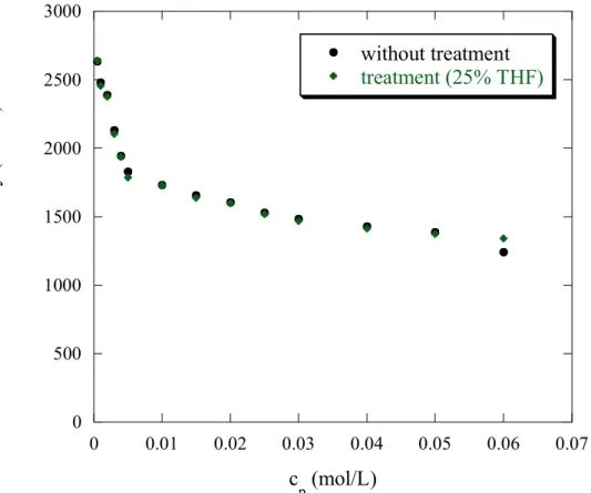
The effect of THF treatment on the viscosity of the PSSNa hydrophobic polyelectrolyte aqueous solutions at 25°C, is shown on figure 8.
For the two extreme sulfonation rates, the PSSNa presents like for the hydrophilic polyelectrolyte AMAMPS, the typical polyelectrolyte behaviour: the reduced viscosity increases as the concentration decreases. The explanation is the same as given for AMAMPS.
When treatment is applied, the evolution is different for the two f’s. For f = 1 (highly charged PSSNa), figure 8a shows that the reduced viscosity is independent of the THF treatment, like for AMAMPS: PSSNa f = 1 behaves as an hydrophilic polyelectrolyte. However, the effect of THF treatment is different for the second f: indeed, for f = 0.38, the reduced viscosity decreases with THF treatment. Moreover, the reduced viscosity of PSSNa f = 0.38, as a function of polyelectrolyte concentration, treated from a solvent mixture : 90% H2O/10% THF overlaps that obtained from a solvent mixture 75% H2O/25% THF. So,
Figure 6a: kinetic of evolution of SANS profiles of PSSNa f = 0.38 in D2O, with treatment
(50% THFd). The polyelectrolyte concentration cp = 0.34 mol/L.
Figure 6b: Evolution of the SANS profiles of PSSNa f = 0.38 in D2O without and with
treatment from initially different solvent mixtures D2O/THFd. The polyelectrolyte
concentration cp = 0.17 mol/L. 0.0001 0.001 0.01 0.1 1 0.001 0.01 0.1 1
just after treatment 6 hours after treatment 12 hours after treatment
S(q ) (Å -3 ) q (Å-1) 0.0001 0.001 0.01 0.1 1 0.001 0.01 0.1 1 without treatment treatment (5% THF d) treatment (10%THF d) S(q ) (Å -3 ) q (Å-1)
Figure 6c: Evolution of the SANS profiles of PSSNa f = 0.38 in D2O without and with
treatment from initially different solvent mixtures D2O/THFd. The polyelectrolyte
concentration cp = 0.50 mol/L. 0.0001 0.001 0.01 0.1 1 0.001 0.01 0.1 1 without treatment treatment (25% THF d) treatment (50% THF d) S(q ) (Å -3 ) q (Å-1)
Figure 7a: Evolution of the reduced viscosity versus the polyelectrolyte concentration for AMAMPS f = 0.35, as a function of treatment at 25°C.
Figure 7b: Evolution of the reduced viscosity versus the polyelectrolyte concentration for p(AMPS) f = 1, as a function of treatment at 25°C.
0 500 1000 1500 2000 2500 3000 0 0.01 0.02 0.03 0.04 0.05 0.06 0.07 without treatment treatment (25% THF) Re du ce d vi sc os ity (L/ m ol ) c p (mol/L) 0 500 1000 1500 2000 0 0.01 0.02 0.03 0.04 0.05 0.06 0.07 without treatment treatment (25% THF) Re du ce d vi sc os ity (L/ m ol ) c p (mol/L)
Figure 8a : Evolution of the reduced viscosity versus the polyelectrolyte concentration for PSSNa f = 1, as a function of treatment at 25°C.
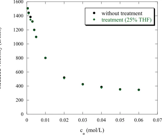
Figure 8b: Evolution of the reduced viscosity versus the polyelectrolyte concentration for PSSNa f = 0.38, as a function of treatment at 25°C.
0 200 400 600 800 1000 1200 1400 1600 0 0.01 0.02 0.03 0.04 0.05 0.06 0.07 without treatment treatment (25% THF) Re du ce d vi sc os ity (L/ m ol ) c p (mol/L) 0 20 40 60 80 100 0 0.05 0.1 0.15 0.2 without treatment treatment (5%THF) treatment (10% THF) treatment (25% THF) Re du ce d visc os ity (L/ m ol) c p (mol/L)
III-3-Osmometry measurements
Assuming that the osmolality cosmol of the polyelectrolyte solution measured directly by
the osmometer, is proportional to the concentration of free counterions of the polyelectrolyte solution, so the ratio cosmol/cp is proportional to the effective charge of the polyelectrolyte. To
convert cosmol/cp in term of effective charge, we need first a reference which is the p(AMPS) f
= 1, for which the effective charge is equal to 0.36. 18 On the other hand, the contribution of the polyelectrolyte chain and the residual salt of the solvent to the osmolarity were subtracted by measuring the osmolarity of the corresponding "neutral" polyelectrolyte p(AM).
We use the following empirical formula to determine the effective charge: 36 . 0 ) c / c ( ) c / c ( ) c / c ( ) c / c ( f ) AM ( P p osmol 1 f ) AMPS ( P p osmol ) AM ( P p osmol PSS p osmol eff ∗ − − = = (Eq.1)
The osmolarity of all the polyelectrolyte solutions was measured at a concentration of 0.17 mol/l, corresponding to a regime where the osmolarity of the polyelectrolyte solution provides only from the free counterions and hence the contribution of the polymer is negligible. 18
Figure 9 shows the evolution of the effective charge feff of PSSNa f = 0.38 as a function of treatment, obtained by vapour pressure osmometry at a concentration of 0.17 mol/L. It emerges first that the effective charge for the polyelectrolyte solution without treatment determined by vapour pressure osmometer is very close to that determined by osmotic-pressure measurements 18 and which is found to be around 0.07, highly reduced to the value of 0.36 found for the hydrophilic p(AMPS) f = 1. On the other hand, the most striking result is that the effective charge remains constant with treatment. So, the THF treatment does not affect the effective charge of the single polyelectrolyte chain.
In summary of the Results section, when the polyelectrolyte has a clear cut hydrophobic character in water, viscosimetry as well as scattering suggest an evolution towards a limit structure, as a function of THF treatment indicating an irreversible disappearance of the large scale aggregates in separated chains.
IV-DISCUSSION
IV-1-Small Angle Neutron Scattering study in semi-dilute regime
IV-1-a- Effect of THF treatment on hydrophilic polyelectrolyte
Concerning the hydrophilic polyelectrolyte, p(AMPS) f = 1, it emerges firstly from data that the scattering is independent of THFd treatment. The curves for 0%, 10% and 25%
THFd, just overlap.
This means that the polyelectrolyte chain network of the p(AMPS) has its mesh size and degree of order unchanged, and that the effective charge remains constant with THF treatment. Finally, the constancy of the scattered intensity at the lowest q value available
(3.10-3 Å-1) also suggests that the effective charge is constant, if we assume that S(q→0) which is related to the osmotic compressibility is ~ 1/feff. Knowing also that for most of
Figure 9: Evolution of the effective charge feff as a function of THF treatment, for PSSNa f = 0.38, obtained by vapour pressure osmometry at a concentration of 0.17 mol/L.
0 0.1 0.2 0.3 0.4 0 5 10 15 20 25 30 without treatment treatment (5% THF) treatment (10% THF) treatment (25% THF) E ffe cti ve c ha rg e Treatement (%THF)
polyelectrolyte solutions, measurements at lower q are perturbed by a low q upturn generally observed. Let us briefly detail below.
Intermediate and large q behaviour. The analytical expression for the dependence of the
position of the maximum in the scattering intensity q* is predicted by the theoretical models of the semi-dilute polyelectrolyte solutions derived from the isotropic phase model (de Gennes et al 1) and by Dobrynin et al 2 for polyelectrolytes in good solvents, therefore far from theta temperature Θ. The chain is a random walk of correlation blobs of size ξ, each of which is an extended configuration of electrostatic blobs of ge monomers inside the blob diameter D.
Therefore ξ is close to a geometrical distance between rod-like strands of chains and depends on their effective linear density of segments (ge/D), which we will define as equal to B/a,
defining a as the segment length and B as in Ref. 2:
(Eq.2)
Thus we consider now the case of good solvent (T>> Θ): ge and D are determined by the fact
that the total electrostatic energy between charges inside the electrostatic blob is ~ kBT, due to
thermal agitation, with no influence of the distance to theta and using again feff = a/lB, q* writes now:
(Eq.3) Following equation 3, the THF treatment should not affect the position q* since the dielectric constant and temperature are constant, which is in agreement with our experimental results. Concerning the variation of S(q*), it can be expressed by 1 :
(Eq.4) (g is the number of monomer inside the blob ξ).
We do not observe experimentally any variation of S(q*) with THF treatment, which is in agreement with the theoretical predictions.
Low q behaviour. According to the Dobrynin model 2 :
(Eq.5)
(where is the polymer volume fraction, Vmolecular is the molecular volume of the PSS-;
Vmolecular = VMolar /NAvogadro and VMolar is the PSS- molar volume ).
This should lead to a flat scattering at q tending to zero. However on top of this predicted scattering, scattering from aggregates are known to be responsible for the low q upturn. Since the low q scattering does not vary neither in the upturn nor in the flat part (0.01 Å-1 < q < 0.02
2 / 1 pa c B ⎟ ⎟ ⎠ ⎞ ⎜ ⎜ ⎝ ⎛ ∝ ξ
( )
1/7( )
1/7 B 2 / 1 p 7 / 2 eff 7 / 1 B 2 / 1 p T l a c f a l a c B 2 * q ε ξ π ∝ ∝ ⎟ ⎠ ⎞ ⎜ ⎝ ⎛ ∝ ⎟ ⎟ ⎠ ⎞ ⎜ ⎜ ⎝ ⎛ ∝ ⎟⎟ ⎠ ⎞ ⎜⎜ ⎝ ⎛ ∝ − − Θ >> T( )
3/7 3 3 p q* T c g 2 S *) q ( S − − ε = ≈ ξ ≈ ≈ ⎟⎟ ⎠ ⎞ ⎜⎜ ⎝ ⎛ ξ π = T>>Θ molecular eff p p p V . f c kTc ) 0 q ( S = Φ Π ∂ ∂ = → p ΦÅ-1), we can propose that both feff and the aggregate shape are not changed by THF treatment. Consistent with this, is the fact that the origin of the aggregates does not arise from hydrophobic attractive interactions, hence they have most probably an electrostatic origin.
IV-1-b- Effect of THF treatment on hydrophobic polyelectrolyte
This evolution of the scattered intensity is more pronounced as f decreases.
• for f = 0.88 and in the q ~ q*, the change with THF treatment is limited to the low qs : more precisely the scattering minimum (corresponding to the flat part region, q around 0.02 Å-1) is slightly lowered. Following what explained just above, this can be assigned to (i) an increase of the effective charge, or (ii) to less scattering from large aggregates. If (i) was right, the peak position should moves to higher q’s, which is not the case. Hence this decrease of the intensity is better related to a lower scattering from aggregates.
• for f = 0.50 and in the q ~ q*, the intensity of the peak decreases with THF treatment (with a saturation for 25% and beyond). This is surprising because the peak height is
predicted by Eq.4 to scale as . Since q* and cp are constant, S(q*)
should remain constant with treatment. At the intermediate q range (q < 0.03 Å-1), the flat part of the scattered intensity decreases with THF treatment. This decrease of the flat part should be ascribed to a less scattering large scale aggregates. Concerning the kinetics evolution of the scattered intensity, the lack of evolution after 12 hours (figure 4b) means that the initial hydrophobic aggregates disappear after treatment, irreversibly: they were not at the equilibrium state.
• for f = 0.38 (figure 5), changes are strong :
- in the range q ~ q*, the intensity of the peak decreases significantly with THF treatment (with saturation from 25% THFd) and the peak is displaced to higher q. Note
that for hydrophobic polyelectrolyte where T < Θ, q* is expressed by 2,6 :
2 / 1 p 4 / 1 eff 4 / 1 (f ) c * q − τ ∝ for T < Θ (Eq.6) where τ =
(
)
Θ −Θ T . So, an increase of q* is attributed to an increase of the concentration or of the effective charge (τ remains constant since temperature is kept constant and the used solvent is usually water). From osmometry measurements, we deduce that the effective charge remains constant with THF treatment; hence the displacement of the peak should be attributed to an increase of the PEL concentration. This should only come from the dissolved aggregates; the concentration change would however be strong: the shift from q* = 0.0413 Å-1 to q* = 0.0481 Å-1 corresponds to an increase from 0.34 mol/L to 0.58 mol/L, according to the variation law of q* as a function of cp
for PSSNa f = 0.38, before treatment.
- in the low q region, the scattered intensity at q→0 measured just at the foot of the upturn q ≈ 0.020641 Å-1, is decreased by THF treatment in two ways:
- the upturn at q → 0 is reduced significantly: this can be interpreted as the reduction of large hydrophobic aggregates.
- the value of the ‘flat part’ is lowered down and also this region widens. Since
we assume from osmometry measurements a constant osmotic compressibility, it
3 p 3 p c q* c *) q ( S − ≈ ξ ≈
can be related to less scattering objects and so to a decrease of aggregates scattering. The saturation effect above 25% THFd treatment suggests that the aggregates that are
likely to dissolve have disappeared entirely, at least with this kind of treatment. Note that despite the decay of the scattered intensity in the whole low q region, it remains however higher than for the highly charged PSSNa f = 0.88. This result shows that the effective charge of PSSNa after treatment is lower than that of PSSNa f = 0.88, which is expectable, and that even after treatment the large scale inhomogeneities for f = 0.38 are still scattering more than the well-known large scale inhomogeneities characteristics of pure polyelectrolyte solutions, attributed to electrostatics.
• Concerning the behaviour at the right of the peak (q ~ 0.05 - 0.4 Å-1) including the domain of existence of the “second shoulder”, 16 enhanced in the q2S(q) representation (insert of figure 5), the abscissa of the shoulder does not vary with THF treatment; hence the pearl size remains constant with THF treatment.
Finally, we can compare the variation observed here with the one observed with added THF. For 10% added THF (see figure SI1 or A1 in Supporting Information or in Appendix of Ref 35), the shift of q* is shifted towards 0.05 Å-1, so only slightly more than for THF treatment: part only of the effect is reversible. But when amount of added THF reaches 25%, q* becomes 0.065 Å-1: in this case most of the effect of THF is reversible. So, the conformational change of the polyelectrolyte chain in presence of THF addition is largely reversible after THF treatment.
IV-2-Viscometric study in dilute and semi-dilute unentangled regimes
IV-2-a- Hydrophilic polyelectrolyte
The viscosity of polyelectrolyte solutions in semi-dilute unentangled regime can be described by the evolution of the 1/ηred = f(cp1/2). We will use this representation, which gives
often a linear variation in practice, in agreement with the so-called “Fuoss law” 40 :
ηred = (Eq.7)
Though of empirical origin, Eq.7 is recovered by the theory of Dobrynin and al for hydrophilic polyelectrolytes. 2 It is frequently used to determine the intrinsic viscosity values [η] for polyelectrolytes in aqueous solution, from the intercept of the inverse of the Fuoss representation.
For the p(AMPS) f = 1, as well as for f = 0.35 with the different solvent compositions, plotting 1/ηred versus , gives linear evolutions for all the solvent compositions (Figure 10).
Concerning THF treatment, we note that all curves overlap. The intercept A remains constant with THF treatment as shown on figure 10.
Let us compare with the evolution under THF treatment of SANS, which also show no change: we conclude that viscosimetry and SANS appear complementary methods and show a fair correlation (though the same concentration ranges are most of the time not even overlapping: maximum Cpmax for η is 0.06 mol/L to compare with 0.34 mol/L for S(q)) - see
Figure 7a; 7b and 8a, except for PSSNa f = 0.38, where Cpmax is 0.17 mol/L - see Figure 8b.
(
0.5)
p Pc 1 A + 5 . 0 p c
Figure 10a: Fit of the viscometry data AMAMPS f = 0.35 at 25°C as a function of treatment with the Fuoss Equation.
Figure 10b: Fit of the viscometry data p(AMPS) f = 1 at 25°C as a function of treatment with the Fuoss Equation.
0 0.0002 0.0004 0.0006 0.0008 0 0.05 0.1 0.15 0.2 0.25 without treatment treatment (25% THF) 1/ R ed uc ed v is co ps ity (m ol /L ) c p 0.5 (mol/L)0.5 0 0.0005 0.001 0.0015 0.002 0.0025 0 0.05 0.1 0.15 0.2 0.25 without treatment treatment (25%THF) 1/ R ed uc ed v is co ps ity (m ol /L ) c p 0.5 (mol/L)0.5
IV-2-b- Hydrophobic polyelectrolyte
For the hydrophobic polyelectrolyte, the same agreement with Fuoss law is observed for all PSS sulfonation rates and all THF treatments (figures 11a and 11b).
Firstly, for f = 1, there is no effect of THF treatment (figure 8a), the same behaviour as found for the hydrophilic polyelectrolyte AMAMPS.
Secondly, for f = 0.38, the viscosity decreases considerably with THF treatment. In other words, the hydrodynamic volume of the PSSNa decreases with THF treatment. Fuoss law 40 fits well the experimental results here also (figure 11b) and, accordingly, the extracted intrinsic viscosity decreases with THF treatment (see figure 11c). Note that opposite to what expected if the chain was expanding (as observed when simply adding THF). What is more revealing with this representation is that the slope of the Fuoss representation remains
constant with THF treatment. According to the theories of Witten 42 and Rabin, 43 this slope is related to the effective charge feff of the polyelectrolyte; we deduce that feff remains constant with THF treatment. This behavior is in agreement with osmometry measurements.
To conclude this paragraph, the decrease of the intrinsic viscosity and thus the hydrodynamic volume of the chain can be related only to the dissolution of the hydrophobic large scales aggregates.
Under this assumption, we thus find agreement between SANS and viscosimetry measurements.
To end this discussion it is interesting to compare with the case of solutions with added THF, without evaporation : in presence of THF the aggregates vanish, but the chains expand, which is the dominant effect for viscosity and results in an increase. 35 This is schematized in Figure 12 a and b. After evaporation (figure 12 c), the chains recover their initial contracted conformation, so that their contribution to viscosity returns to the value before treatment. But the aggregates contribution is reduced by the treatment, so that the viscosity decreases even more.
V-CONCLUSION
To summarize our results, the effect of THF treatment is negligible for hydrophilic PELs, AMAMPS or PSSNa f ≈ 0.9-1, hardly visible for PSSNa f = 0.50, and noticeable for low sulfonation rate (PSSNa f = 0.38). These results are observed both on the scattering, related to the spatial structure of the solution, in the semi-dilute regime of concentration, and on the viscosity, measured from the dilute to the semi-dilute concentration range (sometimes comprising the value used for scattering).
From this point of view, there is thus a good agreement between SANS and viscometry. But the sign of the variation of the two quantities requires more discussion. This can be enlightened by the complementary osmometry measurements, which are consistent with the latter, though they actually require even more subtlety in the discussion. We will focus on the hydrophobic case, f = 0.38. The variation of SANS results comprises two different behaviours:
Figure 11a: Fit of the viscometry data PSSNa f = 1 at 25°C as a function of treatment with the Fuoss Equation.
Figure 11b: Fit of the viscometry data PSSNa f = 0.38 at 25°C as a function of treatment with the Fuoss Equation.
0 0.0005 0.001 0.0015 0.002 0.0025 0.003 0 0.05 0.1 0.15 0.2 0.25 without treatment treatment 25% THF 1/ R ed uc ed v is co ps ity (m ol /L ) c p 0.5 (mol/L)0.5 0 0.02 0.04 0.06 0.08 0 0.05 0.1 0.15 0.2 0.25 without treatment treatment (5% THF) treatment (10% THF) treatment (25% THF) 1/ R ed uc ed v is co si ty (L/ m ol ) c p 1/2 (mol/L)0.5
Figure 11 c: The evolution of the extrapolated intrinsic viscosity for PSS f = 0.38 with treatment. 0 50 100 150 200 250 300 0 5 10 15 20 25 30 without treatment treatment (5% THF) treatment (10% THF) treatment (25% THF) In tri ns ic Visc os ity (L/ m ol ) treatment (%THF)
• (i) at low q, the signal from aggregates decreases clearly : the simplest explanation is some aggregates have dissolved in presence of THF and do not reform when back in water. Their dissolution is irreversible.
• (ii) at intermediate and large q, the peak is shifted to large q. This could be explained by a better dissolution of aggregates into separate polyelectrolyte chains, while the conformation of the polyelectrolyte chains remains constant with the treatment. This behaviour corroborates that the polyelectrolyte is at equilibrium state in water. the conformation of the polyelectrolyte chain remaining constant with THF treatment is also correlated to a constancy of the effective charge feff with THF treatment, as also revealed by the osmometry measurements.
• the viscosity varies but in Fuoss representation, the slope which is attributed to feff, is the same as well, confirming the result of the constancy of the effective charge.
So, we proposed that the shift of q* could be due to an increase of concentration due to the dissolution of the aggregates.
The second interesting point to discuss is the sign of the variation of the viscosity: it decreases. The opposite is expected from a more extended chain, as was actually observed in our former papers. 13,35 Hence we are driven to this explanation: this decrease can be due to the dissolution of some aggregates (figure 12). Such possibility points a striking role of aggregates or other types of large scale concentration fluctuations in the viscosity of polyelectrolyte solutions.
ACKNOWLEDGMENTS
We thank Souha BEN MAHMOUD and Ons MHIRI for their helpful in the preparation of some polyelectrolyte solutions.
SUPPORTING INFORMATION AVAILABLE
The Evolution of the SANS profiles with the percentage of added THF to aqueous solutions of PSSNa f = 0.38. The polyelectrolyte concentration is cp = 0.34 mol/L. The insert represents the Kratky plot of the intensity scattered by the same solutions. (reprint from Figure 5 in ref. 35). This information is available free of charge via the Internet at http://pubs.acs.org
Figure 12: Schematization of the hydrophobic polyelectrolyte aqueous solution (a), after THF addition (b) and after THF treatment (c).
REFERENCES
(1) De Gennes, P.G.; Pincus, P.; Velasco, R. M.; Brochard, F. Remarks on Polyelectrolyte Conformation. J. Phys.(Paris) 1976, 37, 1461-1473.
(2) Dobrynin, A. V.; Colby, R. H. and Rubinstein, M. Scaling Theory of Polyelectrolyte Solutions. Macromolecules 1995, 28, 1859-1871.
(3) Barrat, J. L.; Joanny J. F. in Advances in Chemical Physics; Prigogine, I., Rice, S.A., Eds.;Wiley:New York, 1996; vol. X C IV, and references therein.
(4) Dobrynin, A. V.; Rubinstein, M.; Obukhov, S. P. Cascade of Transitions of Polyelectrolytes in Poor Solvents. Macromolecules 1996, 29, 2974-2979.
(5) Kantor, Y.; Kardar, M. Excess Charge in Polyampholytes. Europhys.Lett.1994, 27, 643-648.
(6) Dobrynin, A.V.; Rubinstein, M. Hydrophobic Polyelectrolytes. Macromolecules 1999, 32, 915-922.
(7) Dobrynin, A.V.; Rubinstein, M. Counterion Condensation and Phase Separation in Solutions of Hydrophobic Polyelectrolytes. Macromolecules 2001, 34,1964-‐1972.
(8) Micka, U.; Holm, C.; Kremer, K. Strongly Charged, Flexible Polyelectrolytes in Poor Solvents - A Molecular Dynamics Study. Langmuir 1999, 15, 4033-4044.
(9) Limbach H.J.; Holm, C.; Kremer, K. Structure of Polyelectrolytes in Poor Solvent.
Europhys. Lett. 2002, 60, 566-572.
(10) Limbach H.J.; Holm, C. Single-Chain Properties of Polyelectrolytes in Poor Solvent. J.
Phys. Chem. B. 2003, 107, 8041-8055.
(11) Schweins, R; Huber, K. Particle Scattering Factor of Pearl Necklace Chains. Macromol
Symp. 2004, 211, 25-42.
(12) Liao, Q.; Dobrynin, A.V.; Rubinstein, M. Counterion-Correlation-Induced Attraction and Necklace Formation in Polyelectrolyte Solutions: Theory and Simulations. Macromolecules
2006, 39, 1920-1938.
(13) Essafi, W.; Haboubi, N.; Williams, C.E.; Boué, F. Weak Temperature Dependence of Structure in Hydrophobic Polyelectrolyte Aqueous Solution (PSSNa): Correlation between Scattering and Viscosity. J.Phys.Chem. B, 2011, 115, 8951-8960.
(14) Williams, C.E. Electrostatic Effects in Soft Matter and Biophysics, edited by Holm C., Kekicheff P. and Podgornik R., NATO Science Series., vol. 46 (Kluwer Academic Publishers, Dordrecht) 2001, 487-586.
(15) Baigl, D.; Sferrazza, M.; Williams, C.E. On the Pearl Size of Hydrophobic Polyelectrolytes. Europhys. Lett. 2003, 62, 110-116
(16) Essafi, W.; Lafuma F.; Williams, C. E. in Macro-ion Characterization. From Dilute
solutions to complex fluids, K.S. Schmitz, ed., ACS Symposium Series 548, 1994, 278-286.
(17) Essafi, W.; Lafuma, F.; Williams, C.E. Effect of Solvent Quality on the Behaviour of Highly Charged Polyelectrolytes. J. Phys. II 1995, 5, 1269-1275.
(18) Essafi, W.; Lafuma, F.; Baigl, D.; Williams, C.E. Anomalous Counterion Condensation in Salt-Free Hydrophobic Polyelectrolyte Solutions: Osmotic Pressure Measurements.
Europhys. Lett. 2005, 71, 938-944.
(19) (a) Combet, J.; Rawiso, Boué, F. poster presented at: WE-Heraeus-Seminar Understanding the Self Organization of Charged Polymers, Physikzentrum Bad
Honnef Germany, 4-6 April 2005; XX Congress of the International Union of Crystallography IUCr 2005, Florence Italy, 23-31 August 2005; 6th International Symposium on Polyelectrolytes 2006, Dresden, Germany, 4-8 September 2006, (b) Heinrich, M.; Structures de Solutions Aqueuses de Polyélectrolytes en Etoile. Ph. D, Strasbourg Louis Pasteur University, 1998.
(20) Combet, J.; Rawiso, M.; Rochas, C.; Hoffmann S. Boué, F. Structure of Polyelectrolytes with Mixed Monovalent and Divalent Counterions : SAXS Measurements and Poisson-Boltzmann Analysis. Macromolecules, 2011, 44, 3039-3052.
(21) Aseyev, V.O.; Tenhu, H.; Klenin, S.I. Contraction of a Polyelectrolyte upon Dilution. Light-Scattering Studies on a Polycation in Saltless Water-Acetone Mixtures.
Macromolecules 1998, 31, 7717-7722.
(22) Aseyev, V.O.; Klenin, S.I.; Tenhu, H.; Grillo, I.; Geissler, E. Neutron Scattering Studies of the Structure of a Polyelectrolyte Globule in a Water−Acetone Mixture. Macromolecules
2001, 34, 3706-3709.
(23) Schweins, R.; Lindner, P.; Huber, K. Calcium Induced Shrinking of NaPA Chains: A SANS Investigation of Single Chain Behavior. Macromolecules 2003, 36, 9564-9573.
(24) Goerigk, G.; Schweins, R; Huber, K.; Ballauf, M. The distribution of Sr2+ Counterions Around Polyacrylate Chains Analyzed by Anomalous Small-Angle X-ray Scattering.
Europhys. Lett. 2004, 66, 331-337
(25) Essafi, W.; Lafuma, F.; Williams, C.E. Structural Evidence of Charge Renormalization in Semi-Dilute Solutions of Highly Charged Polyelectrolytes. Eur. Phys. Journal B, 1999, 9, 261-266.
(26) Nierlich, M.; Boué, F.; Lapp, A.; Oberthür, R. Characteristic lengths and the structure of salt free polyelectrolyte solutions. A Small Angle Neutron Scattering Study.
Coll.Pol.Sci.1985, 263, 955-964.
(27) Jannink, G. Makromol. Chem. Macromol. Symp. Structure Factors of Polyelectrolyte Solutions Revealed By Neutron Scattering 1986, 1, 67-90.
(28) Waigh, T.A.; Ober, R.; Williams, C.E.; Galin, J.C. Semidilute and Concentrated Solutions of a Solvophobic Polyelectrolyte in Nonaqueous Solvents. Macromolecules, 2001,
34, 1973-1980.
(29) Spiteri, M.N; Conformation et Corrélations Spatiales Dans Les Solutions de Polyélectrolytes: Etude Par Diffusion de Neutrons aux Petits Angles. Ph.D, Orsay, 1997 and Spiteri, M.N; Williams, C.E; Boué, F. Pearl-Necklace-Like Chain Conformation of Hydrophobic Polyelectrolyte: a SANS Study of Partially Sulfonated Polystyrene in Water.
Macromolecules 2007, 40, 6679.
(30) Baigl, D.; Ober R.; Dan Qu, D.; Fery, A.; Williams, C. E. Correlation Length of Hydrophobic Polyelectrolyte Solutions. Europhys. Lett. 2003, 62, 588-594.
(31) Dan Qu, D.; Baigl, D.; Williams, C.E.; Möhwald, H.; Fery, A. Dependence of Structural Forces in Polyelectrolyte Solutions on Charge Density: A Combined AFM/SAXS Study.
Macromolecules 2003, 36, 6878-6883.
(32) Oosawa, F. M. Dekker, Polyelectrolytes, New York, 1971.
(33) Manning G. S. Limiting Laws and Counterion Condensation in Polyelectrolyte Solutions I. Colligative Properties. and Limiting Laws and Counterion Condensation in Polyelectrolyte Solutions II. Self-‐Diffusion of the Small Ions. J. Chem. Phys. 1969, 51, 924-933 and 934-938.
(34) Chepelianskii, A.; Mohammad-Rafiee, F.; Raphael, E., On the effective charge of hydrophobic polyelectrolytes arxiv.org/abs/0710.2471.
(35) Essafi, W.; Abdelli, A.;Bouajila, G.; Boué, F. Behavior of Hydrophobic Polyelectrolyte Solution in Mixed Aqueous/Organic Solvents Revealed by Neutron Scattering and Viscosimetry. J Phys Chem B. 2012, 116, 13525-13537.
(36) Makowski, H. S; Lundberg, R. D; Singhal, G. S. Flexible polymeric compositions comprising a normally plastic polymer sulfonated to about 0.2 to about 10 mole % sulfonate.
U.S Patent 3870841, 1975 to Exxon Research and Engineering Company.
(37) Baigl, D.; Seery, T. A. P.; Williams, C. E. Preparation and Characterization of Hydrosoluble, Partially Charged Poly(styrenesulfonate)s of Various Controlled Charge Fractions and Chain Lengths. Macromolecules 2002, 35, 2318-2326.
(38) McCormick C. L.; Chen G. S., Water-soluble copolymers. IV. Random copolymers of acrylamide with sulfonated comonomers. J. Polym.Sci.Polym. Chem. Ed. 1982, 20, 817-838. (39) Cotton J.P. Comment faire une calibration absolue des mesures de DNPA; LLB Web site, www-llb.cea.fr
(40) Fuoss, R. M.; Strauss, U.P. Polyelectrolytes. II. Poly-4-Vinylpyridonium Chloride and Poly-4-vinyl-N-n-Butylpyridonium Bromide. Journal of Polymer Science, 1948, 3, 246-263. (41) Dragan, S.; Mihai, M.; Ghimici, L. Viscometric Study of Poly(sodium 2-acrylamido-2-methylpropanesulfonate) and Two Random Copolymers. Eur. Polym. J. 2003. 39, 1847-1854. (42) Witten, T. A.; Pincus, P. Structure and Viscosity of Interpenetrating Polyelectrolyte Chains. Europhys. Lett. 1987, 3, 315-320.
(43) Rabin, Y. Anomalous Viscosity of Polyelectrolyte Solutions. Phys. Rev. A 1987, 35, 3579-3581.
For Table of Contents Use Only
Aggregation and viscosity in hydrophobic polyelectrolyte aqueous solutions
are metastable while pearl necklace is not changed by organic solvent
treatment
Wafa ESSAFI, Wifek RAISSI, Amira ABDELLI and François BOUE