Designing a New Joint for the iXa Walker
byGarth S. Grove
Submitted to the Department of Mechanical Engineering in Partial
Fulfillment of the Requirements for the
Degree of MASSACHUSETS INSiTTE' OF TECHNOLOGY Bachelor of Science
JUN 3 02010
at theLIBRARIES
Massachusetts Institute of Technology
ARCHNES
June 2010
@ 2010 Garth S. Grove All rights reserved
The author hereby grants to MIT permission to reproduce and to
distribute publicly paper and electronic copies of this thesis document in whole or in part in any medium now known or hereafter created.
Signature of Authot
Department of Mechanical Engineering May 10, 2010
C ertified by... ... ...
Warren Seering Weber-Shaughness Professor of Mechanical Engineering and Engineering Systems
Thesis Supervisor
Accepted by... ... ..
John H. Lienhard V
....1 s Professor of Mechanical Engineering
Designing a New Joint for the iXa Walker
byGarth S. Grove
Submitted to the Department of Mechanical Engineering on May 10, 2010 in Partial Fulfillment of the Requirements for the
Degree of
Bachelor of Science
at the
Massachusetts Institute of Technology
Abstract
In the fall of 2009, the Purple team developed a walker which allows users to rise from a seated position by folding down to provide a set of handles which the user can push off of to aid in the standing process. The walker relies on a unique geometry and a joint that allows the walker to transition between the standing and kneeling positions. Several members of the team decided to continue the project in attempts to create a beta prototype that improved upon the flaws of the old design in attempts to create a patentable product. My area of focus in the redesign was creating the exterior of the joint including the locking pin interface, the alignment of the legs in relation to the joint, and the integration of the joint into the frame. After deliberating the costs and benefits of each feature, it was decided that the joint would have and axial pin, inline legs, and would be welded to the legs of the walker. These features were then used to create a new joint design. The design process was completed by analyzing the new joint for deflection, optimizing it for weight limitations and material costs, and looking at for design for manufacturing and assembly considerations. Overall, the goal of creating a new joint that could be implemented into a future iteration of the walker was achieved.
Thesis Supervisor: Warren Seering
Acknowledgements
First I would like to thank my family for all of their love and support over the years. With such a caring group of people supporting me along the way I have never had to question my ability to be successful in any endeavor I undertook. All of the thank you sentiments I could offer would not begin to account for the credit they deserve. Nevertheless, all of my thanks go out to my mother Cynthia Etgen and father Timothy Grove along with my step parents Louis Etgen and Diane Grove who made me who I am today, my sister Kalie who has always been there to make sure I am making it through the rough times, my sister Tessa who I expect great things from in the future, and all of my grandparents, especially my Andad Stu Palmer who developed my love for math from the time I was a little kid. I would also like to thank my friend Sara for putting the crazy notion of coming to MIT into my head while we were in high school. Without her I would not be here today.
Second I would like to thank the members of the Purple Team who put in countless hours along with me in the design and construction of such a unique and interesting product. I would especially like to thank Luke Cummings and Eric Beecher who agreed to continue the project with me into the beta prototype redesign phase. Without much of their research I would not
have been able to make such informed decisions in the joint redesign process.
Finally I would like to thank Professor Warren Seering, Professor David Wallace, Professor Alex Slocum, and Eric Sugalski for all of their invaluable input into the design of the walker from brainstorming all the way to alpha prototype redesign.
Table of Contents
Abstract ... 2
Acknow ledgem ents... 3
Table of Contents... 4
Table of Figures... 4
1. Introduction ... 5
2. Background ... 6
3. Joint Redesign ... 8
Radial Pin vs. Axial Pin... 9
Side by Side vs. Inline Leg Alignm ent... 9
Joint- Fram e Integration ... 11
Putting it All Together... 11
4. New Joint Analysis ... 13
Deflection... 13
M aterial Selection ... 14
Design For M anufacturing and Assem bly (DM FA)... 15
Further Research/Design ... 16
5. Conclusion ... 16
References ... 18
Table of Figures
Figure 1.1: Isom etric and Side View of the iXa W alker... 6Figure 2.1: Alpha prototype in standing and kneeling positions... 7
Figure 2.2: Cross section of radial pin locking joint of alpha prototype... 8
Figure 3.1: Exploded view of sam ple side by side joint setup ... 10
Figure 3.2: Sim plistic exploded view of an inline joint design... 10
Figure 3.3: Isom etric and top view s of the new joint design. ... 12
Figure 3.4: Axial L-shaped spring plunger used in new joint design... 13
1. Introduction
Every Mechanical Engineer that graduates from MIT is required to take 2.009, a senior design class in which a team of students develop an alpha prototype of a product from start to finish. The nature of this product is directed by a theme given to the class at the beginning of the semester. The students then go through a series of brainstorming, sketch modeling, and mockup exercises before selecting a final product to pursue. By the time it is complete the team of 16 Mechanical Engineering students have built a presentation worthy product from scratch in no more than three months time.
In the fall of 2009, the students of 2.009 were given the theme of 'Emergency!' Because the theme was slightly ambiguous the students were encouraged to brainstorm ideas for products that could either be used during an emergency situation or used in order to prevent an emergency situation. After a great deal of brainstorming and research, the Purple Team, of which I was a member, settled its focus on the construction of a type of specialty walker.
While it may not be readily apparent that a walker would classify as an emergency device, the group relied on the latter of the definitions discussed above to justify its inclusion into the theme of the class. Many walker users tend to suffer from muscle weakness which makes standing up from a sitting position a difficult task. In cases where the user cannot properly ascend from the chair because they do not have enough strength from that particular position they are forced to ask for help or more often they attempt to get up improperly which can lead to serious injury or falling which results in an emergency.
In order to ensure that a user will have the means necessary to get up from the seated position safely and independently, the walker that was created by the Purple Team easily folds down to replicate armrests which the user can then push off of to aid them in the standing process. With the use of standard walkers which are often too high to push off of while standing, users are forced to resort to pulling on their conventional walkers which can lead to tipping or putting all of their weight on the one couch armrest they do have access to which can lead to overstressing one side of the body or balance issues. The idea of this specialty walker is to ensure that the user employs the proper "nose over toes" method to stand independently while minimizing the risk of injury or falling. The other unique feature is that the geometry of the rear legs in the down position allows the user to slide the walker underneath the sitting surface such as the couch or chair ensuring that there is no chance of the walker tipping during their ascent.
Along with functioning as a standing aid, the walker also boasts all of the features of traditional walkers including two front wheels for easy movement, a lightweight aluminum frame, adjustability for different height users, and multiple accessory options including baskets, cup
holders, and multiple color options. The figure below shows a rendering of the alpha prototype of the walker.
Figure 1.1: Isometric and Side View of the iXa Walker.
Because this product was well received at the end of the semester 2.009 Presentation, several members of the team felt that the project should be continued in order to create a beta prototype which would eventually be the basis for a patent application. In order to ensure that the patent was a worthwhile pursuit, several details of the walker design had to be optimized to ensure that a walker that met all of the design specifications that the team believed encompassed a quality walker.
Three major areas of improvement were pinpointed and it was decided that these would be the focus of the three members continuing the project from a mechanical design standpoint. These three areas of optimization included the analysis of the rigidity of the aluminum frame, the stress on the pin locking the joint in place, and finally the portion which I have undertaken which includes the optimal joint alignment, the ergonomics of the joint and handle, and the integration between the frame and the joint.
2. Background
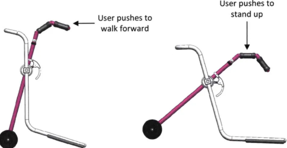
Before we begin discussing the improvements that can be made to the design, it is important to understand the original design itself. The walker, which has been given the name iXa Walker by the team, relies on a unique shape and a pivoting joint to achieve maximum effectiveness in both the upright and kneeling positions. The standing and the kneeling positions can be seen respectively in the figure below.
User pushes to User pushes to stand up
walk forward
Figure 2.1: Alpha prototype in standing and kneeling positions.
The front legs which are shown above in purple are equipped with a set of wheels on the bottom to make moving the walker around easier. The front leg is cut in half at the joint and welded into place. The top of the front legs have a unique design to accommodate both positions of the walker. The handles at the very end of the leg are slanted slightly downward and are meant to be used when pushing the walker around in the upright position. The handles are slanted downward in order to encourage the user to push the walker rather than lift it which leaves the walker more susceptible to tipping because the rear legs are lifted off of the ground. The secondary set of handles which are located directly in front of the other set of handles are for use while the walker is in the kneeling position. When the walker is in the down position these handles are roughly parallel to the ground and slightly further forward which promotes the force on the walker to be closer to the center of the walker which makes the walker less likely to tip out from under the user as they try to get up.
The rear legs which are shown in the figure above as silver is where the real innovation of the walker shows. Much different from conventional walkers, the rear legs of the iXa Walker have a large bend in them below the joint. This bend allows the transition from upright to kneeling positions possible. When the walker is in the upright position the very tips of the rear legs are the only points that contact the ground. Because of the wheels on the front legs of the walker allow the walker to be easily pushed, the minimal contact of the rear legs in the upright or walking position is ideal for reducing sliding friction between the back legs and the ground. In the kneeling or down position, the bottom half of the bend runs parallel to the ground in order to allow the user to slide the walker as far as possible under the chair, couch, or other sitting surface they are seated on in order to be more centered in the walker as well as provide support to the user as they are getting up. Both back legs run continuously through the rotating arm of the joint up into the crossbar of the walker. This allows the entire rear leg assembly to be built out of one piece. The crossbar running across the front of the walker is a unique feature of the walker that provides three distinct advantages to the walker. The first and
primary function is providing structural stability to the walker and ensuring that the rear legs remain aligned and can be raised and lowered at the same rate. The second purpose of the crossbar is providing visual stability for the user. By having a piece that runs across the front of the user will feel less like they could fall forward through the walker. The final benefit and the most innovative part of the crossbar is that because it is coupled with the rear legs, when the walker is adjusted to the kneeling position the rear legs move backward so the crossbar moves forward. This movement forward ensures that as the user gets up the crossbar will not be in a
position to hinder their ascent.
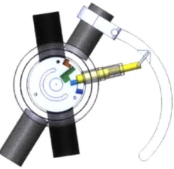
The final point of interest of the original design was the joint itself which can be seen in the figure below.
Figure 2.2: Cross section of radial pin locking joint of alpha prototype.
The joint used a radial pin actuated by pulling forward each of the handles on the front of the joint. Because of the geometry of the joint the front and rear legs were forced to be side by side rather than inline. When the pin was pulled out of the green hole in the up position the front and rear sections of the walker were free to rotate in relation to one and other until the pin reached the blue hole for the kneeling setting and locked into place.
3. Joint Redesign
The focus of this paper is to reexamine the joint as it fits into the overall design of the walker. Rather than addressing the specific analysis questions of how much stress is being applied to the pin holding the joint in place, the focus will be to examine certain features of the joint and how they can be modified to adapt the further research of my fellow iXa Walker teammates have done. The specific areas of this discussion include a comparison of using an axial pin versus a radial pin design, the alignment of the legs in relation to one and other, and the means by which the joint is integrated into the frame
Radial Pin vs. Axial Pin
The question of whether the joint should incorporate a radial or axial mounted pin is dependent upon the ease of incorporation into the overall design of the joint. Each orientation has its advantages and disadvantages and each should be carefully considered before reaching a decision.
The primary difference between the designs is the way in which the handle that releases the joint pin must be actuated. The radial design uses a handle that requires the user to pull in the same direction as the action that occurs after the handle is pulled. As the user pulls the joint handle toward them the handles of the walker which they use to get up fall toward them as well. In an axial design, because the pin would be coming out of the side of the joint, depending on the orientation of the pin, the user would have to pull outward or inward. This motion is perpendicular to the direction of the lift handles as they fall toward the user which tends to be less intuitive. However, there is a very important counterpoint to that thought. Because the user is pulling the handle toward them and is required to pull both handles at the same time, if the user cannot use their thumb or some other means to keep the rest of the walker stationary, the low coefficient of friction of the wheels on the ground will simply cause the walker to roll toward the user rather than releasing the lift handles into the kneeling position. Conversely, because the inward or outward forces of the axial pin cancel each other out and are perpendicular to the rolling of the wheels, the walker should not move while the user transitions the walker from the walking to kneeling positions.
Side by Side vs. Inline Leg Alignment
Alignment of the front and rear legs is an important design decision and both options require some tradeoffs in order to receive the benefits they offer to the design.
The primary difference between the two designs is the manner in which they limit the design of the walker. The side by side design requires much more width than the inline design. Because the overall tube diameter of the frame has been increased from 1" to 1.5" to eliminate some of the deflection of the frame this also increases the overall width of the walker by 1" on each side of the of the frame. This may not seem like a large difference, however it makes remaining within the design specifications of the team very difficult. The average width of an inside doorframe is approximately 28" and to ensure the user can easily navigate through the maximum outer to outer distance of the walker can only be 26". Two 1.5" pipes on either side of the user as well as added thickness from the joint causes the total thickness of the two joints to approach 8". This only leaves 18" for the interior width for the user which is below the typical 19-20" inner width of standard walkers. Because the total width of the tubes account for 6" of the 8" , there is little that can be done to reduce the total width of the joints and the
user must either deal with a narrow walker interior or a walker that is wider than most and may face difficulties when negotiating through narrow doorways. An exploded view of a same side by side setup can be seen in the figure below.
Figure 3.1: Exploded view of sample side by side joint setup.
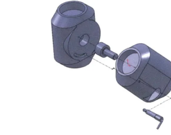
While this may make the side by side option seem like the obvious option to shy away from, the inline design faces a similar number of challenges. The increase in the radius of the frame tubing also affects the possibility of using an inline joint as well. The current diameter of the joint is 3", however because of the increase in frame diameter the diameter of the joint would have to be increased to just over 5" at the very minimum. While it decreases the thickness of the joint to roughly 1.5"-2" on each side, it dramatically increases the amount of material needed to make each joint properly. Aside from the material constraints, a joint that large may look bulky and unappealing to a potential user. This increase in joint diameter is conditional upon the use of the original walker geometry. The geometry may be able to be altered slightly in order to decrease the new joint diameter, but an increase in the diameter of the joint of some magnitude is inevitable. A simplistic sketch of how the two halves of an inline joint might fit together can be seen in the figure below.
Figure 3.2: Simplistic exploded view of an inline joint design.
The four tabs, two on each half, represent the spots at which the legs would be fastened. Each of the cylinders is only 0.80" thick while the tabs span the total 1.60" width of the joint allowing enough room for the 1.5" tubing to be fastened to each tab by the appropriate means.
Joint- Frame Integration
Another one of the crucial decisions in the redesign is how the joint is integrated into the design. The first variable to consider is whether the tubes of the frame run through the joint or are cut and welded on either side of the joint. By creating a design that allows the tubes to run through the joint you allow the rear leg/front cross bar piece to be able to be bent from one long solid piece of tubing. This ensures that the structure of the frame will be stronger as there are no breaks in the tubing at the joint. The drawbacks of having solid leg tubing are that first, the bending becomes a much more difficult task as keeping the bending aligned with the
proper plane for 6 different bends is necessary with such precise geometry. If the pieces of the leg were cut on either side of the joint and fastened into place the bottom and top pieces of each leg could be bent separately ensuring less error on each piece, however it also leads to alignment concerns when fastening each of these pieces to the joint because then 8 pieces must be properly aligned in each walker for the walker to stand without wobbling. Cutting the frame on either side of the joint adds an extra stress concentration to the two sections on each joint that will be taking the load while the user is getting up which is another potential failure
mode for the walker.
The other question in joint frame integration is the means in which the two are fastened together. Bolting and riveting are cheap methods that ensure proper alignment for the complex geometry. However, because this walker is under fairly large loading while the user is standing holes for alignment bolts or rivets inevitably have a tolerance and that slop can be compounded four times for each joint adding another potentially significant source of deflection that the user feels that was not initially accounted for. Welding is not a completely safe option either. While the strength and rigidity of the connection with a weld is stronger, you run the risk of deformations in the welding surface because of the extreme heat. If a portion of the joint slightly deforms during the welding process the geometry of the entire walker could be slightly askew.
Putting it All Together
After discussing each of the following aspects of the new joint design it was determined that overall width was the most important factor. By keeping the overall joint width similar to the width of the tubing in the frame it allows the walker to remain at an overall width comparable to standard walkers so there are no issues when trying to navigate through tight spaces while also ensuring that the inner width is large enough that the user can stand comfortably inside
while walking and getting up. Once front and rear leg alignment was chosen as the driving factor the other two factors were chosen through feasibility. The easiest way to minimize the width of the joint was to create two rotating pieces that overlapped. Because in this design the two pieces would have to rotate side by side rather than concentrically while ensuring a wide enough surface to properly mount the frame tubing an axial locking pin was chosen because a radial locking pin would not be able to properly constrain the two halves. The side by side rotating discs also did not allow for solid tubes to run through the joint so a cut and weld design was chosen instead.
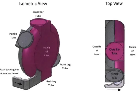
Keeping these three factors in mind the new joint was designed to improve the overall joint-frame integration in the beta prototype. An isometric and top view of the joint can be seen in the figure below.
Isometric View Top View
Cross Bar Tube Handle Tube Outside Inside of of Joint Joint Front Leg Axial Locking Pin Tube
Actuation Lever
Back Leg Tube
Figure 3.3: Isometric and top views of the new joint design.
The exterior portion of the joint has three major components, the inner and outer halves of the joint that connect to the rear and front legs respectively and the lever which connects to the pin that locks the joint in place. Both the inner and outer halves have two tabs that span the full width of the joint overlapping the opposite section. The tabs are large enough so that a shallow circle with a radius of 1.5" can be incorporated on each tab so that the tubes of the legs can be
easily welded to the joint in the precise location. The tabs on each side are located 180 degrees from each other so that the geometry stays as if each tube ran directly through the center of the joint. Each of the halves is filleted to give the joint a more streamlined shape and to
eliminate any sharp edge that may pose a threat to the user.
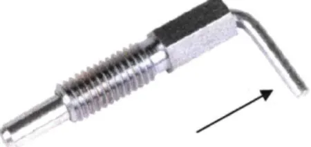
The other portion of the exterior is the lever which is located on the inner half of the joint. The lever will be coupled in with a spring plunger similar to the one shown in the figure below.
Figure 3.4: Axial L-shaped spring plunger used in new joint design.
The pin and the front face of the lever move in parallel to one and other by pushing inward on the lever and will be connected by press fitting the lever onto the L shaped portion of the plunger. This was done so that the user could easily grab the two joint handles with two fingers each, pull the walker toward them so that it is in the proper location for when the walker falls to the kneeling position and then push both of the levers inward as shown by the arrows on Figure 3.3 to unlock the walker from the standing position. The lift handles will then rotate toward the user while the cross bar rotates away until the hard stop inside the joint stops the walker in the kneeling position. The user then gets up and lifts the walker up causing it to rotate back into the standing position. The locking pin then clicks as it falls back into the hole signifying to the user that the walker is safely in the position for them to use as they walk around
4. New Joint Analysis
Deflection
In order to ensure that the user feels comfortable using the walker to stand from a seated position it was determined that a lift handle deflection of less than 2 cm would be sufficient. This deflection is the maximum allowable deflection of all of the parts including the bending of the frame and the bending in the interior of the joint. When these two calculations were done it was assumed that the deflection of the exterior of the joint would be negligible. The manner in which the new joint is constructed allows this to be true. The two pieces of the joint are locked in place by a pin. The deflection of that lift handle because of that pin is covered in the analysis of the interior of the joint. The joint is welded to the pieces of the frame causing the frame to treat the joint as a rigid piece of the frame. The bending of the tubes caused by them being cantilevered in the joint by the weld is similar to what the bending of frame would be if there was simply solid tubing instead of a joint. This means that the bending of these weld sites is covered by the bending analysis and the original assumption that the exterior of the joint will
contribute a negligible amount of deflection to the total deflection of the walker lift handle stands. This means as long as the other two segments meet their specifications, the deflection will be small enough so that the user does not notice and feels comfortable using the product.
Material Selection
Because the joint requires the frame tubes of both the front and the rear legs to be cut and welded to the joint, the material selection process for the joint is fairly limited. In order to make a clean weld the joints must be made of a similar type of aluminum. Because the joint was increased in diameter in order to accommodate the current geometry while allowing the front and rear legs to be in line, there is a significant amount of material added to the total joint. If the joint was made out of solid 6061 aluminum, each of the hemispheres of the joint would weigh 1.49 lbs. With two of these pieces per joint and two joints per walker, the total joint weight of the walker would be on the order of 6 lbs. While this does not seem like much, total walker weight becomes an issue for users who are typically elderly or suffer muscle weakness which could cause problems if the walker had to be continually lifted or pushed. A large amount of extra material is also unappealing from a business perspective as it only increases manufacturing costs.
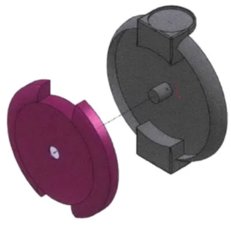
In order to minimize the weight of each of the pieces of the joint, the aluminum hemisphere was shelled out to maintain all of the necessary features that need to be aluminum while eliminating excess material. Because this piece is not aesthetically pleasing, the piece of aluminum was then shelled out as well and switched to be made out of a plastic material. This piece can then be injection molded and press fit into the aluminum shell so that the joint maintains a similar look. The figure below shows an exploded view of the aluminum piece in grey and the plastic press fit insert in pink.
Figure 4.1: Exploded view of weight optimized joint.
This change causes the aluminum piece to decrease from 1.49 lbs to 0.61 lbs and with the plastic insert the total new weight of the joint piece is 0.71lbs, less than half of the original weight. With this minor improvement the total joint weight of the walker will be approximately 3 lbs instead of 6 lbs while still performing with the same functionality of a solid aluminum joint.
Design For Manufacturing and Assembly (DMFA)
In order for the second prototype to be successfully patented the design must consider some constraints that would allow it to be successfully manufactured.
Because the joints are mirror images of one and other, the four aluminum pieces that compose the majority of the joint are all unique. Depending on cost and volume the options include making one mold to cast a generic piece which is then machined into the four unique parts or creating a separate mold for each of the four parts to be cast individually.
The other pieces of the joint are made from plastic and can easily be injection molded. The outside plastic insert is the same for both so that reduces the number of molds by one, however separate molds will have to be created for the inner left and inner right inserts as well as the left and right handles.
Cutting the tubing ensures the accuracy of the bending of the rear leg because the bottom portion of the leg which is the most crucial to the geometry are now two pieces with one bend each rather than one connected piece that includes those two bends and the four bends of the crossbar where the error can be compounded if each bend is slightly out of place or at the wrong location. As long as the two rear legs are properly aligned before being welded, the
likelihood of there being error in the geometry is significantly less.
The welding alignment is crucial for the proper functionality of the walker. Because each of the four pieces has a unique feature such as a bend or hole, a simple jig could be created to assure the alignment of the pieces and then they could be tacked into place.
The walker can be assembled in a way that keeps the left and right legs separate until near the end of the process. The first step would be to weld both pieces of the front leg to the outer joint and the bottom portion of the rear leg to the inner half of the joint making sure they are properly aligned. The outer and inner half of the joints could then be assembled causing each leg to be three quarters complete. The left and right pieces could then be put together by welding the front leg crossbar between the two front legs and then the top crossbar onto the joint. At this point the welding is complete and the frame can be powder coated to the desired color before the handles, wheels, levers, joint cap inserts, and any other accessories are added completing the assembly process.
Further Research/Design
While this design has taken into consideration the three biggest points of emphasis in improving the overall joint design, it is not to say that all of the integration questions have been answered. Several of the areas that have not been covered in this research or the concurrent research of my colleagues working on the logistics of the frame or the analysis of the interior of the joint includes optimizing the geometry of the frame, position transition optimization, and user research and testing.
With such a unique design the geometry is the most crucial and delicate portion of the design. Now that the optimal tubing diameter has been found it can be included in the optimization of the geometry. Increasing the tubing size, while keeping the geometry constant, proved to be problematic in creating an inline joint of a similar size to the alpha prototype. With geometry optimization the diameter of the joint could potentially be significantly reduced to both improve the aesthetics and reduce material costs.
Another aspect that can be improved upon with the new research that has been done is improving the transition between the standing and the kneeling positions. Currently there is nothing controlling speed of rotation of the joint as it falls into the kneeling position which could prove to be a problem if the falling pushing handles hit the users immediately after they actuate the joint handle. The other option is to include some sort of return mechanism that causes the walker to return to the standing position after the user has lifted themselves to the standing position. This would prove more consistent than relying on gravity to force the legs to lock back in the standing position causing the walker to be safer.
The final, and probably most important, area of research is further user research and testing. All of these improvements may appear to be beneficial, but if the average user does not like them or cannot use them then the walker will not be purchased. Things such as increased tubing, new axial joint actuation, increased joint size, overall stability, and overall aesthetics play a crucial role in the successful design of a new walker, but only if they are accepted by the people that will be using the actual walker.
5. Conclusion
In focusing on the exterior of the joint three particular weaknesses of the original alpha prototype of iXa Walker were identified. These were then each compared and contrasted to a potential design alternative in order to combine the three aspects in a way that optimized the exterior of the joint. The new joint design includes inline front and rear legs, an axial joint
locking pin, and integrates the joint into the frame through cutting and welding the tubes on either side of the joint. These features best combined to meet all of the original goals of the iXa Walker while improving upon some problems encountered in the alpha prototype phases. By combining this research with the research being done by my colleagues on the frame bending analysis and the locking pin bending analysis a successful beta prototype could be created in the process of creating a unique specialty walker that aids the user in rising from a seated position in a safe and efficient manner.
References
1. iXa Walker Website.
<http://www.ixawalker.com/>
2. "2.009 product Engineering Process." 2008. Massachusetts Institute of Technology. 16 May 2010. <http://web.mit.edu/2.009/www/index.html>.
3. "L-Handle Retractable Non-Locking Spring Plunger Image." 2006. Springplungers.com. 16 May 2010.